2007 ISUZU KB P190 weight
[x] Cancel search: weightPage 2805 of 6020
Engine Mechanical – V6 Page 6A1–28
Page 6A1–28
Pipe Joint Compound
• Pipe joint compound is a pliable sealer that does not comp letely harden. This type of sealer is used where two non-
rigid parts (such as pressed steel and ma chined surfaces) are assembled together.
• Do not use pipe joint compound in areas where extreme temperatures are expected. These areas include the
exhaust manifold, head gasket, or other surfaces where gasket eliminator is specified.
• Follow all safety recommendations and di rections that are on the container.
• To remove the sealant or the gasket mate rial, refer to Replacing Engine Gaskets.
• Apply the pipe joint compound to a clean surface. Use a bead size or quantity as specified in the procedure. Run
the bead to the inside of any bolt holes. Do not allow the s ealer to enter any blind threaded holes as it may prevent
the bolt from clamping correctly or caus e component damage when the bolt is tightened.
• Apply a continuous bead of pipe joint compound to one seali ng surface. Sealing surfaces to be resealed must be
clean and dry.
• Tighten the bolts to the correct torque specification. Do not over-tighten.
Separating Parts
CAUTION
Many internal engine components will
develop specific wear patterns on their
friction surfaces. When disassembling the
engine, internal components must be
separated, marked and organised in a way to
ensure reinstallation in their original location
and position.
Separate, mark, or organise the following components:
• Piston and the piston pin.
• Piston to the specific cylinder bore.
• Piston rings to the specific piston.
• Connecting rod to the crankshaft journal.
• Connecting rod to the bearing cap.
• Crankshaft main and connecting rod bearings.
• Camshaft and rocker arms.
• Rocker arms and stationary hydraulic lash adjusters to cylinder head location.
• Valve to the valve guide.
• Valve spring and shim to the cylinder head location.
• Engine block main bearing cap location and direction.
• Oil pump drive and driven gears.
Tools and Equipment
Special tools are listed and illustrated throughout this Section with a complete listing at the end, refer to 7 Special Tools.
These tools (or their equivalents) are specially designed to quickly and safely accomplish the operations for which they
are intended. The use of these special tools will also minimise possible damage to engine components. Some precision
measuring tools are required for inspec tion of certain critical components. A commercially available torque wrench and
torque angle wrench, Tool No. EN-7115 are required for the correct tightening of various fasteners.
To correctly service the engine assembly, the following items should be readily available:
• Approved eye protection and safety gloves.
• A clean, well-lit, work area.
• A suitable parts cleaning tank.
• A compressed air supply.
• Trays or storage containers to keep parts and fasteners organised.
• An adequate set of hand tools.
• Approved engine repair stand.
• An approved engine lifting device that will adequatel y support the weight of the components.
BACK TO CHAPTER INDEX
TO MODEL INDEX
ISUZU KB P190 2007
Page 3013 of 6020
Engine Mechanical – V6 Page 6A1–236
Page 6A1–236
3.24 Engine Mounts and Brackets
Remove
1 Remove the exhaust manifold assembly from the side of the engine where the engine mount is to be removed,
refer to 3.11 Exhaust Manifold Assembly .
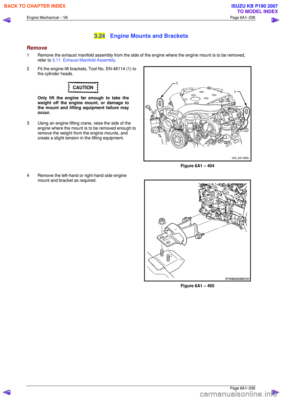
2 Fit the engine lift brackets, Tool No. EN-46114 (1) to the cylinder heads.
CAUTION
Only lift the engine far enough to take the
weight off the engine mount, or damage to
the mount and lifting equipment failure may
occur.
3 Using an engine lifting crane, raise the side of the
engine where the mount is to be removed enough to
remove the weight fr om the engine mounts, and
create a slight tension in the lifting equipment.
Figure 6A1 – 404
4 Remove the left-hand or right-hand side engine mount and bracket as required.
Figure 6A1 – 405
BACK TO CHAPTER INDEX
TO MODEL INDEX
ISUZU KB P190 2007
Page 3014 of 6020
Engine Mechanical – V6 Page 6A1–237
Page 6A1–237
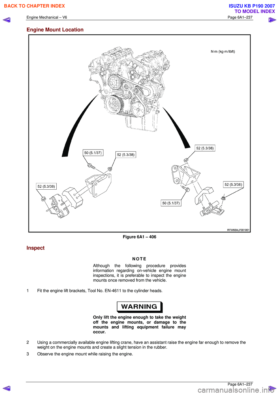
Engine Mount Location
Figure 6A1 – 406
Inspect
NOTE
Although the following procedure provides
information regarding on-vehicle engine mount
inspections, it is prefer able to inspect the engine
mounts once removed from the vehicle.
1 Fit the engine lift brackets, Tool No. EN-4611 to the cylinder heads.
Only lift the engine enough to take the weight
off the engine mounts, or damage to the
mounts and lifting equipment failure may
occur.
2 Using a commercially available engine lifting crane, hav e an assistant raise the engine far enough to remove the
weight on the engine mounts and create a slight tension in the rubber.
3 Observe the engine mount while raising the engine.
BACK TO CHAPTER INDEX
TO MODEL INDEX
ISUZU KB P190 2007
Page 3023 of 6020
Engine Mechanical – V6 Page 6A1–246
Page 6A1–246
Figure 6A1 – 423
Figure 6A1 – 424
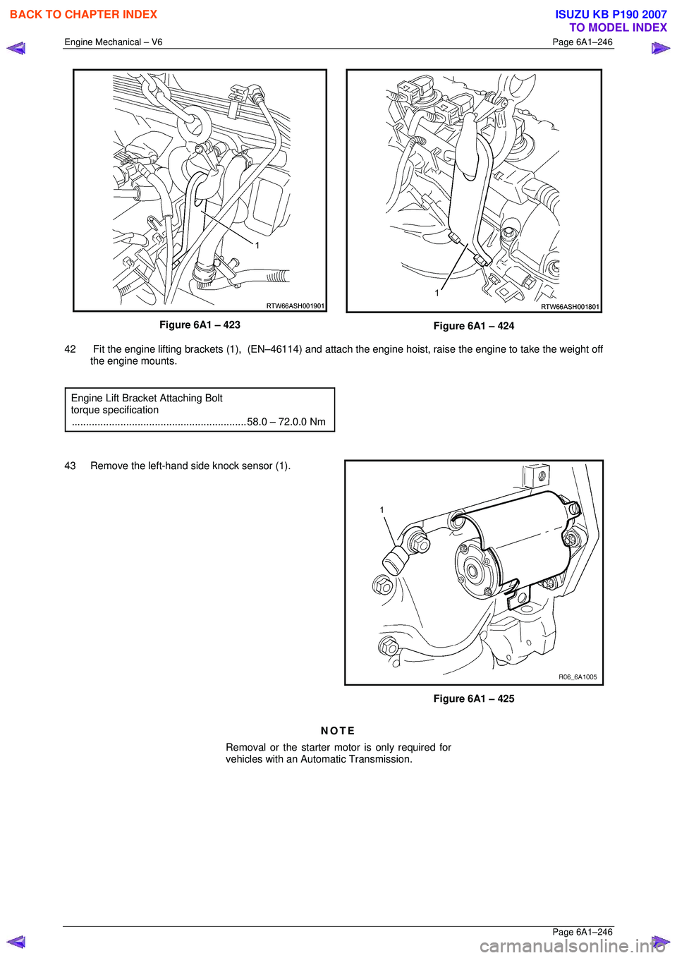
42 Fit the engine lifting brackets (1), (EN–46114) and attach the engine hoist, raise the engine to take the weight off the engine mounts.
Engine Lift Bracket Attaching Bolt
torque specification
............................................................. 58.0 – 72.0.0 Nm
43 Remove the left-hand side knock sensor (1).
Figure 6A1 – 425
NOTE
Removal or the starter motor is only required for
vehicles with an Automatic Transmission.
BACK TO CHAPTER INDEX
TO MODEL INDEX
ISUZU KB P190 2007
Page 3042 of 6020
Engine Mechanical – V6 Page 6A1–265
Page 6A1–265
4.5 Pistons, Pins, Rings, Connecting Rods
and Big-end Bearings
Remove
1 Remove the engine assembly, refer to 4.1 Engine .
2 Remove both cylinder head assemblies, refer to 3.22 Cylinder Head Assembly.
3 Remove the oil pan assembly, refer to 4.2 Oil Pan and Oil Pump Suction Pipe Assembly .
4 Mark the top of the piston being remo ved to identify its specific bore.
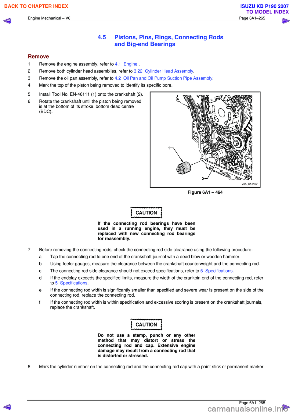
5 Install Tool No. EN-46111 (1) onto the crankshaft (2).
6 Rotate the crankshaft until the piston being removed is at the bottom of its stroke; bottom dead centre
(BDC).
Figure 6A1 – 464
CAUTION
If the connecting rod bearings have been
used in a running engine, they must be
replaced with new connecting rod bearings
for reassembly.
7 Before removing the connecting rods, check the connec ting rod side clearance using the following procedure:
a Tap the connecting rod to one end of the cranks haft journal with a dead blow or wooden hammer.
b Using feeler gauges, measure the clearance between the crankshaft counterweight and the connecting rod.
c The connecting rod side clearance should not exceed specifications, refer to 5 Specifications.
d If the endplay exceeds the specified limits, measure the width of the crankpin end of the connecting rod, refer
to 5 Specifications .
e If the connecting rod width is significantly smaller than specified and severe wear is present on the side of the
connecting rod, replac e the connecting rod.
f If the connecting rod width is within specification and excessive scoring is present on the crankshaft journals,
replace the crankshaft.
CAUTION
Do not use a stamp, punch or any other
method that may distort or stress the
connecting rod and cap. Extensive engine
damage may result from a connecting rod that
is distorted or stressed.
8 Mark the cylinder number on the connec ting rod and the connecting rod cap with a paint stick or permanent marker.
BACK TO CHAPTER INDEX
TO MODEL INDEX
ISUZU KB P190 2007
Page 3061 of 6020
Engine Mechanical – V6 Page 6A1–284
Page 6A1–284
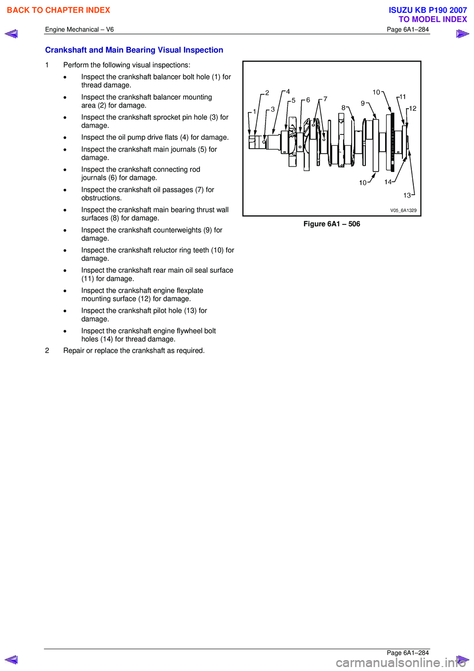
Crankshaft and Main Bearing Visual Inspection
1 Perform the following visual inspections:
• Inspect the crankshaft balancer bolt hole (1) for
thread damage.
• Inspect the crankshaft balancer mounting
area (2) for damage.
• Inspect the crankshaft sprocket pin hole (3) for
damage.
• Inspect the oil pump drive flats (4) for damage.
• Inspect the crankshaft main journals (5) for
damage.
• Inspect the crankshaft connecting rod
journals (6) for damage.
• Inspect the crankshaft oil passages (7) for
obstructions.
• Inspect the crankshaft main bearing thrust wall
surfaces (8) for damage.
• Inspect the crankshaft counterweights (9) for
damage.
• Inspect the crankshaft reluctor ring teeth (10) for
damage.
• Inspect the crankshaft rear main oil seal surface
(11) for damage.
• Inspect the crankshaft engine flexplate
mounting surface (12) for damage.
• Inspect the crankshaft pilot hole (13) for
damage.
• Inspect the crankshaft engine flywheel bolt
holes (14) for thread damage.
2 Repair or replace the crankshaft as required.
Figure 6A1 – 506
BACK TO CHAPTER INDEX
TO MODEL INDEX
ISUZU KB P190 2007
Page 3611 of 6020
Starting System – V6 Page 6D1-2–3
1 General Information
All HFV6 engines are fitted with a Mitsubishi starter motor. This consists of a solenoid switch on a DC motor. The motor
has permanent magnet excitation, which has the advantage of low weight a with high output torque and is visually
identifiable by the absence of pole-shoe retaining screws.
The starter motor does not have field coil windings or pole shoes. These parts have been replaced by six permanent
magnets that are held in the pole housing by clips. The positive brushes are now part of the brush plate assembly.
The solenoid switch is the only component of the starter motor assembly that is serviced separately. If any other parts
require replacement, the starter motor must be replaced.
1.1 WARNING, CAUTION and NOTES
This Section contains various W ARNINGS, CAUTIONS and NOTE statements that you must observe carefully to reduce
the risk of death or injury during service, repair procedures or vehicle operation. Incorrect service or repair procedures
may damage the vehicle or cause operational faults. W ARNINGS, CAUTION and NOTE statements are not exhaustive.
HOLDEN LTD can not possibly warn of all the potentially hazardous consequences of failure to follow these instructions.
Definition of WARNING, CAUTION and NOTE Statements
Diagnosis and repair procedures in this Section contain both general and specific W ARNING, CAUTION and NOTE
statements. HOLDEN LTD is dedicated to the presentation of service information that helps the technician to diagnose
and repair the systems necessary for proper operation of the vehicle. Certain procedures may present a hazard to the
technician if they are not followed in the recommended manner. W ARNING, CAUTION and NOTE statements are
designed to help prevent these hazards from occurring, but not all hazards can be foreseen.
WARNING defined
A W ARNING statement immediately precedes an operating procedure or maintenance practice which, if not correctly
followed, could result in death or injury. A W ARNING statement alerts you to take necessary action or not to take a
prohibited action. If a W ARNING statement is ignored, the following consequences may occur:
• Death or injury to the technician or other personnel working on the vehicle,
• Death or injury to other people in or near the workplace area, and / or
• Death or injury to the driver / or passenger(s) of the vehicle or other people, if the vehicle has been improperly
repaired.
CAUTION defined
A CAUTION statement immediately precedes an operating procedure or maintenance practice which, if not correctly
followed, could result in damage to or destruction of equipment, or corruption of data. If a CAUTION statement is ignored,
the following consequences may occur:
• Damage to the vehicle,
• Unnecessary vehicle repairs or component replacement,
• Faulty operation or performance of any system or component being repaired,
• Damage to any system or components which depend on the proper operation of the system or component being
repaired,
• Faulty operation or performance of any systems or components which depend on the proper operation or
performance of the system or component under repair,
• Damage to fasteners, basic tools or special tools and / or
• Leakage of coolant, lubricant or other vital fluids.
NOTE defined
A NOTE statement immediately precedes or follows an operating procedure, maintenance practice or condition that
requires highlighting. A NOTE statement also emphasises necessary characteristics of a diagnostic or repair procedure.
A NOTE statement is designed to:
BACK TO CHAPTER INDEX
TO MODEL INDEX
ISUZU KB P190 2007
Page 4567 of 6020
MSG MODEL 7B-3
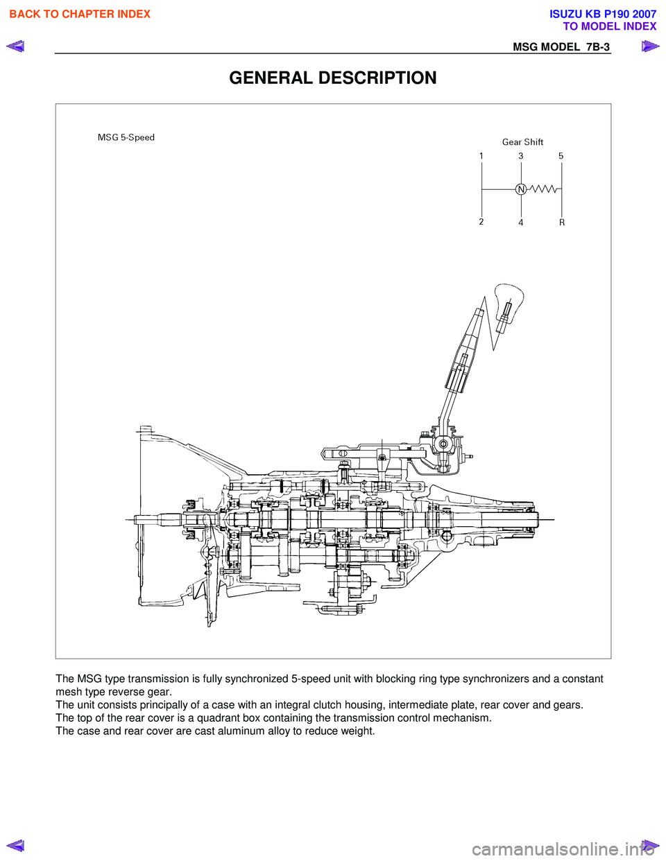
GENERAL DESCRIPTION
The MSG type transmission is fully synchronized 5-speed unit with blocking ring type synchronizers and a constant
mesh type reverse gear.
The unit consists principally of a case with an integral clutch housing, intermediate plate, rear cover and gears.
The top of the rear cover is a quadrant box containing the transmission control mechanism.
The case and rear cover are cast aluminum alloy to reduce weight.
BACK TO CHAPTER INDEX
TO MODEL INDEX
ISUZU KB P190 2007