2007 ISUZU KB P190 weight
[x] Cancel search: weightPage 2117 of 6020
ENGINE COOLING 6B-13
Installation
1. Install radiator assembly, taking care not to damage theradiator core.
2. Install the radiator assembly.
3. Connect reserve tank hose.
4. Connect radiator inlet hose and outlet hose.
5. Pour engine coolant up to filler neck of radiator, and up to MAX mark of reserve tank.
Important operation (in case of 100% engine coolant change) procedure for filling with engine coolant.
• Remove radiator cap.
• Fill with engine coolant to the radiator filler neck.
• Fill with EC to the "MAX" line on the reservoir tank.
• Start the engine with the radiator cap removed and bring to
operating temperature by running engine at 2,500 - 3,000
rpm for 30 minutes.
• By engine coolant temperature gauge reading make sure
that the thermostat is open.
• If air bubbles come up to the radiator filler neck, replenish
with engine coolant. Repeat until the EC level does not drop
any further. Install the radiator cap and stop the engine.
• Replenish engine coolant to the "MAX" line on the reservoi
r
tank and leave as it is until the engine gets cool.
•
After the engine gets cool, start the engine and make sure
there is no water running noise heard from the heater core
while the engine runs at 3000 rpm.
• Should water running noise be heard, repeat the same
procedure from the beginning.
Main Data and Specifications
General Specifications
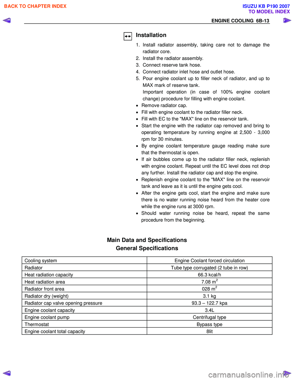
Cooling system Engine Coolant forced circulation
Radiator Tube type corrugated (2 tube in row)
Heat radiation capacity 66.3 kcal/h
Heat radiation area 7.08 m2
Radiator front area 028 m2
Radiator dry (weight) 3.1 kg
Radiator cap valve opening pressure 93.3 – 122.7 kpa
Engine coolant capacity 3.4L
Engine coolant pump Centrifugal type
Thermostat Bypass type
Engine coolant total capacity 8lit
BACK TO CHAPTER INDEX
TO MODEL INDEX
ISUZU KB P190 2007
Page 2222 of 6020
6E–52 ENGINE DRIVEABILITY AND EMISSIONS
GENERAL DESCRIPTION FOR FUEL
METERING
The fuel metering system starts with the fuel in the fuel
tank. An electric fuel pump, located in the fuel tank,
pumps fuel to the fuel rail through an in-line fuel filter.
The pump is designed to provide fuel at a pressure
above the pressure needed by the injectors.
A fuel pressure regulator in the fuel rail keeps fuel
available to the fuel injectors at a constant pressure.
A return line delivers unused fuel back to the fuel tank.
The basic function of the air/fuel metering system is to
control the air/fuel delivery to the engine. Fuel is
delivered to the engine by individual fuel injectors
mounted in the intake manifold.
The main control sensor is the heated oxygen sensor
located in the exhaust system. The heated oxygen
sensor reports to the ECM how much oxygen is in the
exhaust gas. The ECM changes the air/fuel ratio to the
engine by controlling the amount of time that fuel
injector is “On”.
The best mixture to minimize exhaust emissions is 14.7
parts of air to 1 part of gasoline by weight, which allows
the catalytic converter to operate most efficiently.
Because of the constant measuring and adjusting of the
air/fuel ratio, the fuel injection system is called a “closed
loop” system.
The ECM monitors signals from several sensors in
order to determine the fuel needs of the engine. Fuel is
delivered under one of several conditions called “mode”.
All modes are controlled by the ECM.
Battery Voltage Correction Mode
When battery voltage is low, the ECM will compensate
for the weak spark by increasing the following:
• The amount of fuel delivered.
• The idle RPM.
Clear Flood Mode
Clear a flooded engine by pushing the accelerator pedal
down all the way. The ECM then de-energizes the fuel
injectors. The ECM holds the fuel injectors de-energized
as long as the throttle remains above 75% and the
engine speed is below 800 RPM. If the throttle position
becomes less than 75%, the ECM again begins to pulse
the injectors ON and OFF, allowing fuel into the
cylinders.
Deceleration Fuel Cutoff (DFCO) Mode
The ECM reduces the amount of fuel injected when it
detects a decrease in the throttle position and the air
flow. When deceleration is very fast, the ECM may cut
off fuel completely. Until enable conditions meet the
engine revolution less 1000 rpm or manifold absolute
pressure less than 10 kPa.
Engine Speed/ Vehicle Speed/ Fuel Disable
Mode
The ECM monitors engine speed. It turns off the fuel
injectors when the engine speed increases above 6000
RPM. The fuel injectors are turned back on when
engine speed decreases below 3500 RPM.
Acceleration Mode
The ECM provides extra fuel when it detects a rapid
increase in the throttle position and the air flow.
Fuel Cutoff Mode
No fuel is delivered by the fuel injectors when the
ignition is OFF. This prevents engine run-on. In addition,
the ECM suspends fuel delivery if no reference pulses
are detected (engine not running) to prevent engine
flooding.
Starting Mode
When the ignition is first turned ON, the ECM energizes
the fuel pump relay for two seconds to allow the fuel
pump to build up pressure. The ECM then checks the
engine coolant temperature (ECT) sensor and the
throttle position sensor to determine the proper air/fuel
ratio for starting.
The ECM controls the amount of fuel delivered in the
starting mode by adjusting how long the fuel injectors
are energized by pulsing the injectors for very short
times.
Run Mode
The run mode has the following two conditions:
• Open loop
• Closed loop
When the engine is first started, the system is in “open
loop” operation. In “Open Loop,” the ECM ignores the
signal from the heated oxygen sensor (HO2S). It
calculates the air/fuel ratio based on inputs from the TP,
ECT, and MAP sensors.
The system remains in “Open Loop” until the following
conditions are met:
• The HO2S has a varying voltage output showing that it is hot enough to operate properly (this depends on
temperature).
• The ECT has reached a specified temperature.
• A specific amount of time has elapsed since starting the engine.
• Engine speed has been greater than a specified RPM since start-up.
The specific values for the above conditions vary with
different engines and are stored in the programmable
read only memory (PROM). When these conditions are
met, the system enters “closed loop” operation. In
“closed loop,” the ECM calculates the air/fuel ratio
(injector on-time) based on the signal from the HO2S.
This allows the air/fuel ratio to stay very close to 14.7:1.
BACK TO CHAPTER INDEX
TO MODEL INDEX
ISUZU KB P190 2007
Page 2506 of 6020
Engine Mechanical – V6 Page 6A1–27
• A clean, well-lit, work area.
• A suitable parts cleaning tank.
• A compressed air supply.
• Trays or storage containers to keep parts and fasteners organised.
• An adequate set of hand tools.
• Approved engine repair stand.
• An approved engine lifting device that will adequately support the weight of the components.
Fasteners
Fasteners are central to the reliable operation of an engine.
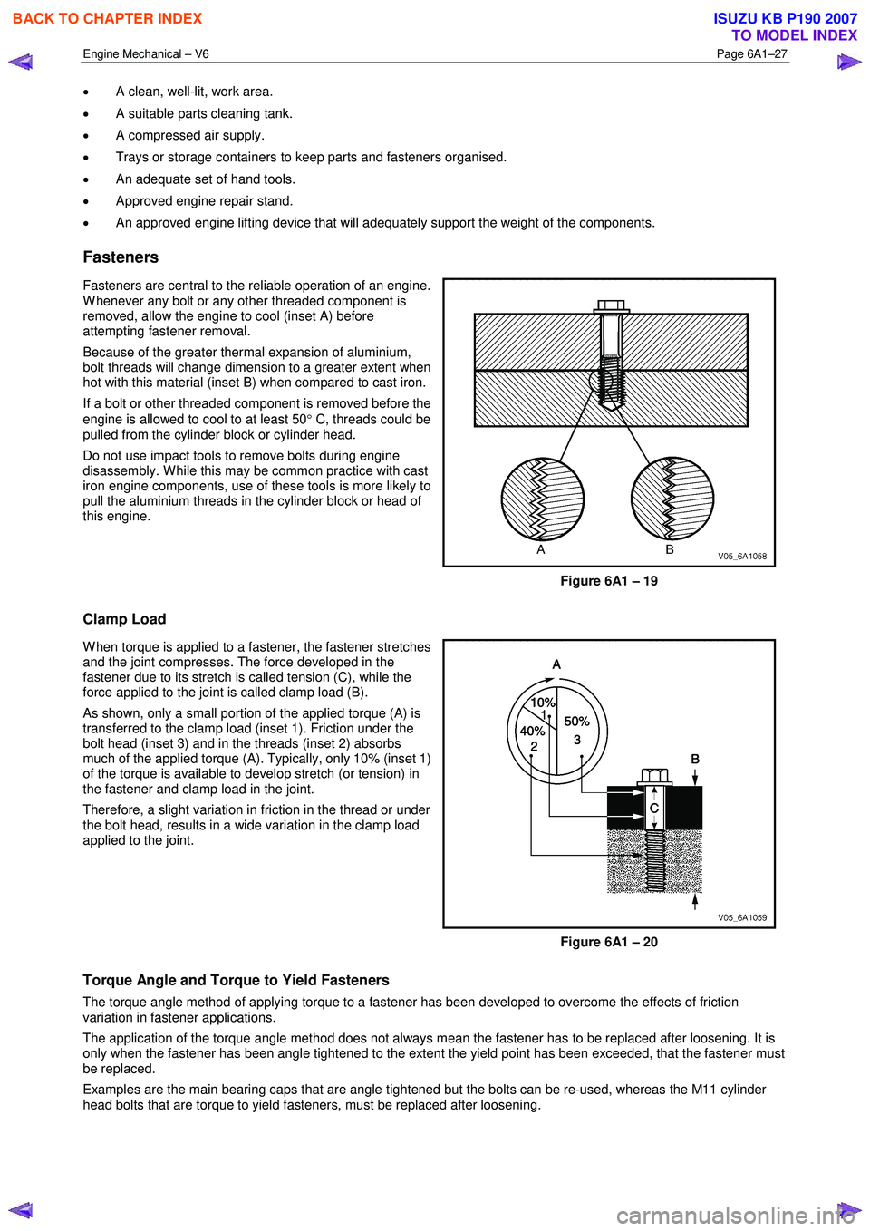
W henever any bolt or any other threaded component is
removed, allow the engine to cool (inset A) before
attempting fastener removal.
Because of the greater thermal expansion of aluminium,
bolt threads will change dimension to a greater extent when
hot with this material (inset B) when compared to cast iron.
If a bolt or other threaded component is removed before the
engine is allowed to cool to at least 50 ° C, threads could be
pulled from the cylinder block or cylinder head.
Do not use impact tools to remove bolts during engine
disassembly. W hile this may be common practice with cast
iron engine components, use of these tools is more likely to
pull the aluminium threads in the cylinder block or head of
this engine.
Figure 6A1 – 19
Clamp Load
W hen torque is applied to a fastener, the fastener stretches
and the joint compresses. The force developed in the
fastener due to its stretch is called tension (C), while the
force applied to the joint is called clamp load (B).
As shown, only a small portion of the applied torque (A) is
transferred to the clamp load (inset 1). Friction under the
bolt head (inset 3) and in the threads (inset 2) absorbs
much of the applied torque (A). Typically, only 10% (inset 1)
of the torque is available to develop stretch (or tension) in
the fastener and clamp load in the joint.
Therefore, a slight variation in friction in the thread or under
the bolt head, results in a wide variation in the clamp load
applied to the joint.
Figure 6A1 – 20
Torque Angle and Torque to Yield Fasteners
The torque angle method of applying torque to a fastener has been developed to overcome the effects of friction
variation in fastener applications.
The application of the torque angle method does not always mean the fastener has to be replaced after loosening. It is
only when the fastener has been angle tightened to the extent the yield point has been exceeded, that the fastener must
be replaced.
Examples are the main bearing caps that are angle tightened but the bolts can be re-used, whereas the M11 cylinder
head bolts that are torque to yield fasteners, must be replaced after loosening.
BACK TO CHAPTER INDEX
TO MODEL INDEX
ISUZU KB P190 2007
Page 2660 of 6020
Engine Mechanical – V6 Page 6A1–181
3.23 Engine Mounts and Brackets
Remove
1 Remove the exhaust manifold assembly from the side of the engine where the engine mount is to be removed,
refer to 3.11 Exhaust Manifold Assembly.
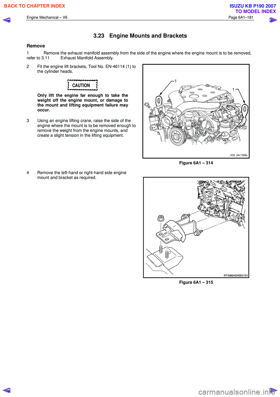
2 Fit the engine lift brackets, Tool No. EN-46114 (1) to the cylinder heads.
CAUTION
Only lift the engine far enough to take the
weight off the engine mount, or damage to
the mount and lifting equipment failure may
occur.
3 Using an engine lifting crane, raise the side of the engine where the mount is to be removed enough to
remove the weight from the engine mounts, and
create a slight tension in the lifting equipment.
Figure 6A1 – 314
4 Remove the left-hand or right-hand side engine mount and bracket as required.
Figure 6A1 – 315
BACK TO CHAPTER INDEX
TO MODEL INDEX
ISUZU KB P190 2007
Page 2661 of 6020
Engine Mechanical – V6 Page 6A1–182
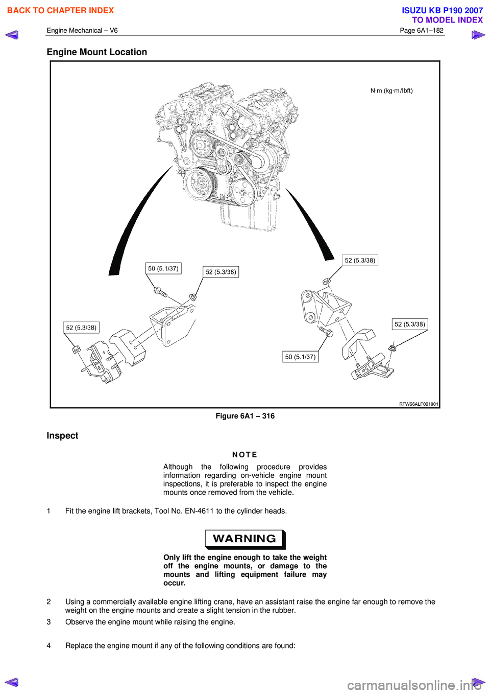
Engine Mount Location
Figure 6A1 – 316
Inspect
NOTE
Although the following procedure provides
information regarding on-vehicle engine mount
inspections, it is preferable to inspect the engine
mounts once removed from the vehicle.
1 Fit the engine lift brackets, Tool No. EN-4611 to the cylinder heads.
Only lift the engine enough to take the weight
off the engine mounts, or damage to the
mounts and lifting equipment failure may
occur.
2 Using a commercially available engine lifting crane, have an assistant raise the engine far enough to remove the weight on the engine mounts and create a slight tension in the rubber.
3 Observe the engine mount while raising the engine.
4 Replace the engine mount if any of the following conditions are found:
BACK TO CHAPTER INDEX
TO MODEL INDEX
ISUZU KB P190 2007
Page 2670 of 6020
Engine Mechanical – V6 Page 6A1–191
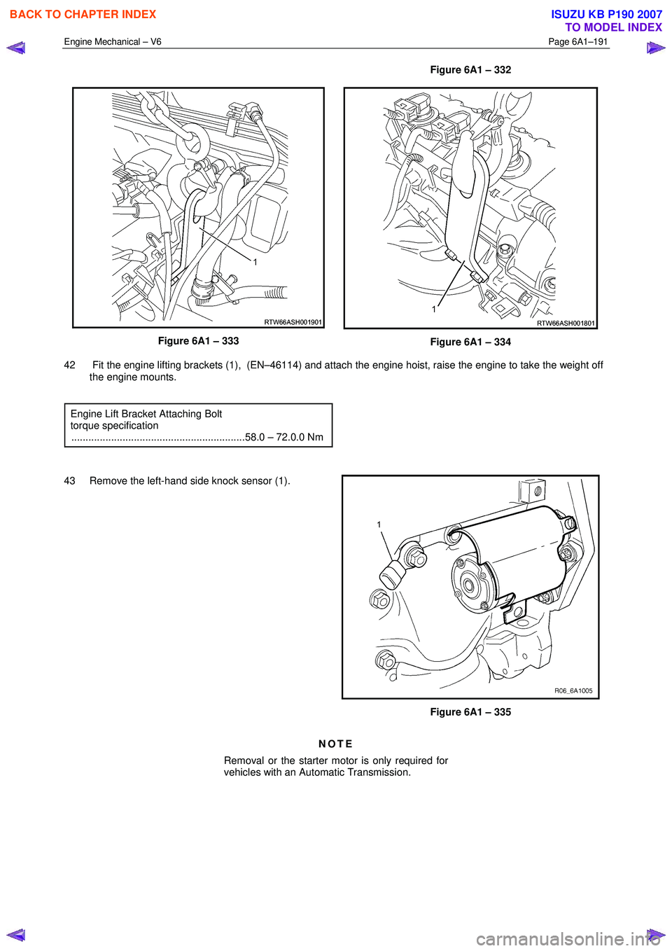
Figure 6A1 – 332
Figure 6A1 – 333 Figure 6A1 – 334
42 Fit the engine lifting brackets (1), (EN–46114) and attach the engine hoist, raise the engine to take the weight off the engine mounts.
Engine Lift Bracket Attaching Bolt
torque specification
.............................................................58.0 – 72.0.0 Nm
43 Remove the left-hand side knock sensor (1).
Figure 6A1 – 335
NOTE
Removal or the starter motor is only required for
vehicles with an Automatic Transmission.
BACK TO CHAPTER INDEX
TO MODEL INDEX
ISUZU KB P190 2007
Page 2687 of 6020
Engine Mechanical – V6 Page 6A1–208
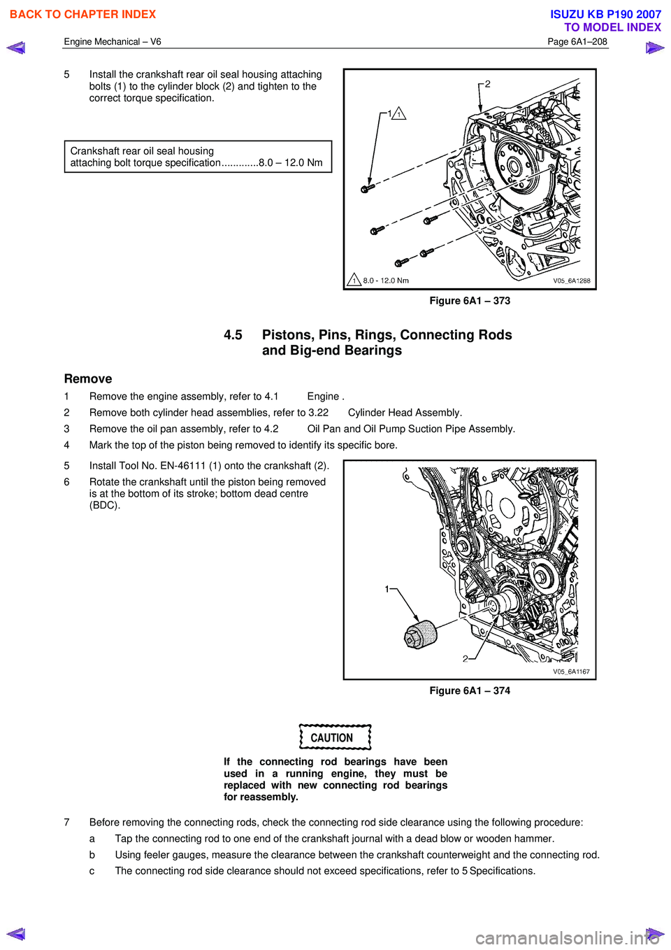
5 Install the crankshaft rear oil seal housing attaching
bolts (1) to the cylinder block (2) and tighten to the
correct torque specification.
Crankshaft rear oil seal housing
attaching bolt torque specification .............8.0 – 12.0 Nm
Figure 6A1 – 373
4.5 Pistons, Pins, Rings, Connecting Rods and Big-end Bearings
Remove
1 Remove the engine assembly, refer to 4.1 Engine .
2 Remove both cylinder head assemblies, refer to 3.22 Cylinder Head Assembly.
3 Remove the oil pan assembly, refer to 4.2 Oil Pan and Oil Pump Suction Pipe Assembly.
4 Mark the top of the piston being removed to identify its specific bore.
5 Install Tool No. EN-46111 (1) onto the crankshaft (2).
6 Rotate the crankshaft until the piston being removed is at the bottom of its stroke; bottom dead centre
(BDC).
Figure 6A1 – 374
CAUTION
If the connecting rod bearings have been
used in a running engine, they must be
replaced with new connecting rod bearings
for reassembly.
7 Before removing the connecting rods, check the connecting rod side clearance using the following procedure: a Tap the connecting rod to one end of the crankshaft journal with a dead blow or wooden hammer.
b Using feeler gauges, measure the clearance between the crankshaft counterweight and the connecting rod.
c The connecting rod side clearance should not exceed specifications, refer to 5 Specifications.
BACK TO CHAPTER INDEX
TO MODEL INDEX
ISUZU KB P190 2007
Page 2705 of 6020
Engine Mechanical – V6 Page 6A1–226
Crankshaft and Main Bearing Visual Inspection
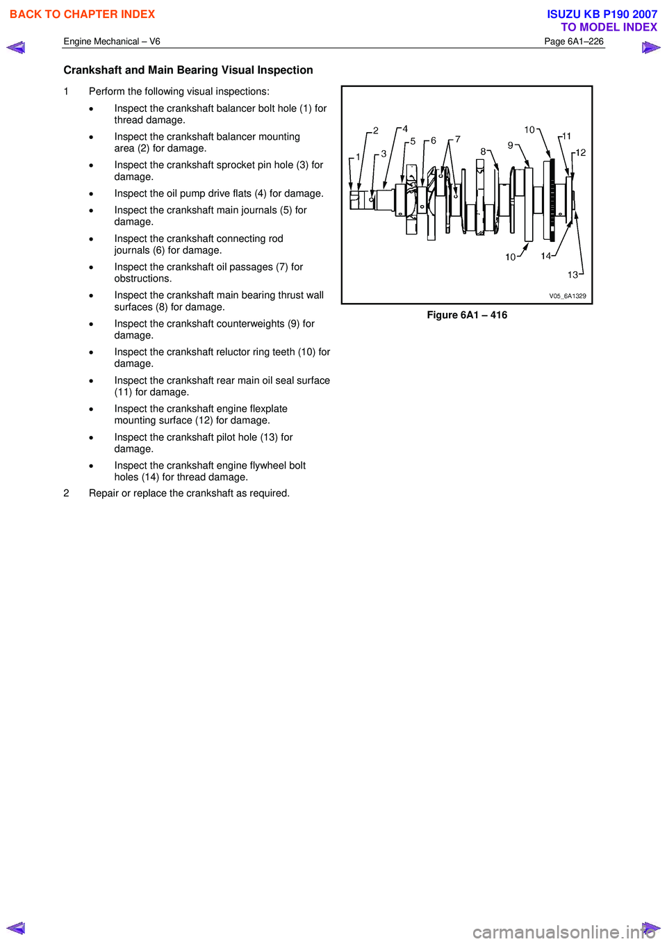
1 Perform the following visual inspections:
• Inspect the crankshaft balancer bolt hole (1) for
thread damage.
• Inspect the crankshaft balancer mounting
area (2) for damage.
• Inspect the crankshaft sprocket pin hole (3) for
damage.
• Inspect the oil pump drive flats (4) for damage.
• Inspect the crankshaft main journals (5) for
damage.
• Inspect the crankshaft connecting rod
journals (6) for damage.
• Inspect the crankshaft oil passages (7) for
obstructions.
• Inspect the crankshaft main bearing thrust wall
surfaces (8) for damage.
• Inspect the crankshaft counterweights (9) for
damage.
• Inspect the crankshaft reluctor ring teeth (10) for
damage.
• Inspect the crankshaft rear main oil seal surface
(11) for damage.
• Inspect the crankshaft engine flexplate
mounting surface (12) for damage.
• Inspect the crankshaft pilot hole (13) for
damage.
• Inspect the crankshaft engine flywheel bolt
holes (14) for thread damage.
2 Repair or replace the crankshaft as required.
Figure 6A1 – 416
BACK TO CHAPTER INDEX
TO MODEL INDEX
ISUZU KB P190 2007