2007 ISUZU KB P190 key
[x] Cancel search: keyPage 1254 of 6020
6E-220 Engine Control System (4JH1)
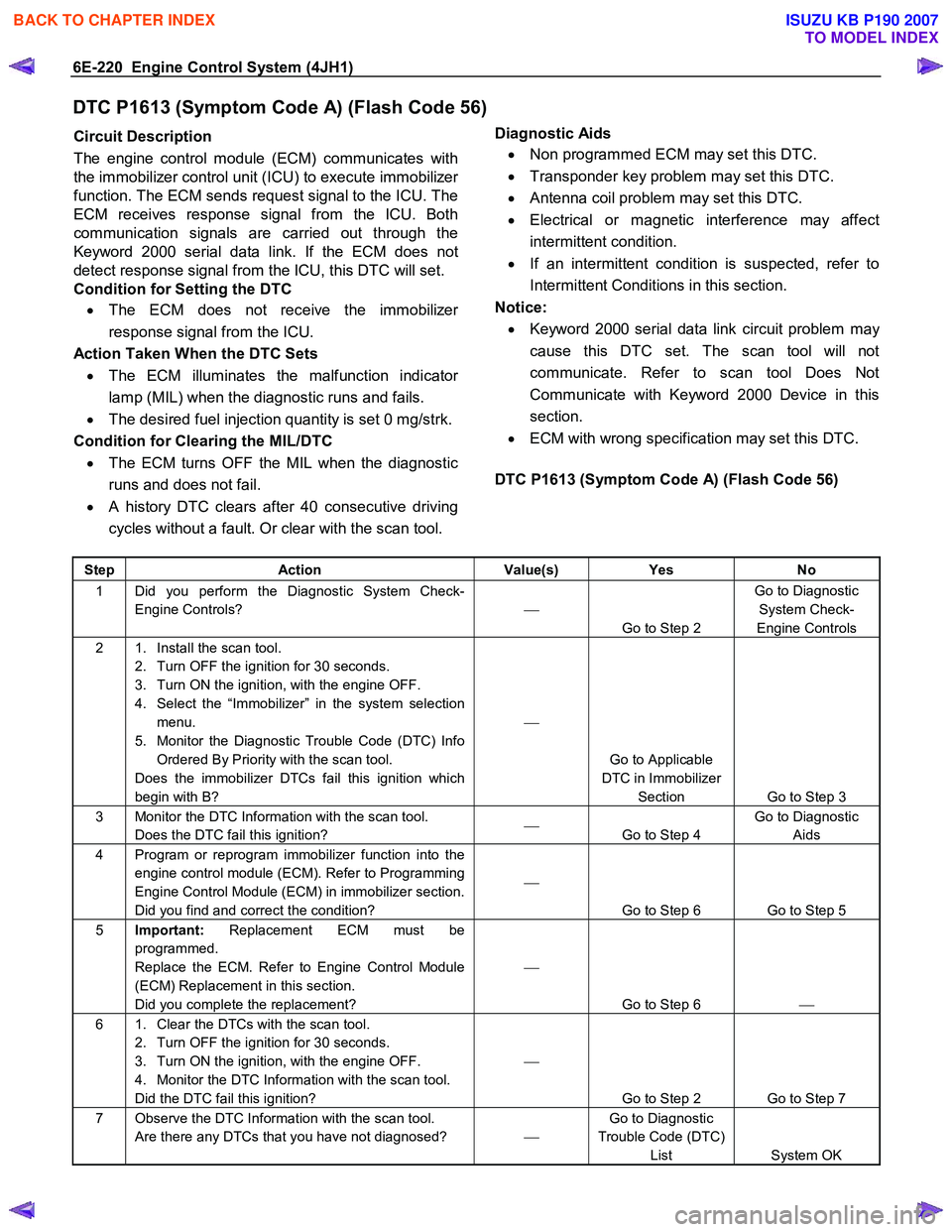
DTC P1613 (Symptom Code A) (Flash Code 56)
Circuit Description
The engine control module (ECM) communicates with
the immobilizer control unit (ICU) to execute immobilize
r
function. The ECM sends request signal to the ICU. The
ECM receives response signal from the ICU. Both
communication signals are carried out through the
Keyword 2000 serial data link. If the ECM does not
detect response signal from the ICU, this DTC will set.
Condition for Setting the DTC
• The ECM does not receive the immobilize
r
response signal from the ICU.
Action Taken When the DTC Sets • The ECM illuminates the malfunction indicato
r
lamp (MIL) when the diagnostic runs and fails.
• The desired fuel injection quantity is set 0 mg/strk.
Condition for Clearing the MIL/DTC • The ECM turns OFF the MIL when the diagnostic
runs and does not fail.
• A history DTC clears after 40 consecutive driving
cycles without a fault. Or clear with the scan tool.
Diagnostic Aids
• Non programmed ECM may set this DTC.
• Transponder key problem may set this DTC.
• Antenna coil problem may set this DTC.
• Electrical or magnetic interference may affect
intermittent condition.
• If an intermittent condition is suspected, refer to
Intermittent Conditions in this section.
Notice: • Keyword 2000 serial data link circuit problem ma
y
cause this DTC set. The scan tool will not
communicate. Refer to scan tool Does Not
Communicate with Keyword 2000 Device in this
section.
• ECM with wrong specification may set this DTC.
DTC P1613 (Symptom Code A) (Flash Code 56)
Step Action Value(s) Yes No
1 Did you perform the Diagnostic System Check-
Engine Controls?
Go to Step 2 Go to Diagnostic
System Check-
Engine Controls
2 1. Install the scan tool. 2. Turn OFF the ignition for 30 seconds.
3. Turn ON the ignition, with the engine OFF.
4. Select the “Immobilizer” in the system selection menu.
5. Monitor the Diagnostic Trouble Code (DTC) Info Ordered By Priority with the scan tool.
Does the immobilizer DTCs fail this ignition which
begin with B?
Go to Applicable
DTC in Immobilizer Section Go to Step 3
3 Monitor the DTC Information with the scan tool. Does the DTC fail this ignition?
Go to Step 4 Go to Diagnostic
Aids
4 Program or reprogram immobilizer function into the engine control module (ECM). Refer to Programming
Engine Control Module (ECM) in immobilizer section.
Did you find and correct the condition?
Go to Step 6 Go to Step 5
5 Important: Replacement ECM must be
programmed.
Replace the ECM. Refer to Engine Control Module
(ECM) Replacement in this section.
Did you complete the replacement?
Go to Step 6
6 1. Clear the DTCs with the scan tool.
2. Turn OFF the ignition for 30 seconds.
3. Turn ON the ignition, with the engine OFF.
4. Monitor the DTC Information with the scan tool.
Did the DTC fail this ignition?
Go to Step 2 Go to Step 7
7 Observe the DTC Information with the scan tool. Are there any DTCs that you have not diagnosed? Go to Diagnostic
Trouble Code (DTC) List System OK
BACK TO CHAPTER INDEX
TO MODEL INDEX
ISUZU KB P190 2007
Page 1255 of 6020
Engine Control System (4JH1) 6E-221
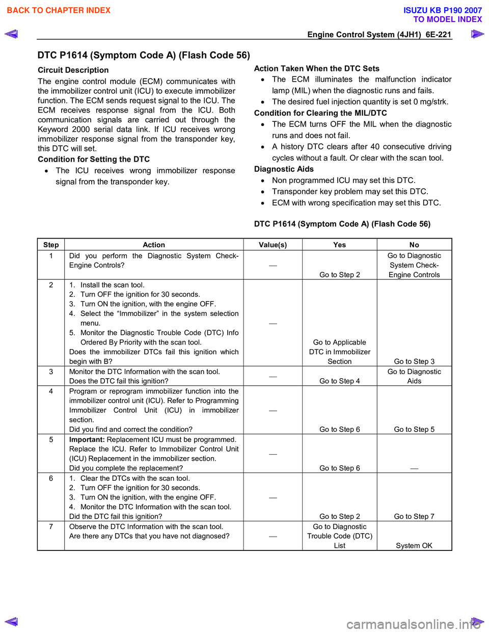
DTC P1614 (Symptom Code A) (Flash Code 56)
Circuit Description
The engine control module (ECM) communicates with
the immobilizer control unit (ICU) to execute immobilize
r
function. The ECM sends request signal to the ICU. The
ECM receives response signal from the ICU. Both
communication signals are carried out through the
Keyword 2000 serial data link. If ICU receives wrong
immobilizer response signal from the transponder key,
this DTC will set.
Condition for Setting the DTC
• The ICU receives wrong immobilizer response
signal from the transponder key.
Action Taken When the DTC Sets
• The ECM illuminates the malfunction indicato
r
lamp (MIL) when the diagnostic runs and fails.
• The desired fuel injection quantity is set 0 mg/strk.
Condition for Clearing the MIL/DTC • The ECM turns OFF the MIL when the diagnostic
runs and does not fail.
• A history DTC clears after 40 consecutive driving
cycles without a fault. Or clear with the scan tool.
Diagnostic Aids • Non programmed ICU may set this DTC.
• Transponder key problem may set this DTC.
• ECM with wrong specification may set this DTC.
DTC P1614 (Symptom Code A) (Flash Code 56)
Step Action Value(s) Yes No
1 Did you perform the Diagnostic System Check-
Engine Controls?
Go to Step 2 Go to Diagnostic
System Check-
Engine Controls
2 1. Install the scan tool. 2. Turn OFF the ignition for 30 seconds.
3. Turn ON the ignition, with the engine OFF.
4. Select the “Immobilizer” in the system selection menu.
5. Monitor the Diagnostic Trouble Code (DTC) Info Ordered By Priority with the scan tool.
Does the immobilizer DTCs fail this ignition which
begin with B?
Go to Applicable
DTC in Immobilizer Section Go to Step 3
3 Monitor the DTC Information with the scan tool. Does the DTC fail this ignition?
Go to Step 4 Go to Diagnostic
Aids
4 Program or reprogram immobilizer function into the immobilizer control unit (ICU). Refer to Programming
Immobilizer Control Unit (ICU) in immobilizer
section.
Did you find and correct the condition?
Go to Step 6 Go to Step 5
5 Important: Replacement ICU must be programmed.
Replace the ICU. Refer to Immobilizer Control Unit
(ICU) Replacement in the immobilizer section.
Did you complete the replacement?
Go to Step 6
6 1. Clear the DTCs with the scan tool.
2. Turn OFF the ignition for 30 seconds.
3. Turn ON the ignition, with the engine OFF.
4. Monitor the DTC Information with the scan tool.
Did the DTC fail this ignition?
Go to Step 2 Go to Step 7
7 Observe the DTC Information with the scan tool. Are there any DTCs that you have not diagnosed? Go to Diagnostic
Trouble Code (DTC) List System OK
BACK TO CHAPTER INDEX
TO MODEL INDEX
ISUZU KB P190 2007
Page 1289 of 6020
Engine Control System (4JH1) 6E-255
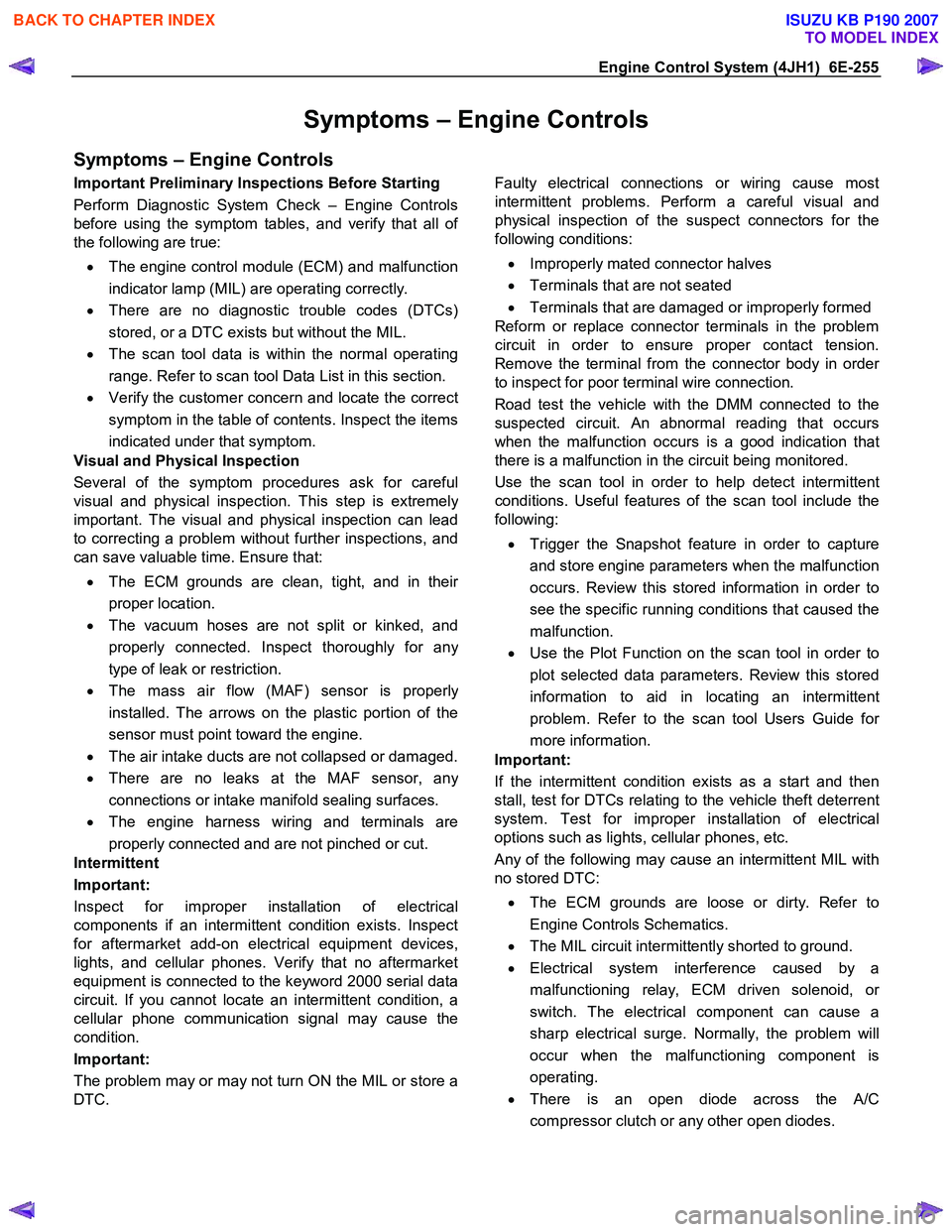
Symptoms – Engine Controls
Symptoms – Engine Controls
Important Preliminary Inspections Before Starting
Perform Diagnostic System Check – Engine Controls
before using the symptom tables, and verify that all o
f
the following are true:
• The engine control module (ECM) and malfunction
indicator lamp (MIL) are operating correctly.
• There are no diagnostic trouble codes (DTCs)
stored, or a DTC exists but without the MIL.
• The scan tool data is within the normal operating
range. Refer to scan tool Data List in this section.
• Verify the customer concern and locate the correct
symptom in the table of contents. Inspect the items
indicated under that symptom.
Visual and Physical Inspection
Several of the symptom procedures ask for careful
visual and physical inspection. This step is extremel
y
important. The visual and physical inspection can lead
to correcting a problem without further inspections, and
can save valuable time. Ensure that:
• The ECM grounds are clean, tight, and in thei
r
proper location.
• The vacuum hoses are not split or kinked, and
properly connected. Inspect thoroughly for an
y
type of leak or restriction.
• The mass air flow (MAF) sensor is properl
y
installed. The arrows on the plastic portion of the
sensor must point toward the engine.
• The air intake ducts are not collapsed or damaged.
• There are no leaks at the MAF sensor, an
y
connections or intake manifold sealing surfaces.
• The engine harness wiring and terminals are
properly connected and are not pinched or cut.
Intermittent
Important:
Inspect for improper installation of electrical
components if an intermittent condition exists. Inspect
for aftermarket add-on electrical equipment devices,
lights, and cellular phones. Verify that no aftermarket
equipment is connected to the keyword 2000 serial data
circuit. If you cannot locate an intermittent condition, a
cellular phone communication signal may cause the
condition.
Important:
The problem may or may not turn ON the MIL or store a
DTC.
Faulty electrical connections or wiring cause most
intermittent problems. Perform a careful visual and
physical inspection of the suspect connectors for the
following conditions:
• Improperly mated connector halves
• Terminals that are not seated
• Terminals that are damaged or improperly formed
Reform or replace connector terminals in the problem
circuit in order to ensure proper contact tension.
Remove the terminal from the connector body in orde
r
to inspect for poor terminal wire connection.
Road test the vehicle with the DMM connected to the
suspected circuit. An abnormal reading that occurs
when the malfunction occurs is a good indication that
there is a malfunction in the circuit being monitored.
Use the scan tool in order to help detect intermittent
conditions. Useful features of the scan tool include the
following:
• Trigger the Snapshot feature in order to capture
and store engine parameters when the malfunction
occurs. Review this stored information in order to
see the specific running conditions that caused the
malfunction.
• Use the Plot Function on the scan tool in order to
plot selected data parameters. Review this stored
information to aid in locating an intermittent
problem. Refer to the scan tool Users Guide fo
r
more information.
Important:
If the intermittent condition exists as a start and then
stall, test for DTCs relating to the vehicle theft deterrent
system. Test for improper installation of electrical
options such as lights, cellular phones, etc.
Any of the following may cause an intermittent MIL with
no stored DTC:
• The ECM grounds are loose or dirty. Refer to
Engine Controls Schematics.
• The MIL circuit intermittently shorted to ground.
• Electrical system interference caused by a
malfunctioning relay, ECM driven solenoid, o
r
switch. The electrical component can cause a
sharp electrical surge. Normally, the problem will
occur when the malfunctioning component is
operating.
• There is an open diode across the A/C
compressor clutch or any other open diodes.
BACK TO CHAPTER INDEX
TO MODEL INDEX
ISUZU KB P190 2007
Page 1310 of 6020
6E-276 Engine Control System (4JH1)
1. Connect the scan tool to the vehicle DLC, with theengine and the scan tool OFF.
2. Turn ON the scan tool.
3. Select Diagnostic > appropriate vehicle identification > Powertrain > 4JH1-TC >
Programming > Program VIN.
4. Input correct VIN reading from stamped VIN o
r
affixed VIN plate on the vehicle.
Select Lock ECU and lock the programmed VIN.
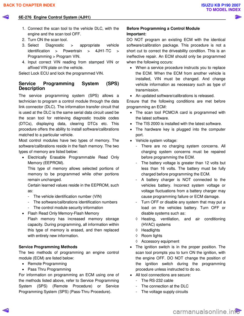
Service Programming System (SPS)
Description
The service programming system (SPS) allows a
technician to program a control module through the data
link connector (DLC). The information transfer circuit that
is used at the DLC is the same serial data circuit used be
the scan tool for retrieving diagnostic trouble codes
(DTCs), displaying data, clearing DTCs etc. This
procedure offers the ability to install software/calibrations
matched to a particular vehicle.
Most control modules have two types of memory. The
software/calibrations reside in the flash memory. The two
types of memory are listed below: • Electrically Erasable Programmable Read Onl
y
Memory (EEPROM).
This type of memory allows selected portions o
f
memory to be programmed while other portions
remain unchanged.
Certain learned values reside in the EEPROM, such as:
- The vehicle identification number (VIN)
- The software/calibrations identification numbers
- The control module security information
• Flash Read Only Memory-Flash Memory
Flash memory has increased memory storage capacity. During programming, all information within
this type of memory is erased, and then replaced
with entirely new information.
Service Programming Methods
The two methods of programming an engine control
module (ECM) are listed below: • Remote Programming
• Pass Thru Programming
For information on programming an ECM using one o
f
the methods listed above, refer to Service Programming
System (SPS) (Remote Procedure) or Service
Programming System (SPS) (Pass-Thru Procedure).
Before Programming a Control Module
Important:
DO NOT program an existing ECM with the identical
software/calibration package. This procedure is not a
short cut to correct the driveability condition. This is an
ineffective repair. An ECM should only be programmed
when the following occurs: • W hen a service procedure instructs you to replace
the ECM. W hen the ECM from another vehicle is
installed, VIN must be changed. And change
vehicle information as necessary such as type o
f
transmission.
• An updated software/calibrations is released.
Ensure that the following conditions are met before
programming an ECM: • The scan tool PCMCIA card is programmed with
the latest software.
• The TIS 2000 is installed with the latest software.
• The hardware key is plugged into the compute
r
port.
• Vehicle system voltage:
- There are no charging system concerns. All charging system concerns must be repaired
before programming the ECM.
- The battery voltage is greater than 12 volts bu
t
less than 16 volts. The battery must be fully
charged before programming the ECM.
-
A battery charger is NOT connected to the
vehicles battery. Incorrect system voltage o
r
voltage fluctuations from a battery charger may
cause programming failure or ECM damage.
- Turn OFF or disable any system that may put a load on the vehicles battery. Turn OFF o
r
disable systems such as:
◊ Heating, ventilation, and air conditioning
(HVAC) systems
◊ Headlights
◊ Room lights
◊ Accessory equipment
• The ignition switch is in the proper position. The
scan tool prompts you to turn ON the ignition, with
the engine OFF. DO NOT change the position o
f
the ignition switch during the programming
procedure unless instructed to do so.
• All tool connections are secure:
- The RS-232 cable
- The connection at the DLC
- The voltage supply circuits
BACK TO CHAPTER INDEX
TO MODEL INDEX
ISUZU KB P190 2007
Page 1481 of 6020
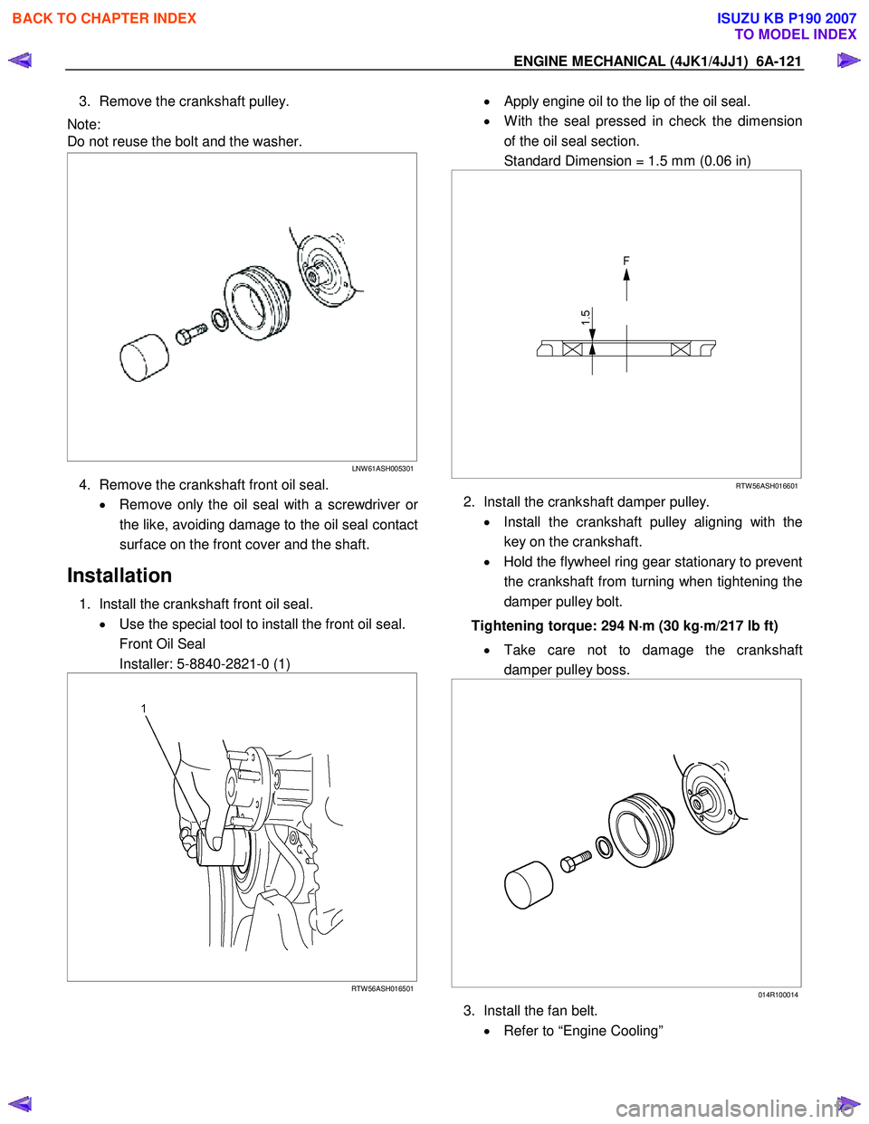
ENGINE MECHANICAL (4JK1/4JJ1) 6A-121
3. Remove the crankshaft pulley.
Note:
Do not reuse the bolt and the washer.
LNW 61ASH005301
4. Remove the crankshaft front oil seal.
• Remove only the oil seal with a screwdriver o
r
the like, avoiding damage to the oil seal contact
surface on the front cover and the shaft.
Installation
1. Install the crankshaft front oil seal. • Use the special tool to install the front oil seal.
Front Oil Seal
Installer: 5-8840-2821-0 (1)
RTW 56ASH016501
• Apply engine oil to the lip of the oil seal.
• W ith the seal pressed in check the dimension
of the oil seal section.
Standard Dimension = 1.5 mm (0.06 in)
RTW 56ASH016601
2. Install the crankshaft damper pulley.
• Install the crankshaft pulley aligning with the
key on the crankshaft.
• Hold the flywheel ring gear stationary to prevent
the crankshaft from turning when tightening the
damper pulley bolt.
Tightening torque: 294 N ⋅
⋅⋅
⋅
m (30 kg ⋅
⋅⋅
⋅
m/217 lb ft)
• Take care not to damage the crankshaft
damper pulley boss.
014R100014
3. Install the fan belt.
• Refer to “Engine Cooling”
BACK TO CHAPTER INDEX
TO MODEL INDEX
ISUZU KB P190 2007
Page 1546 of 6020
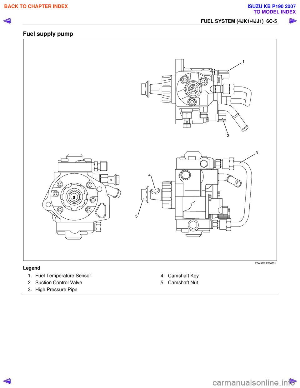
FUEL SYSTEM (4JK1/4JJ1) 6C-5
Fuel supply pump
RTW 56CLF000301
Legend 1. Fuel Temperature Sensor
2. Suction Control Valve
3. High Pressure Pipe
4. Camshaft Key
5. Camshaft Nut
BACK TO CHAPTER INDEX
TO MODEL INDEX
ISUZU KB P190 2007
Page 1558 of 6020
FUEL SYSTEM (4JK1/4JJ1) 6C-17
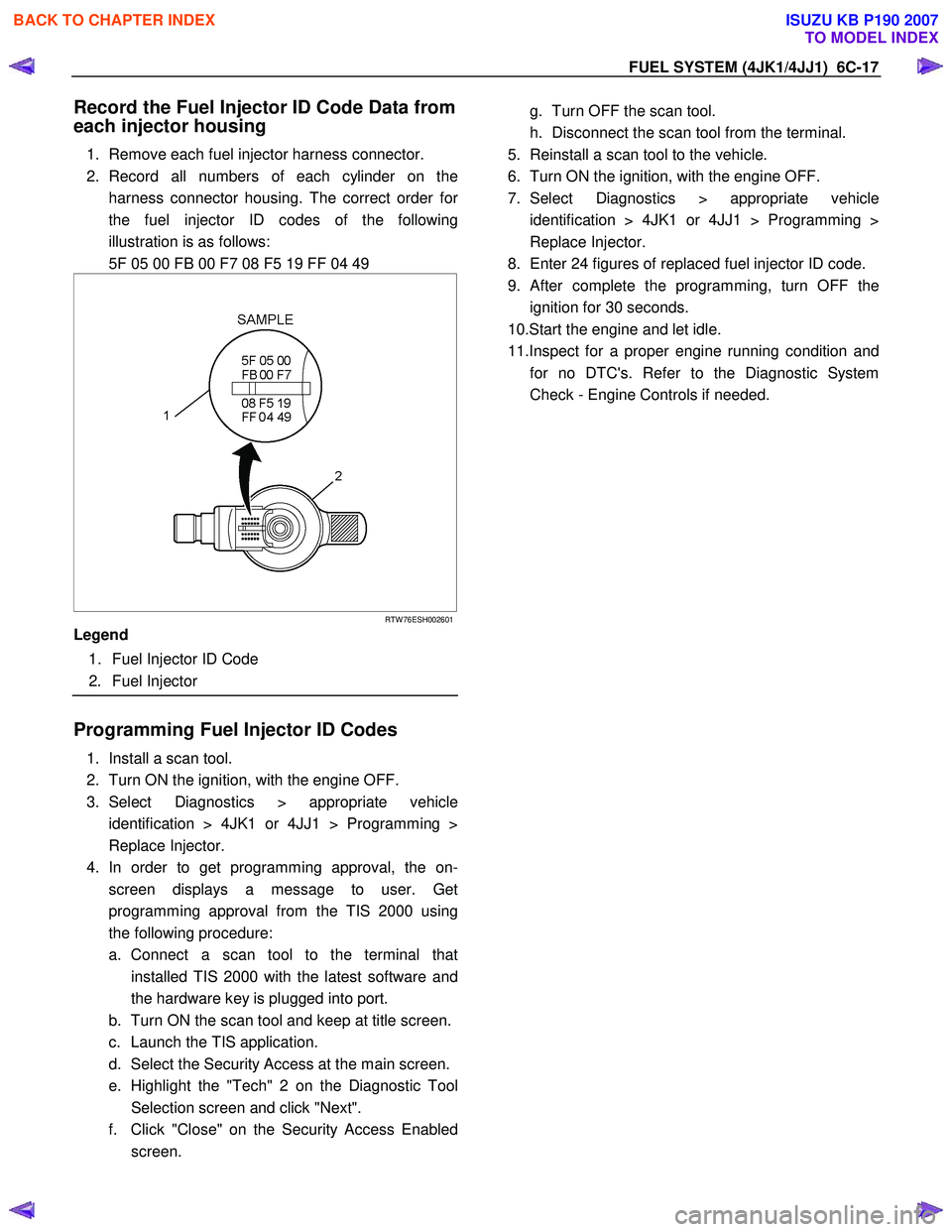
Record the Fuel Injector ID Code Data from
each injector housing
1. Remove each fuel injector harness connector.
2. Record all numbers of each cylinder on the harness connector housing. The correct order fo
r
the fuel injector ID codes of the following
illustration is as follows:
5F 05 00 FB 00 F7 08 F5 19 FF 04 49
RTW 76ESH002601
Legend
1. Fuel Injector ID Code
2. Fuel Injector
Programming Fuel Injector ID Codes
1. Install a scan tool.
2. Turn ON the ignition, with the engine OFF.
3. Select Diagnostics > appropriate vehicle identification > 4JK1 or 4JJ1 > Programming >
Replace Injector.
4. In order to get programming approval, the on- screen displays a message to user. Get
programming approval from the TIS 2000 using
the following procedure:
a. Connect a scan tool to the terminal that installed TIS 2000 with the latest software and
the hardware key is plugged into port.
b. Turn ON the scan tool and keep at title screen.
c. Launch the TIS application.
d. Select the Security Access at the main screen.
e. Highlight the "Tech" 2 on the Diagnostic Tool Selection screen and click "Next".
f. Click "Close" on the Security Access Enabled screen.
g. Turn OFF the scan tool.
h. Disconnect the scan tool from the terminal.
5. Reinstall a scan tool to the vehicle.
6. Turn ON the ignition, with the engine OFF.
7. Select Diagnostics > appropriate vehicle identification > 4JK1 or 4JJ1 > Programming >
Replace Injector.
8. Enter 24 figures of replaced fuel injector ID code.
9.
After complete the programming, turn OFF the
ignition for 30 seconds.
10.Start the engine and let idle.
11.Inspect for a proper engine running condition and for no DTC's. Refer to the Diagnostic System
Check - Engine Controls if needed.
BACK TO CHAPTER INDEX
TO MODEL INDEX
ISUZU KB P190 2007
Page 1574 of 6020
FUEL SYSTEM (4JK1/4JJ1) 6C-33
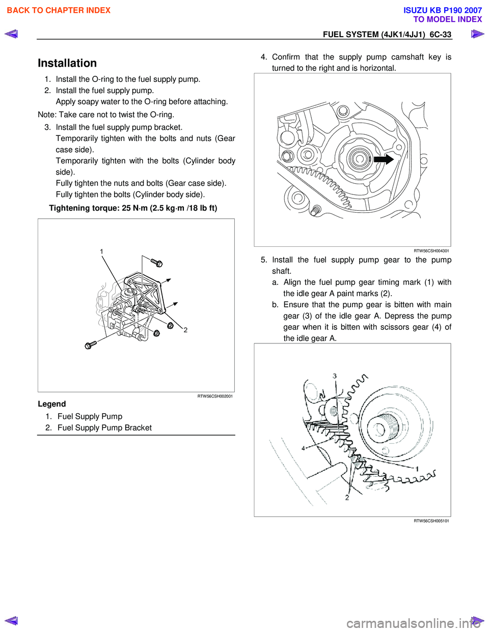
Installation
1. Install the O-ring to the fuel supply pump.
2. Install the fuel supply pump.
Apply soapy water to the O-ring before attaching.
Note: Take care not to twist the O-ring. 3. Install the fuel supply pump bracket.
Temporarily tighten with the bolts and nuts (Gea
r
case side).
Temporarily tighten with the bolts (Cylinder bod
y
side).
Fully tighten the nuts and bolts (Gear case side).
Fully tighten the bolts (Cylinder body side).
Tightening torque: 25 N ⋅
⋅⋅
⋅
m (2.5 kg ⋅
⋅⋅
⋅
m /18 lb ft)
RTW 56CSH002001
Legend
1. Fuel Supply Pump
2. Fuel Supply Pump Bracket
4. Confirm that the supply pump camshaft key is
turned to the right and is horizontal.
RTW 56CSH004301
5. Install the fuel supply pump gear to the pump
shaft.
a.
Align the fuel pump gear timing mark (1) with
the idle gear A paint marks (2).
b. Ensure that the pump gear is bitten with main gear (3) of the idle gear A. Depress the pump
gear when it is bitten with scissors gear (4) o
f
the idle gear A.
RTW 56CSH005101
BACK TO CHAPTER INDEX
TO MODEL INDEX
ISUZU KB P190 2007