2007 ISUZU KB P190 engine mount
[x] Cancel search: engine mountPage 920 of 6020

ENGINE MECHANICAL 6A – 115
RTW 46ASH002201
4JA1T(L):
4. Tighten the injection pump bolts to the specified torque.
5. Install the injection pump bracket (4) and the bracket bolts (5) and (6) to the cylinder body. Temporarily tighten
the bracket bolts.
6. Tighten the bracket bolts (5) to the specified torque.
7. Tighten the bracket bolts (6) to the specified torque.
Injection pump Bracket Bolt Torque (6) N·m(kg·m/lbft)
19 (1.9/14)
Injection pump Bracket Bolt Torque (5) N·m(kg·m/lbft)
40 (4.1/30)
030RY00007
24. Water Pump
1. Apply the recommended liquid gasket or its equivalent to the water pump at the position shown in the
illustration.
Do not apply an excessive amount of liquid gasket.
2. Tighten the water pump bolts to the specified torque.
W ater Pump Bolt Torque N·m(kg·m/lbft)
20 (2.0/14)
25.Timing Gear Case Cover
1.
Align the gear case with the timing gear case knock pin
and then install the timing gear case cover.
2. Tighten the gear case cover bolts to the specified torque.
Gear Case Cover Bolt Torque N·m(kg·m/lbft)
M8 19 (1.9/14)
M12 76 (7.7/56)
26. Crankshaft Damper Pulley
Tighten the crankshaft damper pulley bolt to the specified
torque.
Note:
Hold the flywheel ring gear stationary to prevent the
crankshaft from turning when tightening the damper
pulley bolt.
Crankshaft Damper Pulley Bolt Torque N·m(kg·m/lbft)
206 (21/152)
Take care not to damage the crankshaft damper pulley
boss.
014R100014
020R300004
BACK TO CHAPTER INDEX
TO MODEL INDEX
ISUZU KB P190 2007
Page 923 of 6020

6A – 118 ENGINE MECHANICAL
INSTALLATION
EXTERNAL PARTS
RTW 36AMF000701
Installation Steps
1.
Exhaust Manifold 18. Engine Mounting Bracket and
2.
Oil Cooler with Oil Filter Foot
3. Generator Bracket 19. Intake Manifold
4. W ater Inlet Pipe 20. Power Steering Oil Pump
5.
Generator and Adjusting Plate Bracket
6.
Vacuum Pump Oil Return Hose 21. Fuel Injection Pipe with Clip
7.
Compressor Bracket 22. Fuel Filter Bracket (Except
EURO III)
8. Turbocharger 23. Fuel Filter Assembly (Except
EURO III)
9. Catalytic Converter 24. Oil Level Gauge
10. Heat Protector 25. EGR Valve
11. Cooling Fan Pulley 26-1. EGR Pipe
12. Oil Cooler W ater Pipe 26-2. EGR Cooler (EURO III model
only)
13. Fuel Leak Off Pipe 27. Intake Pipe and Throttle Body
(4JA1TC/4JH1TC only)
14. Oil Pressure W arning Switch 28. Clutch Assembly or Flex Plate
15. Starter Motor
16. Injection Pump
17. Injection Pump Cover
BACK TO CHAPTER INDEX
TO MODEL INDEX
ISUZU KB P190 2007
Page 948 of 6020

6B – 4 ENGINE COOLING
GENERAL DESCRIPTION
COOLANT FLOW
RTW 66ALF000101
The engine cooling system consists of the radiator, the water pump, the cooling fan, and the thermostat.
To quickly increase cold engine coolant temperature for smooth engine operation, the coolant is circulated by the
water pump and thermostat through the bypass hose and back to the cylinder body.
The coolant does not circulate through the radiator.
W hen the coolant temperature reaches specified value, the thermostat will begin to open and a gradually increasing
amount of coolant will circulate through the radiator.
The thermostat will be fully open when the coolant temperature reaches specified value. All of the coolant is now
circulating through the radiator for effective engine cooling.
BACK TO CHAPTER INDEX
TO MODEL INDEX
ISUZU KB P190 2007
Page 1004 of 6020

ENGINE ELECTRICAL 6D – 3
GENERAL DESCRIPTION
GENERATOR STARTER MOTOR
066L300004 065L300002
The basic charging system is the IC integral regulator charging system. The internal components are connected
electrically as shown in charging circuit diagram.
The generator features a solid state regulator that is mounted inside the generator. All regulator components are
enclosed into a solid mold, and this unit along with the brush holder assembly is attached to the slip ring end frame.
The generator voltage setting cannot be adjusted.
The starter motor circuit is composed of a 4-pole 4-brush type direct current series motor. The starter motor circuit
utilizes negative ground polarity.
BACK TO CHAPTER INDEX
TO MODEL INDEX
ISUZU KB P190 2007
Page 1064 of 6020

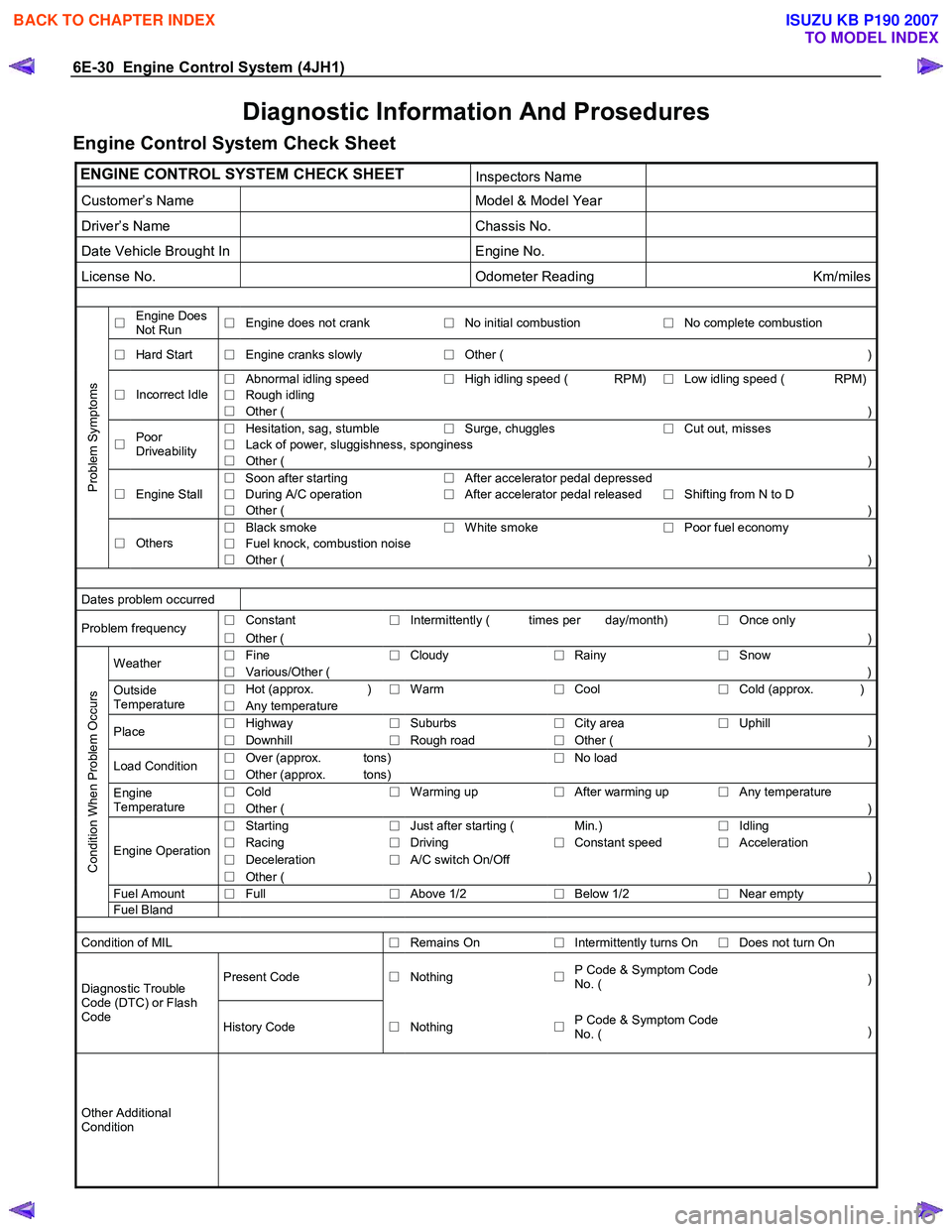
6E-30 Engine Control System (4JH1)
Diagnostic Information And Prosedures
Engine Control System Check Sheet
ENGINE CONTROL SYSTEM CHECK SHEET Inspectors Name
Customer’s Name Model & Model Year
Driver’s Name Chassis No.
Date Vehicle Brought In Engine No.
License No. Odometer Reading Km/miles
□ Engine Does
Not Run □
Engine does not crank
□No initial combustion
□ No complete combustion
□
Hard Start
□ Engine cranks slowly
□Other ( )
□
Abnormal idling speed
□High idling speed ( RPM)
□ Low idling speed ( RPM)
□
Rough idling □
Incorrect Idle
□ Other ( )
□
Hesitation, sag, stumble
□Surge, chuggles
□ Cut out, misses
□
Lack of power, sluggishness, sponginess □
Poor
Driveability □ Other ( )
□ Soon after starting
□After accelerator pedal depressed
Engine Stall
□ During A/C operation
□After accelerator pedal released
□ Shifting from N to D □
□ Other ( )
□
Black smoke
□White smoke
□ Poor fuel economy
□
Fuel knock, combustion noise
Problem Symptoms
□
Others
□ Other ( )
Dates problem occurred
□
Constant
□Intermittently ( times per day/month)
□ Once only Problem frequency
□ Other (
)
□ Fine
□Cloudy
□Rainy
□ Snow Weather
□ Various/Other (
)
□ Hot (approx. )
□Warm
□Cool
□ Cold (approx. )Outside
Temperature □ Any temperature
□
Highway
□Suburbs
□City area
□ Uphill Place
□ Downhill
□Rough road
□Other (
)
□ Over (approx. tons)
□No load
Load Condition
□ Other (approx. tons)
□ Cold
□Warming up
□After warming up
□ Any temperature Engine
Temperature □ Other ( )
□
Starting
□Just after starting ( Min.)
□ Idling
□
Racing
□Driving
□Constant speed
□ Acceleration
□
Deceleration
□A/C switch On/Off Engine Operation
□ Other ( )
Fuel Amount
□ Full
□Above 1/2
□Below 1/2
□ Near empty
Condition When Problem Occurs
Fuel
Bland
Condition of MIL
□Remains On
□Intermittently turns On
□ Does not turn On
Present Code
□Nothing
□P Code & Symptom Code
No. ( )Diagnostic Trouble
Code (DTC) or Flash
Code History Code □Nothing
□P Code & Symptom Code
No. ( )
Other Additional
Condition
BACK TO CHAPTER INDEX
TO MODEL INDEX
ISUZU KB P190 2007
Page 1072 of 6020

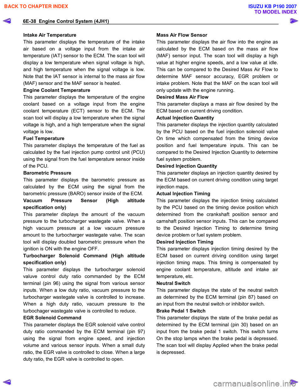
6E-38 Engine Control System (4JH1)
Intake Air Temperature
This parameter displays the temperature of the intake
air based on a voltage input from the intake ai
r
temperature (IAT) sensor to the ECM. The scan tool will
display a low temperature when signal voltage is high,
and high temperature when the signal voltage is low.
Note that the IAT sensor is internal to the mass air flo
w
(MAF) sensor and the MAF sensor is heated.
Engine Coolant Temperature
This parameter displays the temperature of the engine
coolant based on a voltage input from the engine
coolant temperature (ECT) sensor to the ECM. The
scan tool will display a low temperature when the signal
voltage is high, and a high temperature when the signal
voltage is low.
Fuel Temperature
This parameter displays the temperature of the fuel as
calculated by the fuel injection pump control unit (PCU)
using the signal from the fuel temperature sensor inside
of the PCU.
Barometric Pressure
This parameter displays the barometric pressure as
calculated by the ECM using the signal from the
barometric pressure (BARO) sensor inside of the ECM.
Vacuum Pressure Sensor (High altitude
specification only)
This parameter displays the amount of the vacuum
pressure to the turbocharger wastegate valve. W hen a
high vacuum pressure at a low vacuum pressure
amount to the turbocharger wastegate valve. The scan
tool will display doubled barometric pressure when the
ignition is ON with the engine OFF.
Turbocharger Solenoid Command (High altitude
specification only)
This parameter displays the turbocharger solenoid
valuve control duty ratio commanded by the ECM
terminal (pin 96) using the signal from various senso
r
inputs. W hen a low duty ratio, vacuum pressure to the
turbocharger wastegate valve is controlled to increase.
W hen a high duty ratio, vacuum pressure to the
turbochager wastegate valve is controlled to reduce.
EGR Solenoid Command
This parameter displays the EGR solenoid valve control
duty ratio commanded by the ECM terminal (pin 97)
using the signal from engine speed, and injection
volume and various sensor inputs. W hen a small dut
y
ratio, the EGR valve is controlled to close. W hen a large
duty ratio, the EGR valve is controlled to open.
Mass Air Flow Sensor
This parameter displays the air flow into the engine as
calculated by the ECM based on the mass air flo
w
(MAF) sensor input. The scan tool will display a high
value at higher engine speeds, and a low value at idle.
This can be compared to the Desired Mass Air Flow to
determine MAF sensor accuracy, EGR problem o
r
intake problem. Note that the MAF on the scan tool will
only update with the engine running.
Desired Mass Air Flow
This parameter displays a mass air flow desired by the
ECM based on current driving condition.
Actual Injection Quantity
This parameter displays the injection quantity calculated
by the PCU based on the fuel injection solenoid valve
On time which compensated from the timing device
position and fuel temperature inputs. This can be
compared to the Desired Injection Quantity to determine
fuel system problem.
Desired Injection Quantity
This parameter displays an injection quantity desired b
y
the ECM based on current driving condition using target
injection maps.
Actual Injection Timing
This parameter displays the injection timing calculated
by the PCU based on the timing device position which
determined from the crankshaft position sensor and
camshaft position sensor inputs. This can be compared
to the Desired Injection Timing to determine timing
device problem or fuel system problem.
Desired Injection Timing
This parameter displays injection timing desired by the
ECM based on current driving condition using target
injection timing maps. This timing is compensated b
y
engine coolant temperature, altitude and intake ai
r
temperature, etc.
Neutral Switch
This parameter displays the state of the neutral switch
as determined by the ECM terminal (pin 87) based on
an input from the neutral switch or inhibitor switch.
Brake Pedal 1 Switch
This parameter displays the state of the brake pedal as
determined by the ECM terminal (pin 30) based on an
input from the brake pedal 1 switch. This switch turns
On the stop lamps when the brake pedal is depressed.
The scan tool will display Applied when the brake pedal
is depressed.
BACK TO CHAPTER INDEX
TO MODEL INDEX
ISUZU KB P190 2007
Page 1081 of 6020

Engine Control System (4JH1) 6E-47
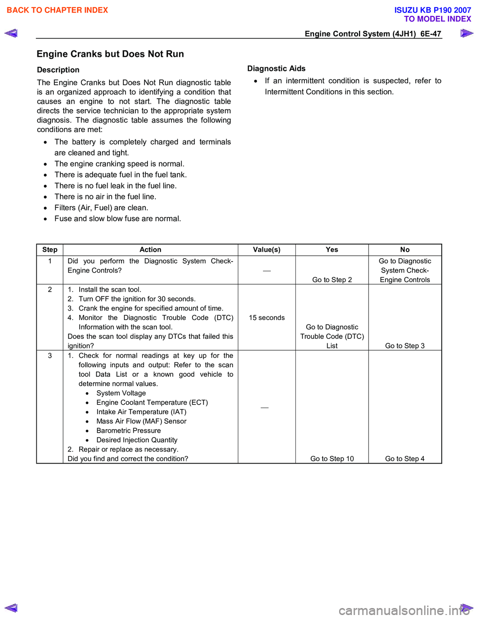
Engine Cranks but Does Not Run
Description
The Engine Cranks but Does Not Run diagnostic table
is an organized approach to identifying a condition that
causes an engine to not start. The diagnostic table
directs the service technician to the appropriate system
diagnosis. The diagnostic table assumes the following
conditions are met:
• The battery is completely charged and terminals
are cleaned and tight.
• The engine cranking speed is normal.
• There is adequate fuel in the fuel tank.
• There is no fuel leak in the fuel line.
• There is no air in the fuel line.
• Filters (Air, Fuel) are clean.
• Fuse and slow blow fuse are normal.
Diagnostic Aids
• If an intermittent condition is suspected, refer to
Intermittent Conditions in this section.
Step Action Value(s) Yes No
1 Did you perform the Diagnostic System Check-
Engine Controls?
Go to Step 2 Go to Diagnostic
System Check-
Engine Controls
2 1. Install the scan tool. 2. Turn OFF the ignition for 30 seconds.
3. Crank the engine for specified amount of time.
4. Monitor the Diagnostic Trouble Code (DTC) Information with the scan tool.
Does the scan tool display any DTCs that failed this
ignition? 15 seconds
Go to Diagnostic
Trouble Code (DTC) List Go to Step 3
3 1. Check for normal readings at key up for the
following inputs and output: Refer to the scan
tool Data List or a known good vehicle to
determine normal values. • System Voltage
• Engine Coolant Temperature (ECT)
• Intake Air Temperature (IAT)
• Mass Air Flow (MAF) Sensor
• Barometric Pressure
• Desired Injection Quantity
2. Repair or replace as necessary.
Did you find and correct the condition?
Go to Step 10 Go to Step 4
BACK TO CHAPTER INDEX
TO MODEL INDEX
ISUZU KB P190 2007
Page 1083 of 6020

Engine Control System (4JH1) 6E-49
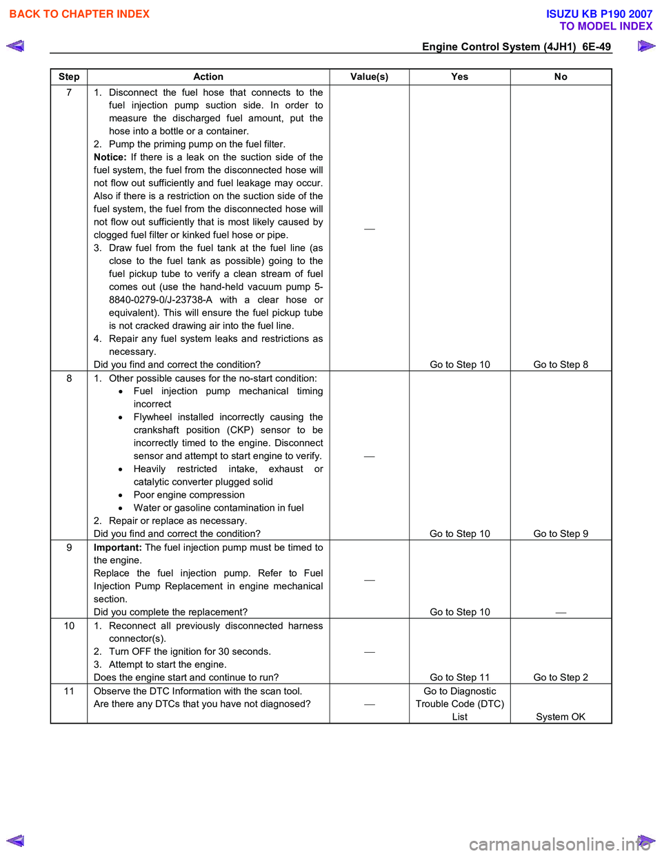
Step Action Value(s) Yes No
7 1. Disconnect the fuel hose that connects to the
fuel injection pump suction side. In order to
measure the discharged fuel amount, put the
hose into a bottle or a container.
2. Pump the priming pump on the fuel filter.
Notice: If there is a leak on the suction side of the
fuel system, the fuel from the disconnected hose will
not flow out sufficiently and fuel leakage may occur.
Also if there is a restriction on the suction side of the
fuel system, the fuel from the disconnected hose will
not flow out sufficiently that is most likely caused by
clogged fuel filter or kinked fuel hose or pipe.
3. Draw fuel from the fuel tank at the fuel line (as close to the fuel tank as possible) going to the
fuel pickup tube to verify a clean stream of fuel
comes out (use the hand-held vacuum pump 5-
8840-0279-0/J-23738-A with a clear hose or
equivalent). This will ensure the fuel pickup tube
is not cracked drawing air into the fuel line.
4. Repair any fuel system leaks and restrictions as necessary.
Did you find and correct the condition?
Go to Step 10 Go to Step 8
8 1. Other possible causes for the no-start condition: • Fuel injection pump mechanical timing
incorrect
• Flywheel installed incorrectly causing the
crankshaft position (CKP) sensor to be
incorrectly timed to the engine. Disconnect
sensor and attempt to start engine to verify.
• Heavily restricted intake, exhaust or
catalytic converter plugged solid
• Poor engine compression
• W ater or gasoline contamination in fuel
2. Repair or replace as necessary.
Did you find and correct the condition?
Go to Step 10 Go to Step 9
9 Important: The fuel injection pump must be timed to
the engine.
Replace the fuel injection pump. Refer to Fuel
Injection Pump Replacement in engine mechanical
section.
Did you complete the replacement?
Go to Step 10
10 1. Reconnect all previously disconnected harness
connector(s).
2. Turn OFF the ignition for 30 seconds.
3. Attempt to start the engine.
Does the engine start and continue to run?
Go to Step 11 Go to Step 2
11 Observe the DTC Information with the scan tool. Are there any DTCs that you have not diagnosed? Go to Diagnostic
Trouble Code (DTC) List System OK
BACK TO CHAPTER INDEX
TO MODEL INDEX
ISUZU KB P190 2007