2007 ISUZU KB P190 Wiring
[x] Cancel search: WiringPage 1296 of 6020
6E-262 Engine Control System (4JH1)
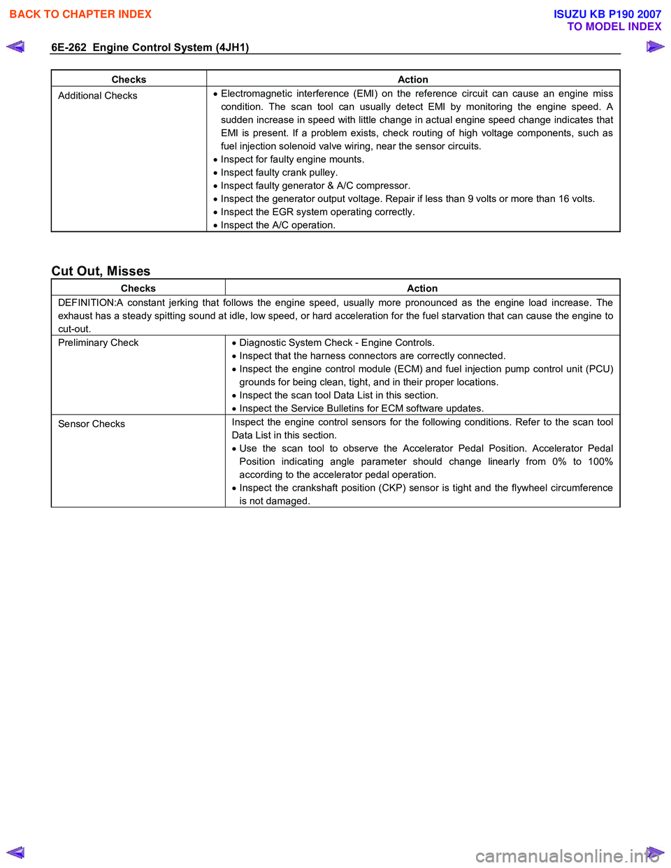
Checks Action
Additional Checks •
Electromagnetic interference (EMI) on the reference circuit can cause an engine miss
condition. The scan tool can usually detect EMI by monitoring the engine speed. A
sudden increase in speed with little change in actual engine speed change indicates that
EMI is present. If a problem exists, check routing of high voltage components, such as
fuel injection solenoid valve wiring, near the sensor circuits.
• Inspect for faulty engine mounts.
• Inspect faulty crank pulley.
• Inspect faulty generator & A/C compressor.
• Inspect the generator output voltage. Repair if less than 9 volts or more than 16 volts.
• Inspect the EGR system operating correctly.
• Inspect the A/C operation.
Cut Out, Misses
Checks Action
DEFINITION:A constant jerking that follows the engine speed, usually more pronounced as the engine load increase. The
exhaust has a steady spitting sound at idle, low speed, or hard acceleration for the fuel starvation that can cause the engine to
cut-out.
Preliminary Check • Diagnostic System Check - Engine Controls.
• Inspect that the harness connectors are correctly connected.
• Inspect the engine control module (ECM) and fuel injection pump control unit (PCU)
grounds for being clean, tight, and in their proper locations.
• Inspect the scan tool Data List in this section.
• Inspect the Service Bulletins for ECM software updates.
Sensor Checks Inspect the engine control sensors for the following conditions. Refer to the scan tool
Data List in this section.
• Use the scan tool to observe the Accelerator Pedal Position. Accelerator Pedal
Position indicating angle parameter should change linearly from 0% to 100%
according to the accelerator pedal operation.
• Inspect the crankshaft position (CKP) sensor is tight and the flywheel circumference
is not damaged.
BACK TO CHAPTER INDEX
TO MODEL INDEX
ISUZU KB P190 2007
Page 1297 of 6020
Engine Control System (4JH1) 6E-263
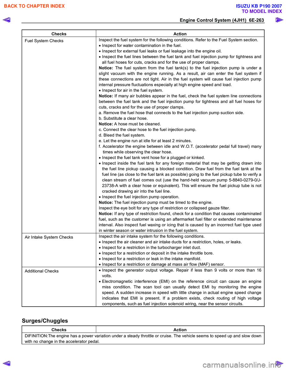
Checks Action
Fuel System Checks Inspect the fuel system for the following conditions. Refer to the Fuel System section.
• Inspect for water contamination in the fuel.
• Inspect for external fuel leaks or fuel leakage into the engine oil.
• Inspect the fuel lines between the fuel tank and fuel injection pump for tightness and
all fuel hoses for cuts, cracks and for the use of proper clamps.
Notice: The fuel system from the fuel tank(s) to the fuel injection pump is under a
slight vacuum with the engine running. As a result, air can enter the fuel system if
these connections are not tight. Air in the fuel system will cause fuel injection pump
internal pressure fluctuations especially at high engine speed and load.
• Inspect for air in the fuel system.
Notice: If many air bubbles appear in the fuel, check the fuel system line connections
between the fuel tank and the fuel injection pump for tightness and all fuel hoses for
cuts, cracks and for the use of proper clamps.
a. Remove the fuel hose that connects to the fuel injection pump suction side.
b. Substitute a clear hose.
Notice: A hose must be cleaned.
c. Connect the clear hose to the fuel injection pump.
d. Bleed the fuel system.
e. Let the engine run at idle for at least 2 minutes.
f. Accelerator the engine between idle and W .O.T. (accelerator pedal full travel) many times while observing the clear hose.
• Inspect the fuel tank vent hose for a plugged or kinked.
• Inspect inside the fuel tank for any foreign material that may be getting drawn into
the fuel line pickup causing a blocked condition. Draw fuel from the fuel tank at the
fuel line (as close to the fuel tank as possible) going to the fuel pickup tube to verify a
clean stream of fuel comes out (use the hand-held vacuum pump 5-8840-0279-0/J-
23738-A with a clear hose or equivalent). This will ensure the fuel pickup tube is not
cracked drawing air into the fuel line.
• Inspect the fuel injection pump operation.
Notice: The fuel injection pump must be timed to the engine.
Inspect the eye bolt for any type of restriction or collapsed gauze filter.
Notice: If any type of restriction found, check for a condition that causes contaminated
fuel, such as the customer is using an aftermarket fuel filter or extended maintenance
interval. Also inspect fuel waxing or icing that is caused by an incorrect fuel type used
in winter season or water intrusion in the fuel system.
Air Intake System Checks Inspect the air intake system for the following conditions.
• Inspect the air cleaner and air intake ducts for a restriction, holes, or leaks.
• Inspect for a restriction in the turbocharger inlet duct.
• Inspect for a restriction or deposit in the intake throttle bore.
• Inspect for a restriction or leak in the intake manifold.
• Inspect for a restriction or damage at mass air flow (MAF) sensor.
Additional Checks •
Inspect the generator output voltage. Repair if less than 9 volts or more than 16
volts.
• Electromagnetic interference (EMI) on the reference circuit can cause an engine
miss condition. The scan tool can usually detect EMI by monitoring the engine
speed. A sudden increase in speed with little change in actual engine speed change
indicates that EMI is present. If a problem exists, check routing of high voltage
components, such as fuel injection solenoid wiring, near the sensor circuits.
Surges/Chuggles
Checks Action
DIFINITION:The engine has a power variation under a steady throttle or cruise. The vehicle seems to speed up and slow down
with no change in the accelerator pedal.
BACK TO CHAPTER INDEX
TO MODEL INDEX
ISUZU KB P190 2007
Page 1371 of 6020
ENGINE MECHANICAL (4JK1/4JJ1) 6A-11
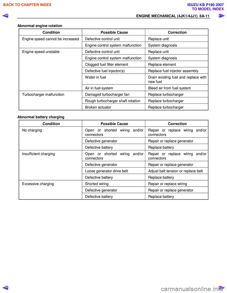
Abnormal engine rotation
Condition Possible Cause Correction
Defective control unit Replace unit Engine speed cannot be increased
Engine control system malfunction System diagnosis
Defective control unit Replace unit
Engine control system malfunction System diagnosis
Clogged fuel filter element Replace element
Defective fuel injector(s) Replace fuel injector assembly
W ater in fuel Drain existing fuel and replace with
new fuel
Engine speed unstable
Air in fuel system Bleed air from fuel system
Damaged turbocharger fan Replace turbocharger
Rough turbocharger shaft rotation Replace turbocharger
Turbocharger malfunction
Broken actuator Replace turbocharger
Abnormal battery charging
Condition Possible Cause Correction
Open or shorted wiring and/or
connectors Repair or replace wiring and/or
connectors
Defective generator Repair or replace generator
No charging
Defective battery Replace battery
Open or shorted wiring and/or
connectors Repair or replace wiring and/or
connectors
Defective generator Repair or replace generator
Loose generator drive belt Adjust belt tension or replace belt
Insufficient charging
Defective battery Replace battery
Shorted wiring Repair or replace wiring
Defective generator Repair or replace generator
Excessive charging
Defective battery Replace battery
BACK TO CHAPTER INDEX
TO MODEL INDEX
ISUZU KB P190 2007
Page 1432 of 6020
6A-72 ENGINE MECHANICAL (4JK1/4JJ1)
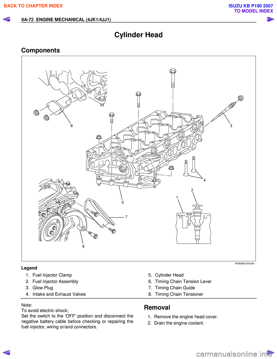
Cylinder Head
Components
RTW 56ALF001001
Legend 1. Fuel Injector Clamp
2. Fuel Injector Assembly
3. Glow Plug
4. Intake and Exhaust Valves 5. Cylinder Head
6. Timing Chain Tension Lever
7. Timing Chain Guide
8. Timing Chain Tensioner
Note:
To avoid electric shock;
Set the switch to the 'OFF' position and disconnect the
negative battery cable before checking or repairing the
fuel injector, wiring or/and connectors. Removal
1. Remove the engine head cover.
2. Drain the engine coolant.
BACK TO CHAPTER INDEX
TO MODEL INDEX
ISUZU KB P190 2007
Page 1556 of 6020
FUEL SYSTEM (4JK1/4JJ1) 6C-15
The fuel system consists of many tiny holes and spaces
that allow the movement of fuel from one place to
another. These holes and spaces are milled to
extremely high precision. This is especially true of the
fuel injector.
The fuel injector is very sensitive to foreign material.
Foreign material will result in fuel system breakdown.
Exercise great care not to allow the entry of foreign
material into the fuel system or fuel injector during the
removal and installation procedure.
Note: To avoid electric shock;
Set the switch to the 'OFF' position and disconnect the
negative battery cable before checking or repairing the
fuel injector, wiring or/and connectors.
Removal
1. Remove the cylinder head cover.
Refer to the removal procedure for the cylinde
r
head cover in this manual.
Remove the attachment bolt of the engine oil gauge
guide tube.
2. Loosen the fuel injector clamp fixing bolts and
remove the fuel injector.
If the fuel injector is difficult to remove, use the remover. Use a screwdriver to force the fuel
injector clamp off the fuel injector.
Note: Do not remove the fuel injector sleeve.
Note: Cover the areas exposed during parts removal to
prevent the entry of foreign material into the fuel
system.
3. Mark each fuel injector with the number of the cylinder from which it was removed. Store the fuel
injector in a safe place. Position the fuel injector so
that the nozzle is protected.
Note: Do not tamper with the electromagnetic portion of
the fuel injector. Reduced electromagnetic function will
result in injector failure.
Note: After replacement of the fuel injector, perform the
following procedure.
• All fuel injectors are replaced:
Remove the fuel injector ID code label on the cylinder head cover.
• Any fuel injector(s) is replaced:
Black out the replaced cylinder of the fuel injecto
r
ID code on the fuel injector ID code label with a
marking pen or equivalent.
Installation
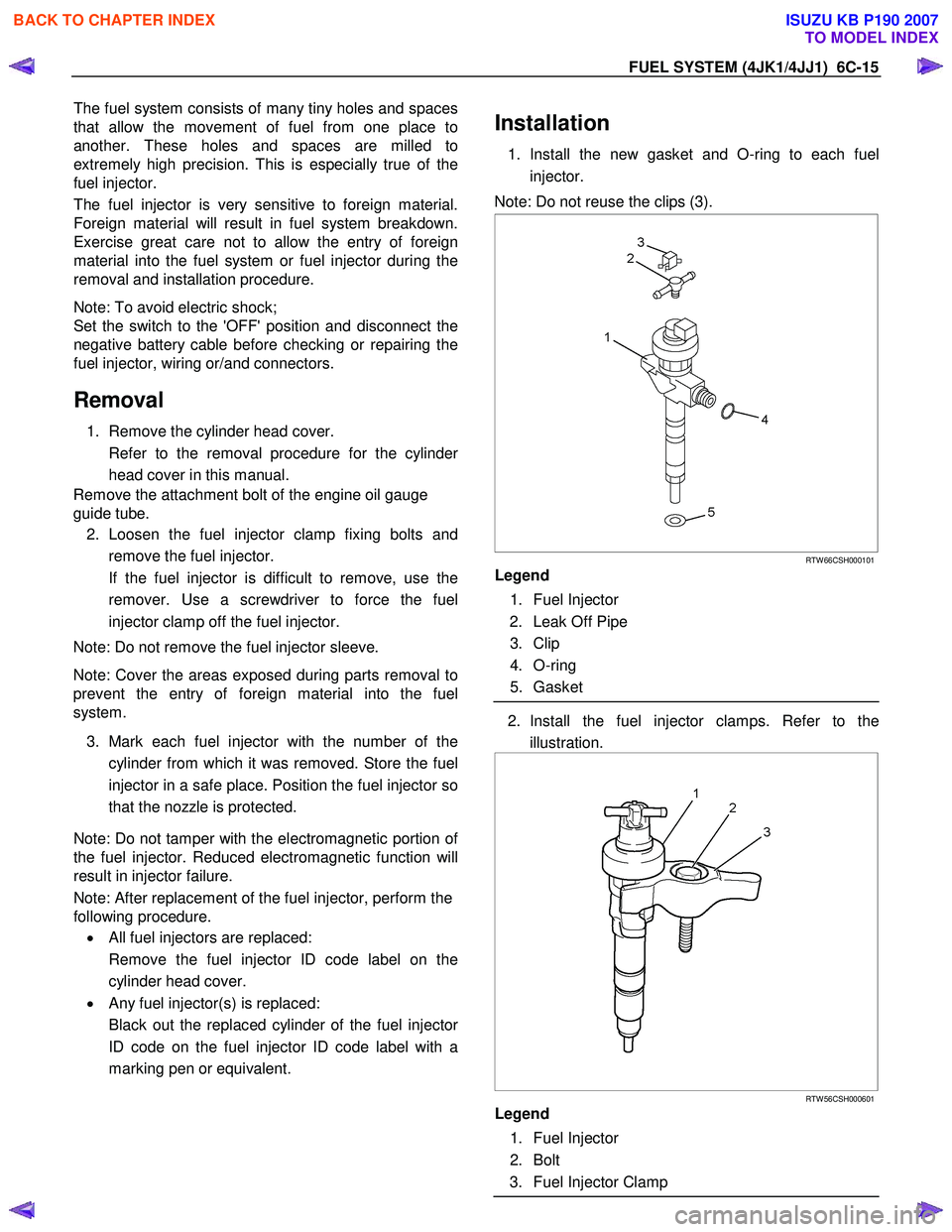
1. Install the new gasket and O-ring to each fuel
injector.
Note: Do not reuse the clips (3).
RTW 66CSH000101
Legend
1. Fuel Injector
2. Leak Off Pipe
3. Clip
4. O-ring
5. Gasket
2. Install the fuel injector clamps. Refer to the
illustration.
RTW 56CSH000601
Legend
1. Fuel Injector
2. Bolt
3. Fuel Injector Clamp
BACK TO CHAPTER INDEX
TO MODEL INDEX
ISUZU KB P190 2007
Page 1590 of 6020
6D-2 ENGINE ELECTRICAL (4JK1/4JJ1)
Charging System
Servicing Cautions
• Battery polarity is important. If the battery cables
are reversed, the generator diodes will be
destroyed.
• Do not remove the battery cables or the charging
circuit wiring when the engine is running.
• Confirm that the terminal wires are connected to
the proper terminals by checking the terminal
numbers (the number on the terminal wire and the
terminal must be the same).
• Disconnect the battery negative cable (-) before
inspecting the generator.
• Do not open or close the battery relay switch when
the engine is running.
• Disconnect the battery negative cable (-) when
using external equipment (Quick-Charge) to
charge the battery.
• W hen steam cleaning or washing the engine, do
not allow steam or water to come in direct contact
with the battery and other electrical system
components.
• Be sure to read the item on belt tension
adjustment before beginning the procedure.
Important Generator Components
and Function
• The generator used on 4JK1 engine cannot be
disassembled.
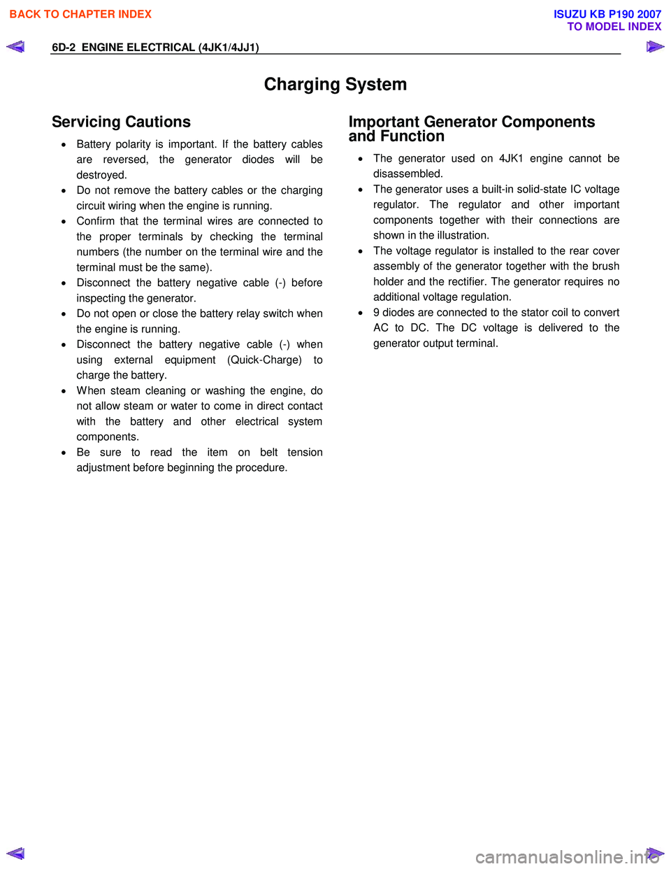
• The generator uses a built-in solid-state IC voltage
regulator. The regulator and other important
components together with their connections are
shown in the illustration.
• The voltage regulator is installed to the rear cove
r
assembly of the generator together with the brush
holder and the rectifier. The generator requires no
additional voltage regulation.
• 9 diodes are connected to the stator coil to convert
AC to DC. The DC voltage is delivered to the
generator output terminal.
BACK TO CHAPTER INDEX
TO MODEL INDEX
ISUZU KB P190 2007
Page 1594 of 6020
6D-6 ENGINE ELECTRICAL (4JK1/4JJ1)
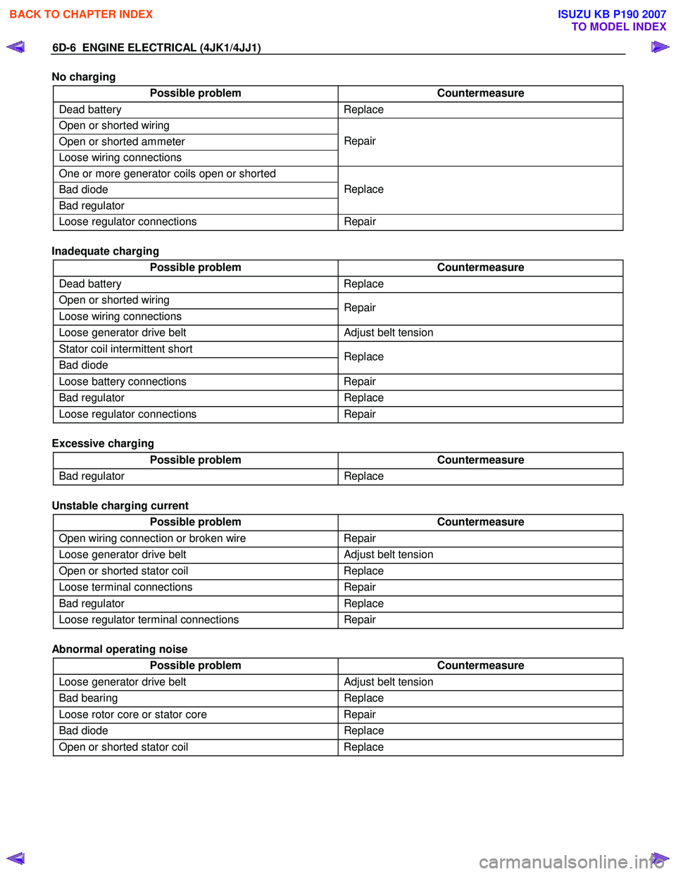
No charging
Possible problem Countermeasure
Dead battery Replace
Open or shorted wiring
Open or shorted ammeter
Loose wiring connections Repair
One or more generator coils open or shorted
Bad diode
Bad regulator Replace
Loose regulator connections
Repair
Inadequate charging
Possible problem Countermeasure
Dead battery Replace
Open or shorted wiring
Loose wiring connections Repair
Loose generator drive belt
Adjust belt tension
Stator coil intermittent short
Bad diode Replace
Loose battery connections
Repair
Bad regulator Replace
Loose regulator connections Repair
Excessive charging
Possible problem Countermeasure
Bad regulator Replace
Unstable charging current
Possible problem Countermeasure
Open wiring connection or broken wire Repair
Loose generator drive belt Adjust belt tension
Open or shorted stator coil Replace
Loose terminal connections Repair
Bad regulator Replace
Loose regulator terminal connections Repair
Abnormal operating noise
Possible problem Countermeasure
Loose generator drive belt Adjust belt tension
Bad bearing Replace
Loose rotor core or stator core Repair
Bad diode Replace
Open or shorted stator coil Replace
BACK TO CHAPTER INDEX
TO MODEL INDEX
ISUZU KB P190 2007
Page 1768 of 6020
ENGINE CONTROL SYSTEM (4JK1/4JJ1) 6E-151
DTC P0336 (Flash Code 15)
Circuit Description
The crankshaft position (CKP) sensor is located on the
left-hand of the cylinder block rear and it is behind the
starter motor. The sensor rotor is fixed on the
crankshaft. There are 56 notches spaced 6 ° apart and
a 30 ° section that is open span. This open span portion
allows for the detection of top dead center (TDC). The
ECM monitors both CKP sensor and camshaft position
(CMP) sensor signal pulses to ensure they correlate
with each other. If the ECM receives extra or missing
CKP sensor signal pulse, this DTC will set.
Condition for Running the DTC • DTC P0335 is not set.
• The battery voltage is more than 9 volts.
• The ignition switch is ON.
• The CKP sensor signal pulse is detected.
Condition for Setting the DTC • The ECM detects extra or missing CKP sensor signal pulses during engine rotations. Action Taken When the DTC Sets
• The ECM illuminates the MIL when the diagnostic runs and fails. Refer to DTC Type Definitions for
Action Taken When the DTC Sets - Type A.
• The ECM limits fuel injection quantity.
• The ECM inhibits pilot injection.
• The ECM inhibits cruise control.
Condition for Clearing the DTC • Refer to DTC Type Definitions for Condition for Clearing the MIL/ DTC - Type A.
Diagnostic Aids • If an intermittent condition is suspected, refer to Intermittent Conditions in this section.
• Electromagnetic interference in the CKP sensor circuits may set this DTC.
• An intermittent CKP sensor signal pulse may set this DTC.
• Ensure the sensor is tight and the sensor rotor teeth are not damaged.
Schematic Reference: Engine Controls Schematics
Connector End View Reference: Engine Controls
Connector End Views or ECM Connector End Views
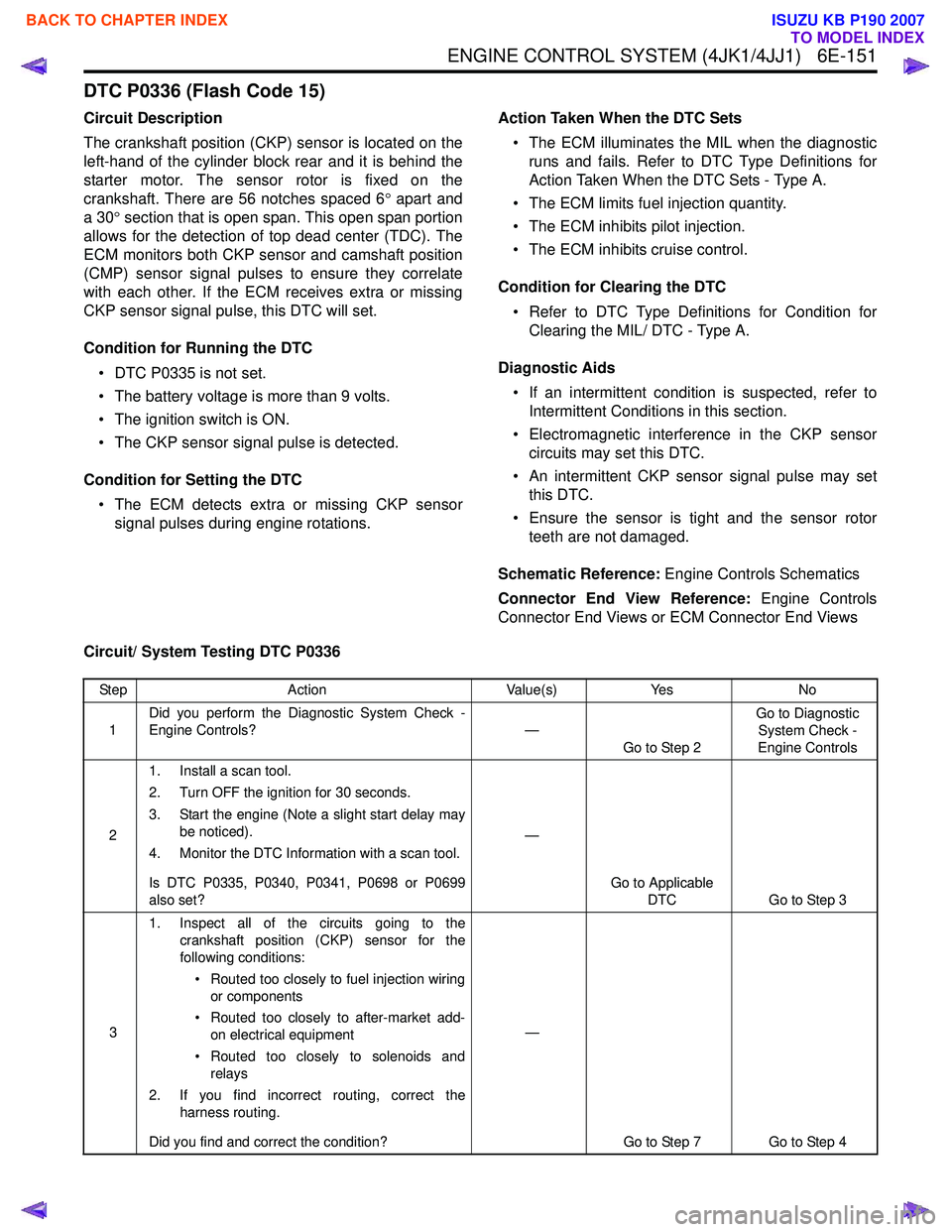
Circuit/ System Testing DTC P0336
Step Action Value(s)Yes No
1 Did you perform the Diagnostic System Check -
Engine Controls? —
Go to Step 2 Go to Diagnostic
System Check -
Engine Controls
2 1. Install a scan tool.
2. Turn OFF the ignition for 30 seconds.
3. Start the engine (Note a slight start delay may be noticed).
4. Monitor the DTC Information with a scan tool.
Is DTC P0335, P0340, P0341, P0698 or P0699
also set? —
Go to Applicable DTC Go to Step 3
3 1. Inspect all of the circuits going to the
crankshaft position (CKP) sensor for the
following conditions:
• Routed too closely to fuel injection wiring or components
• Routed too closely to after-market add- on electrical equipment
• Routed too closely to solenoids and relays
2. If you find incorrect routing, correct the harness routing.
Did you find and correct the condition? —
Go to Step 7 Go to Step 4
BACK TO CHAPTER INDEX
TO MODEL INDEX
ISUZU KB P190 2007