2007 ISUZU KB P190 lock
[x] Cancel search: lockPage 2264 of 6020
6E–94 ENGINE DRIVEABILITY AND EMISSIONS
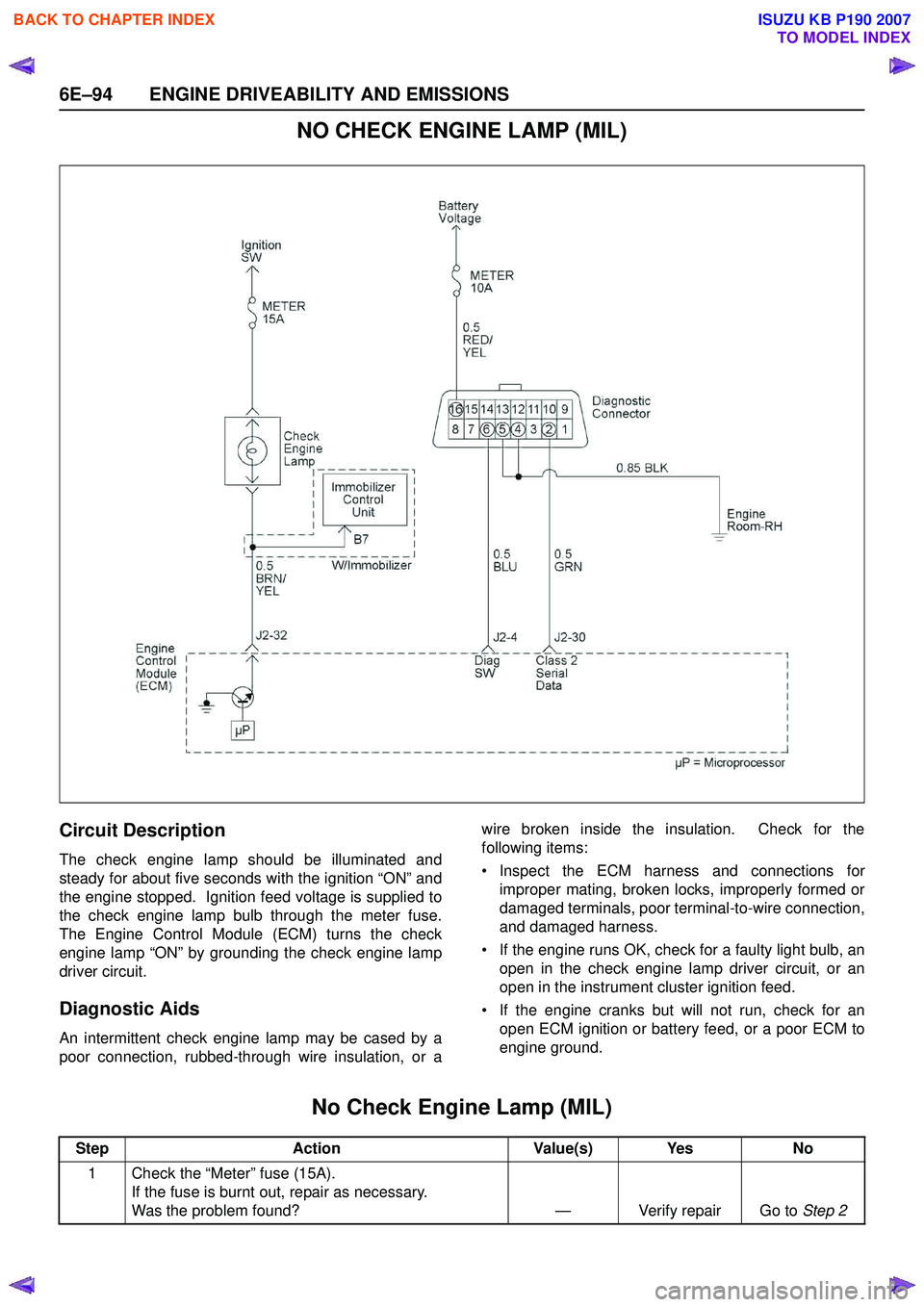
NO CHECK ENGINE LAMP (MIL)
Circuit Description
The check engine lamp should be illuminated and
steady for about five seconds with the ignition “ON” and
the engine stopped. Ignition feed voltage is supplied to
the check engine lamp bulb through the meter fuse.
The Engine Control Module (ECM) turns the check
engine lamp “ON” by grounding the check engine lamp
driver circuit.
Diagnostic Aids
An intermittent check engine lamp may be cased by a
poor connection, rubbed-through wire insulation, or a wire broken inside the insulation. Check for the
following items:
• Inspect the ECM harness and connections for improper mating, broken locks, improperly formed or
damaged terminals, poor terminal-to-wire connection,
and damaged harness.
• If the engine runs OK, check for a faulty light bulb, an open in the check engine lamp driver circuit, or an
open in the instrument cluster ignition feed.
• If the engine cranks but will not run, check for an open ECM ignition or battery feed, or a poor ECM to
engine ground.
No Check Engine Lamp (MIL)
Step Action Value(s) Yes No
1 Check the “Meter” fuse (15A). If the fuse is burnt out, repair as necessary.
Was the problem found? — Verify repair Go to Step 2
BACK TO CHAPTER INDEX
TO MODEL INDEX
ISUZU KB P190 2007
Page 2266 of 6020
6E–96 ENGINE DRIVEABILITY AND EMISSIONS
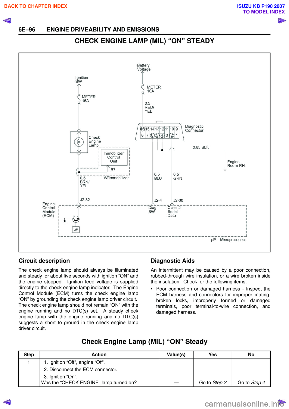
CHECK ENGINE LAMP (MIL) “ON” STEADY
Circuit description
The check engine lamp should always be illuminated
and steady for about five seconds with ignition “ON” and
the engine stopped. Ignition feed voltage is supplied
directly to the check engine lamp indicator. The Engine
Control Module (ECM) turns the check engine lamp
“ON” by grounding the check engine lamp driver circuit.
The check engine lamp should not remain “ON” with the
engine running and no DTC(s) set. A steady check
engine lamp with the engine running and no DTC(s)
suggests a short to ground in the check engine lamp
driver circuit.
Diagnostic Aids
An intermittent may be caused by a poor connection,
rubbed-through wire insulation, or a wire broken inside
the insulation. Check for the following items:
• Poor connection or damaged harness - Inspect the ECM harness and connectors for improper mating,
broken locks, improperly formed or damaged
terminals, poor terminal-to-wire connection, and
damaged harness.
Check Engine Lamp (MIL) “ON” Steady
Step Action Value(s) Yes No
1 1. Ignition “Off”, engine “Off”. 2. Disconnect the ECM connector.
3. Ignition “On”.
Was the “CHECK ENGINE” lamp turned on? — Go to Step 2Go to Step 4
BACK TO CHAPTER INDEX
TO MODEL INDEX
ISUZU KB P190 2007
Page 2273 of 6020
ENGINE DRIVEABILITY AND EMISSIONS 6E–103
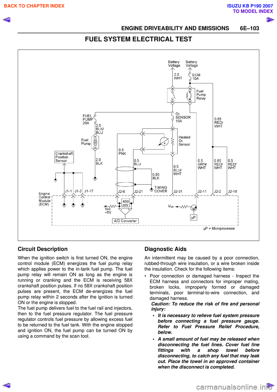
FUEL SYSTEM ELECTRICAL TEST
Circuit Description
When the ignition switch is first turned ON, the engine
control module (ECM) energizes the fuel pump relay
which applies power to the in-tank fuel pump. The fuel
pump relay will remain ON as long as the engine is
running or cranking and the ECM is receiving 58X
crankshaft position pulses. If no 58X crankshaft position
pulses are present, the ECM de-energizes the fuel
pump relay within 2 seconds after the ignition is turned
ON or the engine is stopped.
The fuel pump delivers fuel to the fuel rail and injectors,
then to the fuel pressure regulator. The fuel pressure
regulator controls fuel pressure by allowing excess fuel
to be returned to the fuel tank. With the engine stopped
and ignition ON, the fuel pump can be turned ON by
using a command by the scan tool.
Diagnostic Aids
An intermittent may be caused by a poor connection,
rubbed-through wire insulation, or a wire broken inside
the insulation. Check for the following items:
• Poor connection or damaged harness - Inspect the ECM harness and connectors for improper mating,
broken locks, improperly formed or damaged
terminals, poor terminal-to-wire connection, and
damaged harness. Caution: To reduce the risk of fire and personal
injury:
• It is necessary to relieve fuel system pressure before connecting a fuel pressure gauge.
Refer to Fuel Pressure Relief Procedure,
below.
• A small amount of fuel may be released when disconnecting the fuel lines. Cover fuel line
fittings with a shop towel before
disconnecting, to catch any fuel that may leak
out. Place the towel in an approved container
when the disconnect is completed.
BACK TO CHAPTER INDEX
TO MODEL INDEX
ISUZU KB P190 2007
Page 2281 of 6020
ENGINE DRIVEABILITY AND EMISSIONS 6E–111
10 Locate and repair the loss of vacuum to the fuelpressure regulator.
Is the action complete? — Verify repair —
11 Replace the fuel pressure regulator. Is the action complete? — Verify repair —
12 1. Run the fuel pump with the Scan Tool. 2. After pressure has built up, turn off the pump andclamp the supply hose shut with suitable locking
pliers.
Does the fuel pressure indicated by the fuel pressure
gauge remain constant? — Go to Step 13Go to Step 15
13 Visually inspect the fuel supply line and repair any leaks.
Was a problem found? — Verify repair Go to Step 14
14 Remove the fuel tank and inspect for leaky hose or in- tank fuel line.
Was a problem found? — Verify repair Go to Step 8
15 1. If the pliers are still clamped to the fuel supply hose, remove the locking pliers.
2. With suitable locking pliers, clamp the fuel return line to prevent fuel from returning to the fuel tank.
3. Run the fuel pump with the Scan Tool.
4. After pressure has built up, remove power to the pump.
Does the fuel pressure indicated by the fuel pressure
gauge remain constant? — Go to Step 11Go to Step 16
16 Locate and replace any leaking fuel injector(s). Is the action complete? — Verify repair —
17 Is the fuel pressure indicated by the fuel pressure gauge above the specified limit? 376 kPa
(55 psi) Go to Step 18Go to Step 21
18 1. Relieve the fuel pressure. Refer to the Fuel
Pressure Relief .
2. Disconnect the fuel return line from the fuel rail.
3. Attach a length of flexible hose to the fuel rail return outlet passage.
4. Place the open end of the flexible hose into an approved gasoline container.
5. Run the fuel pump with the Scan Tool.
6. Observe the fuel pressure indicated by the fuel pressure gauge with the fuel pump running.
Is the fuel pressure within the specified limits? 290-376 kPa
(42-55 psi) Go to Step 19Go to Step 20
19 Locate and correct the restriction in the fuel return line.
Is the action complete? — Verify repair —
20 Visually and physically inspect the fuel rail outlet passages for a restriction.
Was a restriction found? — Verify repair Go to Step 11
21 Is the fuel pressure indicated by the fuel pressure gauge above the specified value? 0 kPa (0 psi) Go to Step 22Go to Step 23
Step
Action Value(s) Yes No
BACK TO CHAPTER INDEX
TO MODEL INDEX
ISUZU KB P190 2007
Page 2290 of 6020
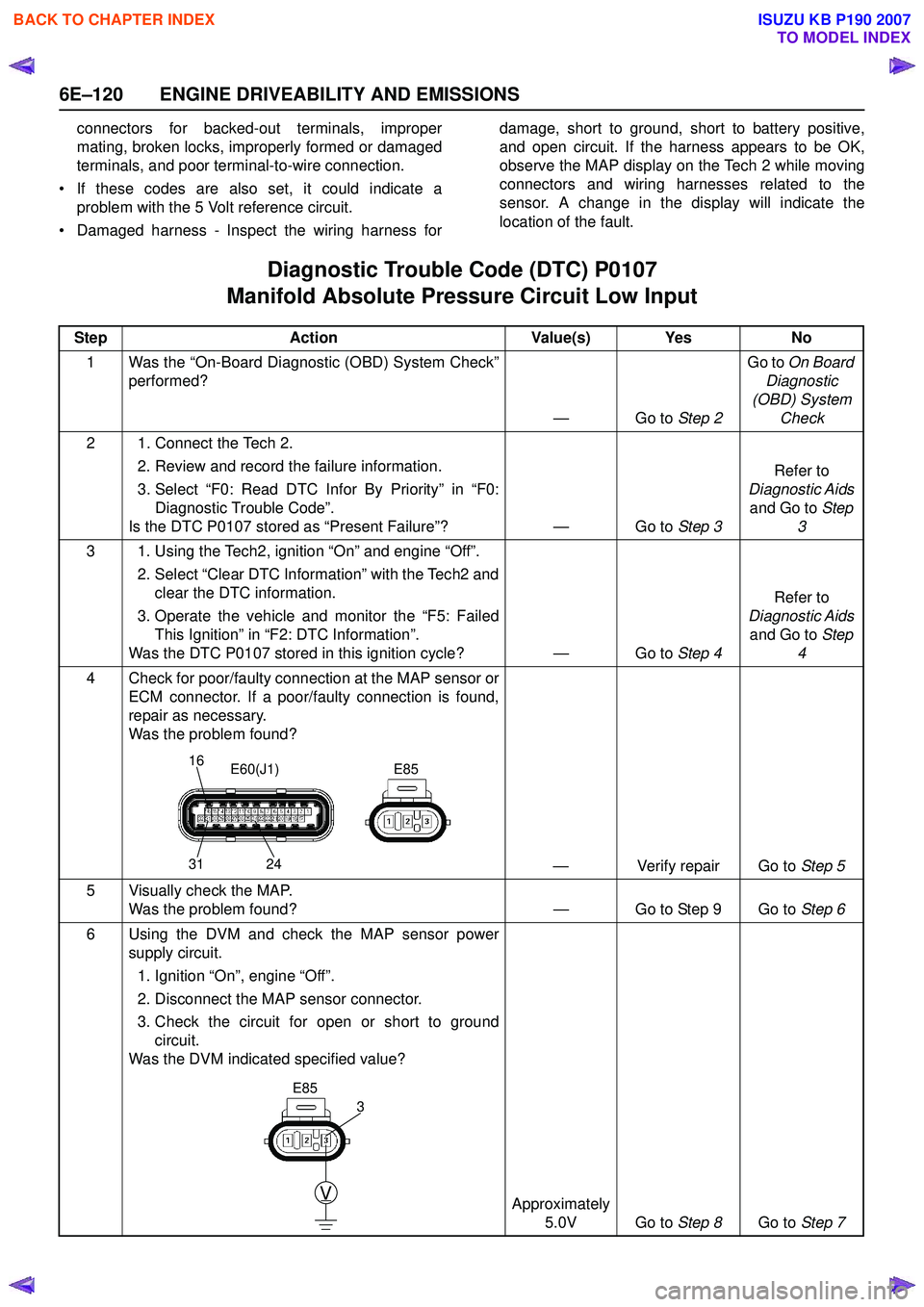
6E–120 ENGINE DRIVEABILITY AND EMISSIONS
connectors for backed-out terminals, improper
mating, broken locks, improperly formed or damaged
terminals, and poor terminal-to-wire connection.
• If these codes are also set, it could indicate a problem with the 5 Volt reference circuit.
• Damaged harness - Inspect the wiring harness for damage, short to ground, short to battery positive,
and open circuit. If the harness appears to be OK,
observe the MAP display on the Tech 2 while moving
connectors and wiring harnesses related to the
sensor. A change in the display will indicate the
location of the fault.
Diagnostic Trouble Code (DTC) P0107
Manifold Absolute Pressure Circuit Low Input
Step Action Value(s) Yes No
1 Was the “On-Board Diagnostic (OBD) System Check” performed?
—Go to Step 2Go to
On Board
Diagnostic
(OBD) System Check
2 1. Connect the Tech 2. 2. Review and record the failure information.
3. Select “F0: Read DTC Infor By Priority” in “F0: Diagnostic Trouble Code”.
Is the DTC P0107 stored as “Present Failure”? — Go to Step 3Refer to
Diagnostic Aids and Go to Step
3
3 1. Using the Tech2, ignition “On” and engine “Off”. 2. Select “Clear DTC Information” with the Tech2 andclear the DTC information.
3. Operate the vehicle and monitor the “F5: Failed This Ignition” in “F2: DTC Information”.
Was the DTC P0107 stored in this ignition cycle? — Go to Step 4Refer to
Diagnostic Aids and Go to Step
4
4 Check for poor/faulty connection at the MAP sensor or ECM connector. If a poor/faulty connection is found,
repair as necessary.
Was the problem found?
— Verify repair Go to Step 5
5 Visually check the MAP. Was the problem found? — Go to Step 9 Go to Step 6
6 Using the DVM and check the MAP sensor power supply circuit.
1. Ignition “On”, engine “Off”.
2. Disconnect the MAP sensor connector.
3. Check the circuit for open or short to ground circuit.
Was the DVM indicated specified value?
Approximately 5.0V Go to Step 8Go to Step 7
16
31 24E85
E60(J1)
V
E85
3
BACK TO CHAPTER INDEX
TO MODEL INDEX
ISUZU KB P190 2007
Page 2294 of 6020
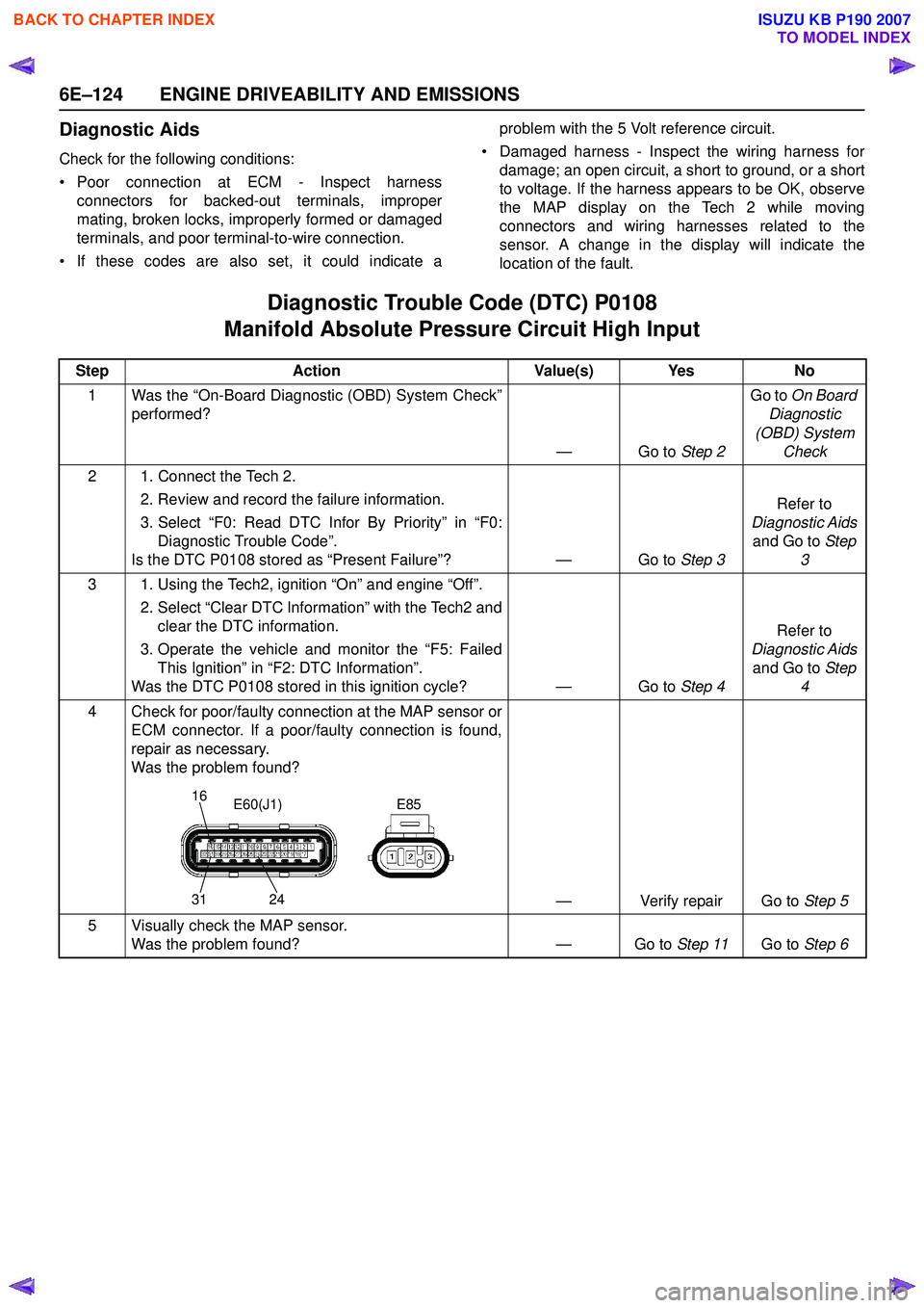
6E–124 ENGINE DRIVEABILITY AND EMISSIONS
Diagnostic Aids
Check for the following conditions:
• Poor connection at ECM - Inspect harness connectors for backed-out terminals, improper
mating, broken locks, improperly formed or damaged
terminals, and poor terminal-to-wire connection.
• If these codes are also set, it could indicate a problem with the 5 Volt reference circuit.
• Damaged harness - Inspect the wiring harness for damage; an open circuit, a short to ground, or a short
to voltage. If the harness appears to be OK, observe
the MAP display on the Tech 2 while moving
connectors and wiring harnesses related to the
sensor. A change in the display will indicate the
location of the fault.
Diagnostic Trouble Code (DTC) P0108
Manifold Absolute Pressure Circuit High Input
Step Action Value(s) Yes No
1 Was the “On-Board Diagnostic (OBD) System Check” performed?
—Go to Step 2Go to
On Board
Diagnostic
(OBD) System Check
2 1. Connect the Tech 2. 2. Review and record the failure information.
3. Select “F0: Read DTC Infor By Priority” in “F0: Diagnostic Trouble Code”.
Is the DTC P0108 stored as “Present Failure”? — Go to Step 3Refer to
Diagnostic Aids and Go to Step
3
3 1. Using the Tech2, ignition “On” and engine “Off”. 2. Select “Clear DTC Information” with the Tech2 andclear the DTC information.
3. Operate the vehicle and monitor the “F5: Failed This Ignition” in “F2: DTC Information”.
Was the DTC P0108 stored in this ignition cycle? — Go to Step 4Refer to
Diagnostic Aids and Go to Step
4
4 Check for poor/faulty connection at the MAP sensor or ECM connector. If a poor/faulty connection is found,
repair as necessary.
Was the problem found?
— Verify repair Go to Step 5
5 Visually check the MAP sensor. Was the problem found? — Go to Step 11Go to Step 6
16
31 24E85
E60(J1)
BACK TO CHAPTER INDEX
TO MODEL INDEX
ISUZU KB P190 2007
Page 2297 of 6020
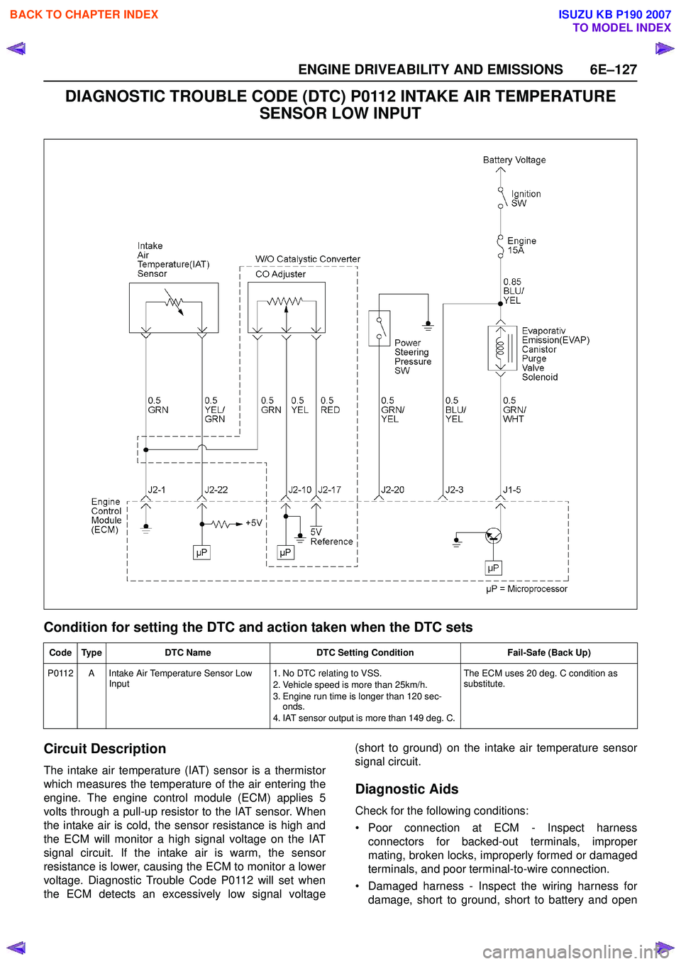
ENGINE DRIVEABILITY AND EMISSIONS 6E–127
DIAGNOSTIC TROUBLE CODE (DTC) P0112 INTAKE AIR TEMPERATURE SENSOR LOW INPUT
Condition for setting the DTC and action taken when the DTC sets
Circuit Description
The intake air temperature (IAT) sensor is a thermistor
which measures the temperature of the air entering the
engine. The engine control module (ECM) applies 5
volts through a pull-up resistor to the IAT sensor. When
the intake air is cold, the sensor resistance is high and
the ECM will monitor a high signal voltage on the IAT
signal circuit. If the intake air is warm, the sensor
resistance is lower, causing the ECM to monitor a lower
voltage. Diagnostic Trouble Code P0112 will set when
the ECM detects an excessively low signal voltage (short to ground) on the intake air temperature sensor
signal circuit.
Diagnostic Aids
Check for the following conditions:
• Poor connection at ECM - Inspect harness connectors for backed-out terminals, improper
mating, broken locks, improperly formed or damaged
terminals, and poor terminal-to-wire connection.
• Damaged harness - Inspect the wiring harness for damage, short to ground, short to battery and open
Code Type DTC Name DTC Setting Condition Fail-Safe (Back Up)
P0112 A Intake Air Temperature Sensor Low Input 1. No DTC relating to VSS.
2. Vehicle speed is more than 25km/h.
3. Engine run time is longer than 120 sec- onds.
4. IAT sensor output is more than 149 deg. C. The ECM uses 20 deg. C condition as
substitute.
BACK TO CHAPTER INDEX
TO MODEL INDEX
ISUZU KB P190 2007
Page 2301 of 6020
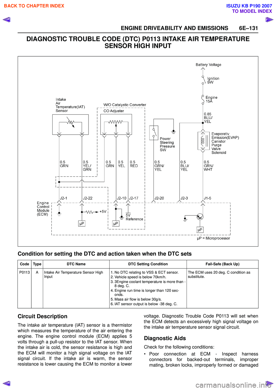
ENGINE DRIVEABILITY AND EMISSIONS 6E–131
DIAGNOSTIC TROUBLE CODE (DTC) P0113 INTAKE AIR TEMPERATURE SENSOR HIGH INPUT
Condition for setting the DTC and action taken when the DTC sets
Circuit Description
The intake air temperature (IAT) sensor is a thermistor
which measures the temperature of the air entering the
engine. The engine control module (ECM) applies 5
volts through a pull-up resistor to the IAT sensor. When
the intake air is cold, the sensor resistance is high and
the ECM will monitor a high signal voltage on the IAT
signal circuit. If the intake air is warm, the sensor
resistance is lower causing the ECM to monitor a lower voltage. Diagnostic Trouble Code P0113 will set when
the ECM detects an excessively high signal voltage on
the intake air temperature sensor signal circuit.
Diagnostic Aids
Check for the following conditions:
• Poor connection at ECM - Inspect harness connectors for backed-out terminals, improper
mating, broken locks, improperly formed or damaged
Code Type DTC Name DTC Setting Condition Fail-Safe (Back Up)
P0113 A Intake Air Temperature Sensor High Input 1. No DTC relating to VSS & ECT sensor.
2. Vehicle speed is below 70km/h.
3. 3Engine coolant temperature is more than - 8 deg. C.
4. Engine run time is longer than 120 sec- onds.
5. Mass air flow is below 30g/s.
6. IAT sensor output is below -38 deg. C. The ECM uses 20 deg. C condition as
substitute.
BACK TO CHAPTER INDEX
TO MODEL INDEX
ISUZU KB P190 2007