2007 ISUZU KB P190 lock
[x] Cancel search: lockPage 2127 of 6020
ENGINE FUEL (C24SE) 6C-9
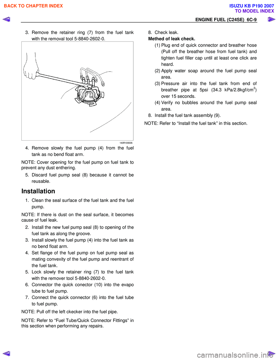
3. Remove the retainer ring (7) from the fuel tank
with the removal tool 5-8840-2602-0.
140R100035
4. Remove slowly the fuel pump (4) from the fuel
tank as no bend float arm.
NOTE: Cover opening for the fuel pump on fuel tank to
prevent any dust enthering.
5. Discard fuel pump seal (8) because it cannot be
reusable.
Installation
1. Clean the seal surface of the fuel tank and the fuel pump.
NOTE: If there is dust on the seal surface, it becomes
cause of fuel leak.
2. Install the new fuel pump seal (8) to opening of the fuel tank as along the groove.
3. Install slowly the fuel pump (4) into the fuel tank as no bend float arm.
4. Set flange of the fuel pump on fuel pump seal as
mating convexity of the fuel pump and reentrant o
f
the fuel tank.
5. Lock slowly the retainer ring (7) to the fuel tank
with the remover tool 5-8840-2602-0.
6. Connector the quick conector (10) into the evapo tube to fuel pump.
7. Connect the quick connector (6) into the fuel tube
to fuel pump.
NOTE: Pull off the left ckecker into the fuel pipe.
NOTE: Refer to “Fuel Tube/Quick Connector Fittings” in
this section when performing any repairs.
8. Check leak.
Methed of leak check.
(1) Plug end of quick connector and breather hose
(Pull off the breather hose from fuel tank) and
tighten fuel filler cap until at least one click are
heard.
(2)
Apply water soap around the fuel pump seal
area.
(3) Pressure air into the fuel tank from end o
f
breather pipe at 5psi (34.3 kPa/2.8kgf/cm2)
over 15 seconds.
(4) Verify no bubbles around the fuel pump seal
area.
8. Install the fuel tank assembly (9).
NOTE: Refer to “Install the fuel tank” in this section.
BACK TO CHAPTER INDEX
TO MODEL INDEX
ISUZU KB P190 2007
Page 2129 of 6020
ENGINE FUEL (C24SE) 6C-11
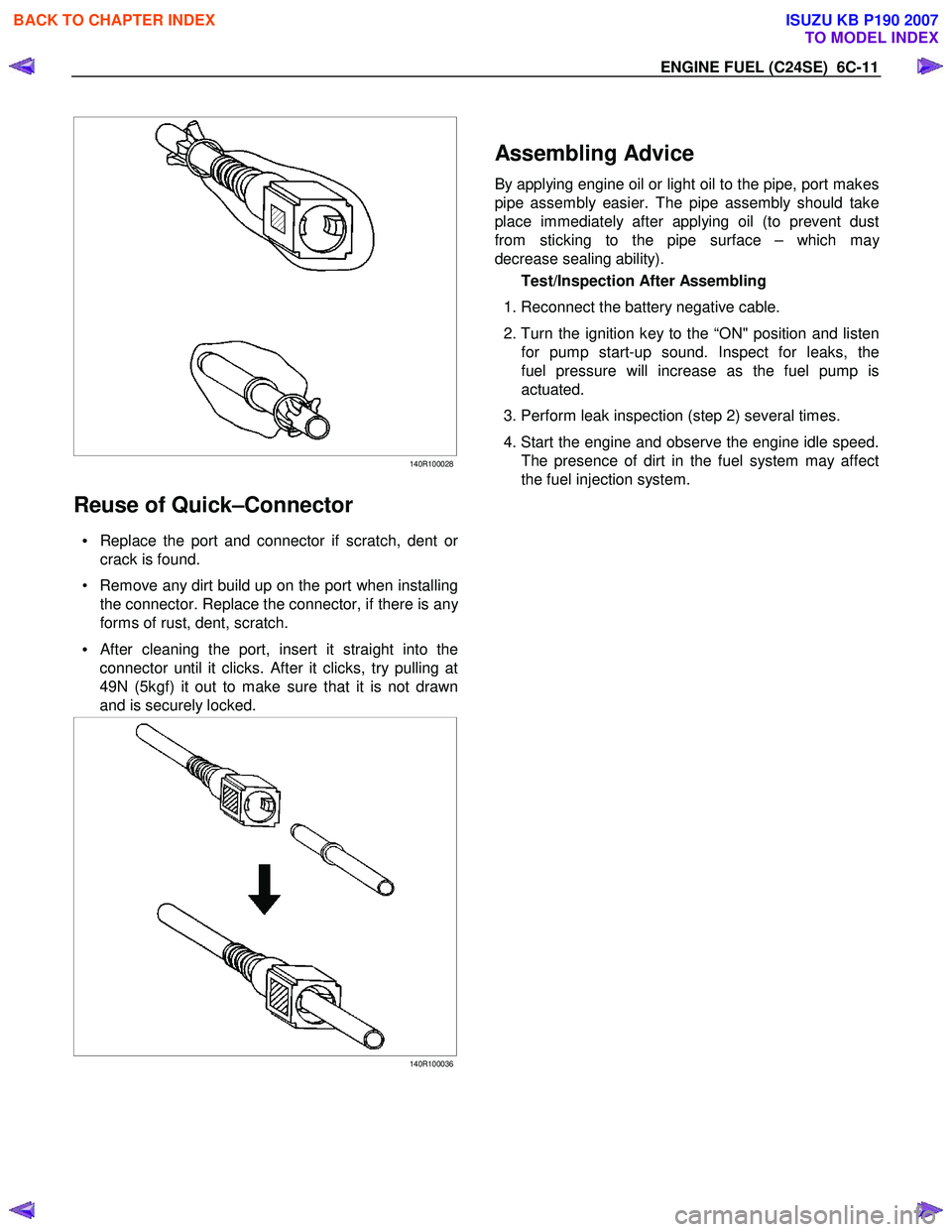
140R100028
Reuse of Quick–Connector
• Replace the port and connector if scratch, dent or
crack is found.
• Remove any dirt build up on the port when installing the connector. Replace the connector, if there is an
y
forms of rust, dent, scratch.
•
After cleaning the port, insert it straight into the
connector until it clicks. After it clicks, try pulling at
49N (5kgf) it out to make sure that it is not drawn
and is securely locked.
140R100036
Assembling Advice
By applying engine oil or light oil to the pipe, port makes
pipe assembly easier. The pipe assembly should take
place immediately after applying oil (to prevent dust
from sticking to the pipe surface – which ma
y
decrease sealing ability).
Test/Inspection After Assembling
1. Reconnect the battery negative cable.
2. Turn the ignition key to the “ON" position and listen
for pump start-up sound. Inspect for leaks, the
fuel pressure will increase as the fuel pump is
actuated.
3. Perform leak inspection (step 2) several times.
4. Start the engine and observe the engine idle speed.
The presence of dirt in the fuel system may affect
the fuel injection system.
BACK TO CHAPTER INDEX
TO MODEL INDEX
ISUZU KB P190 2007
Page 2139 of 6020
6D1-2 ENGINE ELECTRICAL
Battery
General Description
There are six battery fluid caps on top of the battery.
These are covered by a paper label.
The battery is completely sealed except for the six small vent
holes on the side. These vent holes permit the escape of small
amounts of gas generated by the battery.
This type of battery has the following advantages over
conventional batteries:
1. There is no need to add water during the entire service life
of the battery.
2. The battery protects itself against overcharging.
The battery will refuse to accept an extensive charge.
(A conventional battery will accept an excessive charge, resulting in gassing and loss of battery fluid.)
3. The battery is much less vulnerable to self discharge than a conventional type battery.
Service Precaution
CAUTION:
Always use the correct fastener in the proper location.
When you replace a fastener, use ONLY the exact part
number for that application. ISUZU will call out those
fasteners that require a replacement after removal. ISUZU
will also call out the fasteners that require thread lockers
or thread sealant. UNLESS OTHERWISE SPECIFIED, do
not use supplemental coatings (Paints, greases, or other
corrosion inhibitors) on threaded fasteners or fastener
joint interfaces. Generally, such coatings adversely affect
the fastener torque and the joint clamping force, and may
damage the fastener. When you install fasteners, use the
correct tightening sequence and specifications. Following
these instructions can help you avoid damage to parts
and systems.
BACK TO CHAPTER INDEX
TO MODEL INDEX
ISUZU KB P190 2007
Page 2145 of 6020
6D2-2 IGNITION SYSTEM
General Description
Ignition is done by the Ignition Module that fires.
Since the cylinder on exhaust stroke requires less energy to
fire its spark plug, energy from the ignition coils can be utilized
to fire the mating cylinder on compression stroke.
A notch in the timing disc on the crankshaft activates the crank
angle sensor which then sends information such as firing order
and starting timing of ignition coil to the ECM.
By receiving signals such as crank position, engine speed,
water temperature and Manifold Absolute Pressure (MAP), the
ECM controls the ignition timing.
Service Precaution
CAUTION:
Always use the correct fastener in the proper location.
When you replace a fastener, use ONLY the exact part
number for that application. ISUZU will call out those
fasteners that require a replacement after removal. ISUZU
will also call out the fasteners that require thread lockers
or thread sealant. UNLESS OTHERWISE SPECIFIED, do
not use supplemental coatings (Paints, greases, or other
corrosion inhibitors) on threaded fasteners or fastener
joint interfaces. Generally, such coatings adversely affect
the fastener torque and the joint clamping force, and may
damage the fastener. When you install fasteners, use the
correct tightening sequence and specifications. Following
these instructions can help you avoid damage to parts
and systems.
Diagnosis
Refer to Section Drivability and Emissions for the diagnosis to
electronic ignition system (El system).
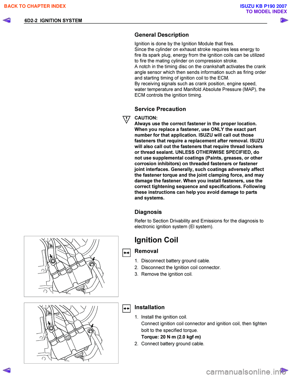
Ignition Coil
Removal
1. Disconnect battery ground cable.
2. Disconnect the Ignition coil connector.
3. Remove the ignition coil.
Installation
1. Install the ignition coil.
Connect ignition coil connector and ignition coil, then tighten bolt to the specified torque.
Torque: 20 N ⋅m (2.0 kgf ⋅m)
2. Connect battery ground cable.
BACK TO CHAPTER INDEX
TO MODEL INDEX
ISUZU KB P190 2007
Page 2147 of 6020
6D2-4 IGNITION SYSTEM
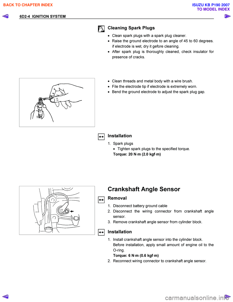
Cleaning Spark Plugs
• Clean spark plugs with a spark plug cleaner.
• Raise the ground electrode to an angle of 45 to 60 degrees.
if electrode is wet, dry it gefore cleaning.
•
After spark plug is thoroughly cleaned, check insulator for
presence of cracks.
• Clean threads and metal body with a wire brush.
• File the electrode tip if electrode is extremely worn.
• Bend the ground electrode to adjust the spark plug gap.
Installation
1. Spark plugs
• Tighten spark plugs to the specified torque.
Torque: 20 N ⋅m (2.0 kgf ⋅m)
Crankshaft Angle Sensor
Removal
1. Disconnect battery ground cable
2. Disconnect the wiring connector from crankshaft angle sensor.
3. Remove crankshaft angle sensor from cylinder block.
Installation
1. Install crankshaft angle sensor into the cylinder block.
Before installation, apply small amount of engine oil to the O-ring.
Torque: 6 N ⋅m (0.6 kgf ⋅m)
2. Reconnect wiring connector to crankshaft angle sensor.
BACK TO CHAPTER INDEX
TO MODEL INDEX
ISUZU KB P190 2007
Page 2150 of 6020
6D3-2 STARTING AND CHARGING SYSTEM
Starting System
General Description
Cranking Circuit
The cranking system consists of a battery, starter, starter
switch, starter relay, etc. These main components are
connected.
Starter
The cranking system employs a magnetic type reduction
starter in which the motor shaft is also used as a pinion shaft.
W hen the starter switch is turned on, the contacts of magnetic
switch are closed, and the armature rotates. At the same time,
the plunger is attracted, and the pinion is pushed forward by
the shift lever to mesh with the ring gear.
Then, the ring gear runs to start the engine. W hen the engine
starts and the starter switch is turned off, the plunger returns,
the pinion is disengaged from the ring gear, and the armature
stops rotation. W hen the engine speed is higher than the
pinion, the pinion idles, so that the armature is not driven.
Service Precaution
CAUTION:
Always use the correct fastener in the proper location.
When you replace a fastener, use ONLY the exact part
number for that application. ISUZU will call out those
fasteners that require a replacement after removal. ISUZU
will also call out the fasteners that require thread lockers
or thread sealant. UNLESS OTHERWISE SPECIFIED, do
not use supplemental coatings (Paints, greases, or other
corrosion inhibitors) on threaded fasteners or fastener
joint interfaces. Generally, such coatings adversely affect
the fastener torque and the joint clamping force, and may
damage the fastener. When you install fasteners, use the
correct tightening sequence and specifications. Following
these instructions can help you avoid damage to parts
and systems.
Diagnosis
Condition Possible cause Correction
Starter does not run Charging failure Repair charging system
Battery Failure Replace Battery
Terminal connection failure Repair or replace terminal connector
and/or wiring harness
Starter switch failure Repair or replace starter switch
Starter failure Repair or replace starter
BACK TO CHAPTER INDEX
TO MODEL INDEX
ISUZU KB P190 2007
Page 2154 of 6020
6D3-6 STARTING AND CHARGING SYSTEM
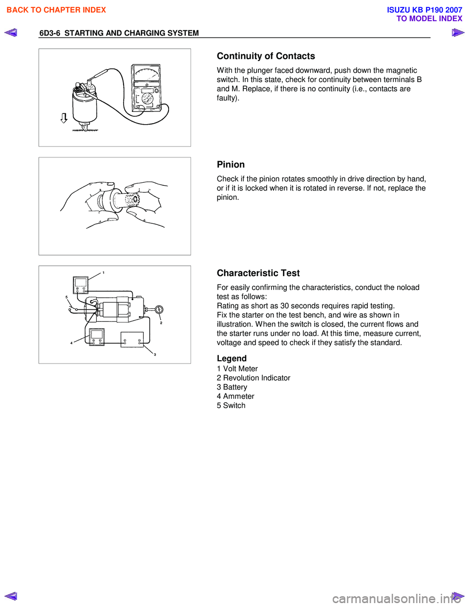
Continuity of Contacts
W ith the plunger faced downward, push down the magnetic
switch. In this state, check for continuity between terminals B
and M. Replace, if there is no continuity (i.e., contacts are
faulty).
Pinion
Check if the pinion rotates smoothly in drive direction by hand,
or if it is locked when it is rotated in reverse. If not, replace the
pinion.
Characteristic Test
For easily confirming the characteristics, conduct the noload
test as follows:
Rating as short as 30 seconds requires rapid testing.
Fix the starter on the test bench, and wire as shown in
illustration. W hen the switch is closed, the current flows and
the starter runs under no load. At this time, measure current,
voltage and speed to check if they satisfy the standard.
Legend
1 Volt Meter
2 Revolution Indicator
3 Battery
4 Ammeter
5 Switch
BACK TO CHAPTER INDEX
TO MODEL INDEX
ISUZU KB P190 2007
Page 2156 of 6020
6D3-8 STARTING AND CHARGING SYSTEM
General On-Vehicle Inspection
The operating condition of charging system is indicated by the
charge warning lamp. The warning lamp comes on when the
starter switch is turned to "ON" position. The charging system
operates normally if the lamp goes off when the engine starts.
If the warning lamp shows abnormality or if undercharged or
overcharged battery condition is suspected, perform diagnosis
by checking the charging system as follows:
1. Check visually the belt and wiring connector.
2. W ith the engine stopped, turn the stator switch to "ON" position and observe the warning lamp.
If lamp does not come on:
Disconnect wiring connector from generator, and ground the terminal "L" on connector side.
If lamp comes on:
Repair or replace the generator.
Generator
Removal
1. Disconnect battery ground cable.
2. Move drive belt tensioner to loose side using wrench then remove drive belt.
3. Disconnect terminal "B" wiring connector and connector.
4. Remove generator assembly.
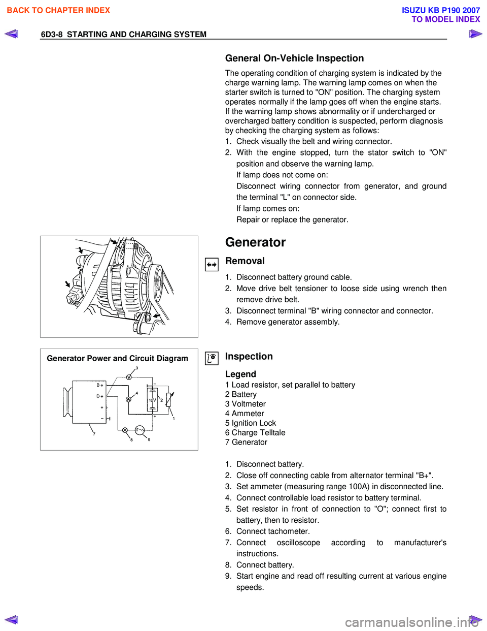
Generator Power and Circuit Diagram
Inspection
Legend
1 Load resistor, set parallel to battery
2 Battery
3 Voltmeter
4 Ammeter
5 Ignition Lock
6 Charge Telltale
7 Generator
1. Disconnect battery.
2. Close off connecting cable from alternator terminal "B+".
3. Set ammeter (measuring range 100A) in disconnected line.
4. Connect controllable load resistor to battery terminal.
5. Set resistor in front of connection to "O"; connect first to battery, then to resistor.
6. Connect tachometer.
7. Connect oscilloscope according to manufacturer's instructions.
8. Connect battery.
9. Start engine and read off resulting current at various engine speeds.
BACK TO CHAPTER INDEX
TO MODEL INDEX
ISUZU KB P190 2007