2007 ISUZU KB P190 check oil
[x] Cancel search: check oilPage 3539 of 6020
Engine Management – V6 – Service Operations Page 6C1-3–15
Test
To prevent component and damage use
connector test adaptor kit J 35616-A.
Resistance Check
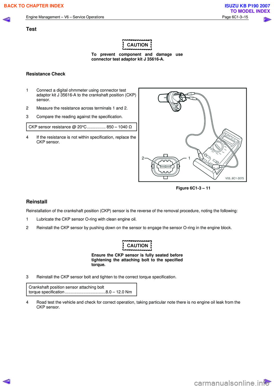
1 Connect a digital ohmmeter using connector test adaptor kit J 35616-A to the crankshaft position (CKP)
sensor.
2 Measure the resistance across terminals 1 and 2.
3 Compare the reading against the specification.
CKP sensor resistance @ 20°C ................ 850 – 1040 Ω
4 If the resistance is not within specification, replace the
CKP sensor.
Figure 6C1-3 – 11
Reinstall
Reinstallation of the crankshaft position (CKP) sensor is the reverse of the removal procedure, noting the following:
1 Lubricate the CKP sensor O-ring with clean engine oil.
2 Reinstall the CKP sensor by pushing down on the sensor to engage the sensor O-ring in the engine block.
Ensure the CKP sensor is fully seated before
tightening the attaching bolt to the specified
torque.
3 Reinstall the CKP sensor bolt and tighten to the correct torque specification. Crankshaft position sensor attaching bolt
torque specification ...................................8.0 – 12.0 Nm
4 Road test the vehicle and check for correct operation, taking particular note there is no engine oil leak from the CKP sensor.
BACK TO CHAPTER INDEX
TO MODEL INDEX
ISUZU KB P190 2007
Page 3546 of 6020
Engine Management – V6 – Service Operations Page 6C1-3–22
3 Road test the vehicle and check for correct operation.
2.9 Engine Oil Level and Temperature
Sensor
To avoid personal injury, take care when
draining the engine oil or removing the engine
oil level and temperature sensor whilst the
engine is hot. Allow the engine to cool before
performing this procedure.
Remove
1 Turn the ignition switch off.
2 Raise the front and rear of the vehicle and support on safety stands, refer to 0A General Information for location of the jacking points.
3 Drain the engine oil, refer to 6A1 Engine Mechanical – V6.
Clean the area around the engine oil level
and temperature sensor (1) before removal to
avoid debris from entering the engine.
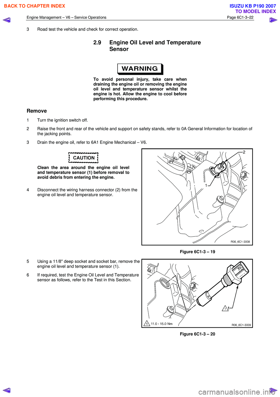
4 Disconnect the wiring harness connector (2) from the engine oil level and temperature sensor.
Figure 6C1-3 – 19
5 Using a 11/8" deep socket and socket bar, remove the engine oil level and temperature sensor (1).
6 If required, test the Engine Oil Level and Temperature sensor as follows, refer to the Test in this Section.
Figure 6C1-3 – 20
BACK TO CHAPTER INDEX
TO MODEL INDEX
ISUZU KB P190 2007
Page 3547 of 6020
Engine Management – V6 – Service Operations Page 6C1-3–23
Test
Engine Oil Level Sensor Check
1 W ith the aid of an assistant, perform the following:
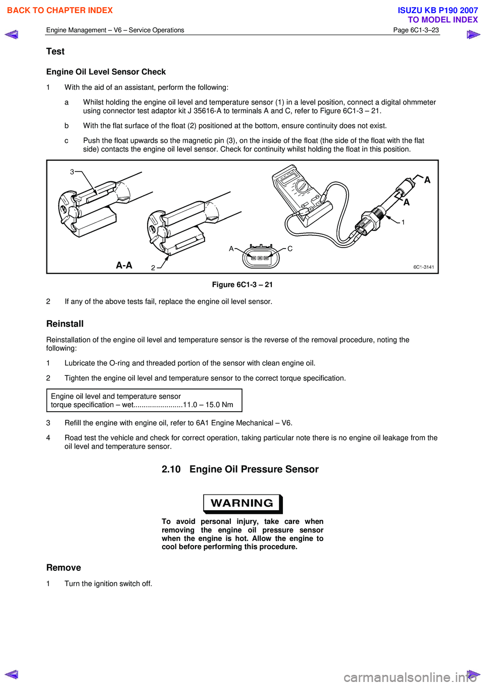
a W hilst holding the engine oil level and temperature sensor (1) in a level position, connect a digital ohmmeter using connector test adaptor kit J 35616-A to terminals A and C, refer to Figure 6C1-3 – 21.
b W ith the flat surface of the float (2) positioned at the bottom, ensure continuity does not exist.
c Push the float upwards so the magnetic pin (3), on the inside of the float (the side of the float with the flat side) contacts the engine oil level sensor. Check for continuity whilst holding the float in this position.
Figure 6C1-3 – 21
2 If any of the above tests fail, replace the engine oil level sensor.
Reinstall
Reinstallation of the engine oil level and temperature sensor is the reverse of the removal procedure, noting the
following:
1 Lubricate the O-ring and threaded portion of the sensor with clean engine oil.
2 Tighten the engine oil level and temperature sensor to the correct torque specification.
Engine oil level and temperature sensor
torque specification – wet........................11.0 – 15.0 Nm
3 Refill the engine with engine oil, refer to 6A1 Engine Mechanical – V6.
4 Road test the vehicle and check for correct operation, taking particular note there is no engine oil leakage from the oil level and temperature sensor.
2.10 Engine Oil Pressure Sensor
To avoid personal injury, take care when
removing the engine oil pressure sensor
when the engine is hot. Allow the engine to
cool before performing this procedure.
Remove
1 Turn the ignition switch off.
BACK TO CHAPTER INDEX
TO MODEL INDEX
ISUZU KB P190 2007
Page 3548 of 6020
Engine Management – V6 – Service Operations Page 6C1-3–24
Clean the area around the engine oil pressure
sensor before removal to avoid debris from
entering the engine.
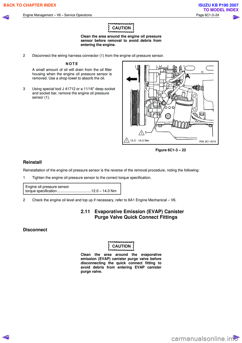
2 Disconnect the wiring harness connector (1) from the engine oil pressure sensor. NOTE
A small amount of oil will drain from the oil filter
housing when the engine oil pressure sensor is
removed. Use a shop towel to absorb the oil.
3 Using special tool J 41712 or a 11/16" deep socket and socket bar, remove the engine oil pressure
sensor (1).
Figure 6C1-3 – 22
Reinstall
Reinstallation of the engine oil pressure sensor is the reverse of the removal procedure, noting the following:
1 Tighten the engine oil pressure sensor to the correct torque specification.
Engine oil pressure sensor
torque specification .................................12.0 – 14.0 Nm
2 Check the engine oil level and top up if necessary, refer to 6A1 Engine Mechanical – V6.
2.11 Evaporative Emission (EVAP) Canister Purge Valve Quick Connect Fittings
Disconnect
Clean the area around the evaporative
emission (EVAP) canister purge valve before
disconnecting the quick connect fitting to
avoid debris from entering EVAP canister
purge valve.
BACK TO CHAPTER INDEX
TO MODEL INDEX
ISUZU KB P190 2007
Page 3557 of 6020
Engine Management – V6 – Service Operations Page 6C1-3–33
Reinstall
Reinstallation of the fuel injector wiring harness assembly is the reverse of the removal procedure, noting the following:
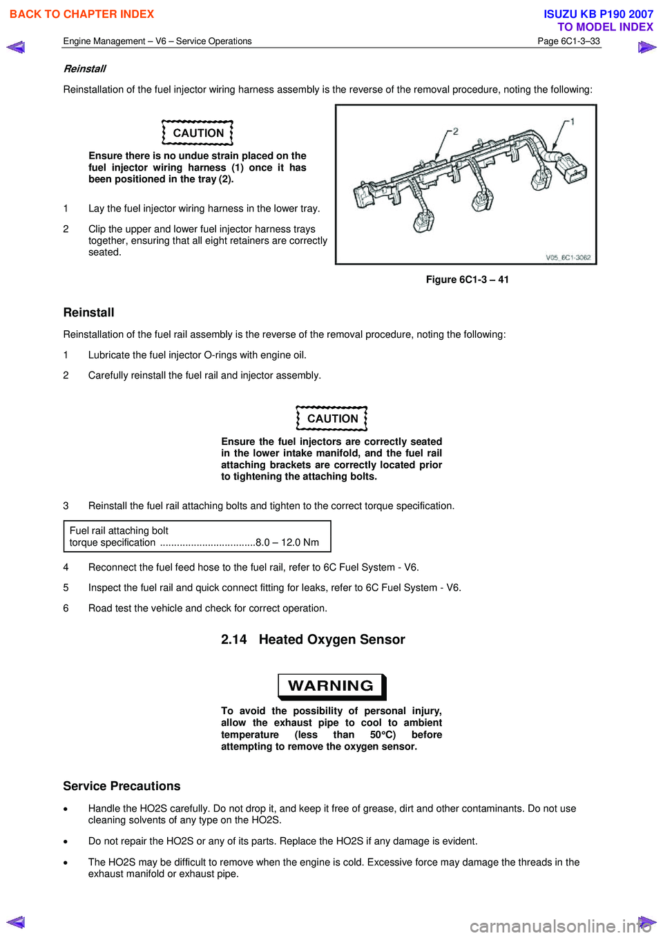
Ensure there is no undue strain placed on the
fuel injector wiring harness (1) once it has
been positioned in the tray (2).
1 Lay the fuel injector wiring harness in the lower tray.
2 Clip the upper and lower fuel injector harness trays together, ensuring that all eight retainers are correctly
seated.
Figure 6C1-3 – 41
Reinstall
Reinstallation of the fuel rail assembly is the reverse of the removal procedure, noting the following:
1 Lubricate the fuel injector O-rings with engine oil.
2 Carefully reinstall the fuel rail and injector assembly.
Ensure the fuel injectors are correctly seated
in the lower intake manifold, and the fuel rail
attaching brackets are correctly located prior
to tightening the attaching bolts.
3 Reinstall the fuel rail attaching bolts and tighten to the correct torque specification. Fuel rail attaching bolt
torque specification ..................................8.0 – 12.0 Nm
4 Reconnect the fuel feed hose to the fuel rail, refer to 6C Fuel System - V6.
5 Inspect the fuel rail and quick connect fitting for leaks, refer to 6C Fuel System - V6.
6 Road test the vehicle and check for correct operation.
2.14 Heated Oxygen Sensor
To avoid the possibility of personal injury,
allow the exhaust pipe to cool to ambient
temperature (less than 50 °
°°
°
C) before
attempting to remove the oxygen sensor.
Service Precautions
• Handle the HO2S carefully. Do not drop it, and keep it free of grease, dirt and other contaminants. Do not use
cleaning solvents of any type on the HO2S.
• Do not repair the HO2S or any of its parts. Replace the HO2S if any damage is evident.
• The HO2S may be difficult to remove when the engine is cold. Excessive force may damage the threads in the
exhaust manifold or exhaust pipe.
BACK TO CHAPTER INDEX
TO MODEL INDEX
ISUZU KB P190 2007
Page 3563 of 6020
Engine Management – V6 – Service Operations Page 6C1-3–39
Disassemble
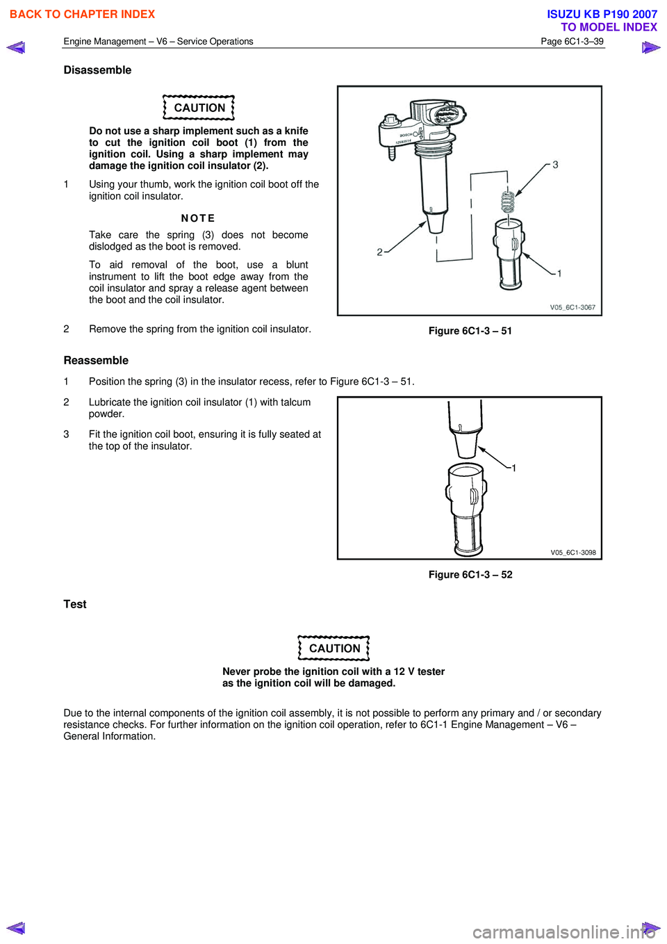
Do not use a sharp implement such as a knife
to cut the ignition coil boot (1) from the
ignition coil. Using a sharp implement may
damage the ignition coil insulator (2).
1 Using your thumb, work the ignition coil boot off the ignition coil insulator.
NOTE
Take care the spring (3) does not become
dislodged as the boot is removed.
To aid removal of the boot, use a blunt
instrument to lift the boot edge away from the
coil insulator and spray a release agent between
the boot and the coil insulator.
2 Remove the spring from the ignition coil insulator.
Figure 6C1-3 – 51
Reassemble
1 Position the spring (3) in the insulator recess, refer to Figure 6C1-3 – 51.
2 Lubricate the ignition coil insulator (1) with talcum powder.
3 Fit the ignition coil boot, ensuring it is fully seated at the top of the insulator.
Figure 6C1-3 – 52
Test
Never probe the ignition coil with a 12 V tester
as the ignition coil will be damaged.
Due to the internal components of the ignition coil assembly, it is not possible to perform any primary and / or secondary
resistance checks. For further information on the ignition coil operation, refer to 6C1-1 Engine Management – V6 –
General Information.
BACK TO CHAPTER INDEX
TO MODEL INDEX
ISUZU KB P190 2007
Page 3564 of 6020

Engine Management – V6 – Service Operations Page 6C1-3–40
Reinstall
Reinstallation of the ignition coil is the reverse of the removal procedure, noting the following:
1 Lubricate the ignition coil sealing rubber (1) with clean engine oil, and the inside of the ignition coil boot (2)
with talcum powder.
Figure 6C1-3 – 53
2 Reinstall the ignition coil by pushing down on the ignition coil to engage the sealing rubber in the camshaft cover.
Ensure the ignition coil is fully seated before
tightening the attaching bolt to the specified
torque.
3 Reinstall the ignition coil bolt and tighten to the correct torque specification. Ignition coil attaching bolt
torque specification ...................................7.0 – 11.0 Nm
4 Road test the vehicle and check for correct operation.
2.16 Intake Air Duct Assembly
Remove
1 Turn the ignition switch off.
2 Disconnect the crankcase ventilation hose (1) from the air intake duct (2).
3 Loosen the two air intake duct retaining clamps (3),
4 Pull the air intake duct away from the throttle body.
5 Pull the air intake duct away from the mass air flow sensor.
Figure 6C1-3 – 54
Reinstall
Reinstallation of the air intake duct is the reverse of the removal procedure, noting the following:
BACK TO CHAPTER INDEX
TO MODEL INDEX
ISUZU KB P190 2007
Page 3567 of 6020
Engine Management – V6 – Service Operations Page 6C1-3–43
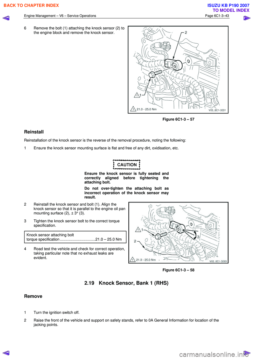
6 Remove the bolt (1) attaching the knock sensor (2) to
the engine block and remove the knock sensor.
Figure 6C1-3 – 57
Reinstall
Reinstallation of the knock sensor is the reverse of the removal procedure, noting the following:
1 Ensure the knock sensor mounting surface is flat and free of any dirt, oxidisation, etc.
Ensure the knock sensor is fully seated and
correctly aligned before tightening the
attaching bolt.
Do not over-tighten the attaching bolt as
incorrect operation of the knock sensor may
result.
2 Reinstall the knock sensor and bolt (1). Align the knock sensor so that it is parallel to the engine oil pan
mounting surface (2), ± 3° (3).
3 Tighten the knock sensor bolt to the correct torque specification.
Knock sensor attaching bolt
torque specification .................................21.0 – 25.0 Nm
4 Road test the vehicle and check for correct operation, taking particular note that no exhaust leaks are
evident.
Figure 6C1-3 – 58
2.19 Knock Sensor, Bank 1 (RHS)
Remove
1 Turn the ignition switch off.
2 Raise the front of the vehicle and support on safety stands, refer to 0A General Information for location of the jacking points.
BACK TO CHAPTER INDEX
TO MODEL INDEX
ISUZU KB P190 2007