2007 ISUZU KB P190 check oil
[x] Cancel search: check oilPage 3867 of 6020
Automatic Transmission – 4L60E – Electrical Diagnosis Page 7C2–81
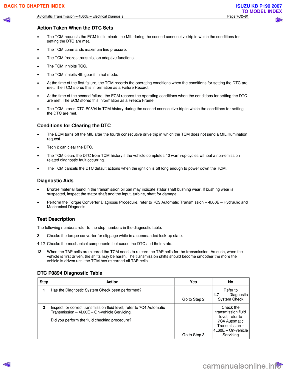
Action Taken When the DTC Sets
• The TCM requests the ECM to illuminate the MIL during the second consecutive trip in which the conditions for
setting the DTC are met.
• The TCM commands maximum line pressure.
• The TCM freezes transmission adaptive functions.
• The TCM inhibits TCC.
• The TCM inhibits 4th gear if in hot mode.
• At the time of the first failure, the TCM records the operating conditions when the conditions for setting the DTC are
met. The TCM stores this information as a Failure Record.
• At the time of the second failure, the ECM records the operating conditions when the conditions for setting the DTC
are met. The ECM stores this information as a Freeze Frame.
• The TCM stores DTC P0894 in TCM history during the second consecutive trip in which the conditions for setting
the DTC are met.
Conditions for Clearing the DTC
• The ECM turns off the MIL after the fourth consecutive drive trip in which the TCM does not send a MIL illumination
request.
• Tech 2 can clear the DTC.
• The TCM clears the DTC from TCM history if the vehicle completes 40 warm-up cycles without a non-emission
related diagnostic fault occurring.
• The TCM cancels the DTC default actions when the ignition is off long enough to power down the TCM.
Diagnostic Aids
•
Bronze material found in the transmission oil pan may indicate stator shaft bushing wear. If bushing wear is
suspected, inspect the stator shaft and the input, turbine, shaft for damage.
• Perform the Torque Converter Diagnosis Procedure, refer to 7C3 Automatic Transmission – 4L60E – Hydraulic and
Mechanical Diagnosis.
Test Description
The following numbers refer to the step numbers in the diagnostic table:
3 Checks the torque converter for slippage while in a commanded lock-up state.
4-12 Checks the mechanical components that cause the DTC and their state.
13 W hen the TAP cells are cleared the TCM needs to relearn the TAP cells for the transmission. As such, when the vehicle is first driven, the shifts may be harsh. The transmission shifts should become smoother the more the
vehicle is driven until the TCM has relearned all TAP cells.
DTC P0894 Diagnostic Table
Step Action Yes No
1 Has the Diagnostic System Check been performed?
Go to Step 2 Refer to
4.7 Diagnostic System Check
2 Inspect for correct transmission fluid level, refer to 7C4 Automatic
Transmission – 4L60E – On-vehicle Servicing.
Did you perform the fluid checking procedure?
Go to Step 3 Check the
transmission fluid level, refer to
7C4 Automatic
Transmission –
4L60E – On-vehicle Servicing
BACK TO CHAPTER INDEX
TO MODEL INDEX
ISUZU KB P190 2007
Page 3872 of 6020
Automatic Transmission – 4L60E – Electrical Diagnosis Page 7C2–86
Step Action Yes No
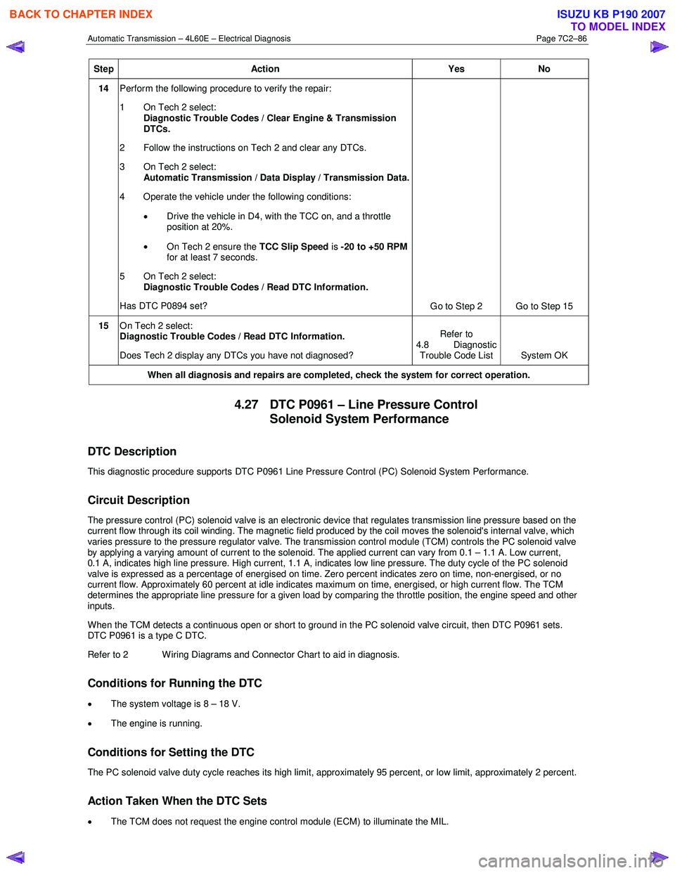
14 Perform the following procedure to verify the repair:
1 On Tech 2 select: Diagnostic Trouble Codes / Clear Engine & Transmission
DTCs.
2 Follow the instructions on Tech 2 and clear any DTCs.
3 On Tech 2 select: Automatic Transmission / Data Display / Transmission Data.
4 Operate the vehicle under the following conditions:
• Drive the vehicle in D4, with the TCC on, and a throttle
position at 20%.
• On Tech 2 ensure the TCC Slip Speed is -20 to +50 RPM
for at least 7 seconds.
5 On Tech 2 select:
Diagnostic Trouble Codes / Read DTC Information.
Has DTC P0894 set? Go to Step 2 Go to Step 15
15 On Tech 2 select:
Diagnostic Trouble Codes / Read DTC Information.
Does Tech 2 display any DTCs you have not diagnosed? Refer to
4.8 Diagnostic Trouble Code List System OK
When all diagnosis and repairs are completed, check the system for correct operation.
4.27 DTC P0961 – Line Pressure Control
Solenoid System Performance
DTC Description
This diagnostic procedure supports DTC P0961 Line Pressure Control (PC) Solenoid System Performance.
Circuit Description
The pressure control (PC) solenoid valve is an electronic device that regulates transmission line pressure based on the
current flow through its coil winding. The magnetic field produced by the coil moves the solenoid's internal valve, which
varies pressure to the pressure regulator valve. The transmission control module (TCM) controls the PC solenoid valve
by applying a varying amount of current to the solenoid. The applied current can vary from 0.1 – 1.1 A. Low current,
0.1 A, indicates high line pressure. High current, 1.1 A, indicates low line pressure. The duty cycle of the PC solenoid
valve is expressed as a percentage of energised on time. Zero percent indicates zero on time, non-energised, or no
current flow. Approximately 60 percent at idle indicates maximum on time, energised, or high current flow. The TCM
determines the appropriate line pressure for a given load by comparing the throttle position, the engine speed and other
inputs.
W hen the TCM detects a continuous open or short to ground in the PC solenoid valve circuit, then DTC P0961 sets.
DTC P0961 is a type C DTC.
Refer to 2 W iring Diagrams and Connector Chart to aid in diagnosis.
Conditions for Running the DTC
• The system voltage is 8 – 18 V.
• The engine is running.
Conditions for Setting the DTC
The PC solenoid valve duty cycle reaches its high limit, approximately 95 percent, or low limit, approximately 2 percent.
Action Taken When the DTC Sets
• The TCM does not request the engine control module (ECM) to illuminate the MIL.
BACK TO CHAPTER INDEX
TO MODEL INDEX
ISUZU KB P190 2007
Page 3894 of 6020
Automatic Transmission – 4L60E – Electrical Diagnosis Page 7C2–108
Step Action Yes No
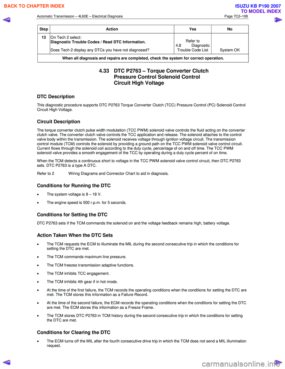
13 On Tech 2 select:
Diagnostic Trouble Codes / Read DTC Information.
Does Tech 2 display any DTCs you have not diagnosed? Refer to
4.8 Diagnostic Trouble Code List System OK
When all diagnosis and repairs are completed, check the system for correct operation.
4.33 DTC P2763 – Torque Converter Clutch
Pressure Control Solenoid Control
Circuit High Voltage
DTC Description
This diagnostic procedure supports DTC P2763 Torque Converter Clutch (TCC) Pressure Control (PC) Solenoid Control
Circuit High Voltage.
Circuit Description
The torque converter clutch pulse width modulation (TCC PW M) solenoid valve controls the fluid acting on the converter
clutch valve. The converter clutch valve controls the TCC application and release. The solenoid attaches to the control
valve body within the transmission. The solenoid receives voltage through ignition voltage circuit. The transmission
control module (TCM) controls the solenoid by providing a ground path on the TCC PW M solenoid valve control circuit.
Current flows through the solenoid coil according to the duty cycle, percentage of on and off time. The TCC PWM
solenoid valve provides a smooth engagement of the TCC by operating during a duty cycle percent of on time.
When the TCM detects a continuous short to voltage in the TCC PW M solenoid valve control circuit, then DTC P2763
sets. DTC P2763 is a type A DTC.
Refer to 2 W iring Diagrams and Connector Chart to aid in diagnosis.
Conditions for Running the DTC
• The system voltage is 8 – 18 V.
• The engine speed is 500 r.p.m. for 5 seconds.
Conditions for Setting the DTC
DTC P2763 sets if the TCM commands the solenoid on and the voltage feedback remains high, battery voltage.
Action Taken When the DTC Sets
• The TCM requests the ECM to illuminate the MIL during the second consecutive trip in which the conditions for
setting the DTC are met.
• The TCM commands maximum line pressure.
• The TCM freezes transmission adaptive functions.
• The TCM inhibits TCC engagement.
• The TCM inhibits 4th gear if in hot mode.
• At the time of the first failure, the TCM records the operating conditions when the conditions for setting the DTC are
met. The TCM stores this information as a Failure Record.
• At the time of the second failure, the ECM records the operating conditions when the conditions for setting the DTC
are met. The ECM stores this information as a Freeze Frame.
• The TCM stores DTC P2763 in TCM history during the second consecutive trip in which the conditions for setting
the DTC are met.
Conditions for Clearing the DTC
• The ECM turns off the MIL after the fourth consecutive drive trip in which the TCM does not send a MIL illumination
request.
BACK TO CHAPTER INDEX
TO MODEL INDEX
ISUZU KB P190 2007
Page 3919 of 6020

Automatic Transmission – 4L60E – On-vehicle Servicing Page 7C4–6
6 Lift the locking lever (1) on the transmission fluid
indicator, then remove the indicator from the filler
tube (2) and check the fluid colour, condition and level.
Do not overfill the transmission. Overfilling
can cause aeration resulting in fluid loss,
shift complaints and possible damage to the
transmission.
7 If the transmission fluid level is low, add only enough of the recommended fluid until
its level shows onto the
crosshatch hot area (3) of the fluid indicator.
Figure 7C4 – 1
2.2 Reverse Flush and Flow Rate Test
It is essential to perform a reverse flush and oil cooler flow rate test after any of the following:
• the transmission is repaired or replaced,
• fluid contamination is suspected, or
• whenever the oil pump and/or torque converter is replaced.
NOTE
The reverse flush must be completed prior to
conducting a flow rate test.
Reverse Flush
1 Disconnect both cooler hose/line assemblies at the transmission and at the radiator cooler, refer to 3.17 Transmission Cooler Line/Hose Assemblies.
2 Check the cooler hose/line to radiator cooler fittings for damage, replace as required.
To avoid personal injury, wear safety glasses
when using compressed air.
3 Carefully check the radiator cooler lower fitting to see if any foreign material is evident at this point. If foreign material is found, remove it with a suitable tool and/or compressed air at a reduced pressure of approximately
345 kPa blown in the reverse direction through the cooler.
4 Using compressed air at a reduced pressure of approximately 345 kPa blown in a reverse direction, clean the cooler hose/line assemblies.
5 Reconnect the cooler outlet line to the transmission and both cooler hose/line assemblies to the radiator cooler fittings, refer to 3.17 Transmission Cooler Line/Hose Assemblies.
NOTE
Do not reconnect the cooler inlet line at the
transmission end. This line needs to be left
disconnected to perform the flow rate test.
6 Perform the flow rate test, refer to Flow Rate Test in this Section.
BACK TO CHAPTER INDEX
TO MODEL INDEX
ISUZU KB P190 2007
Page 3923 of 6020
Automatic Transmission – 4L60E – On-vehicle Servicing Page 7C4–10
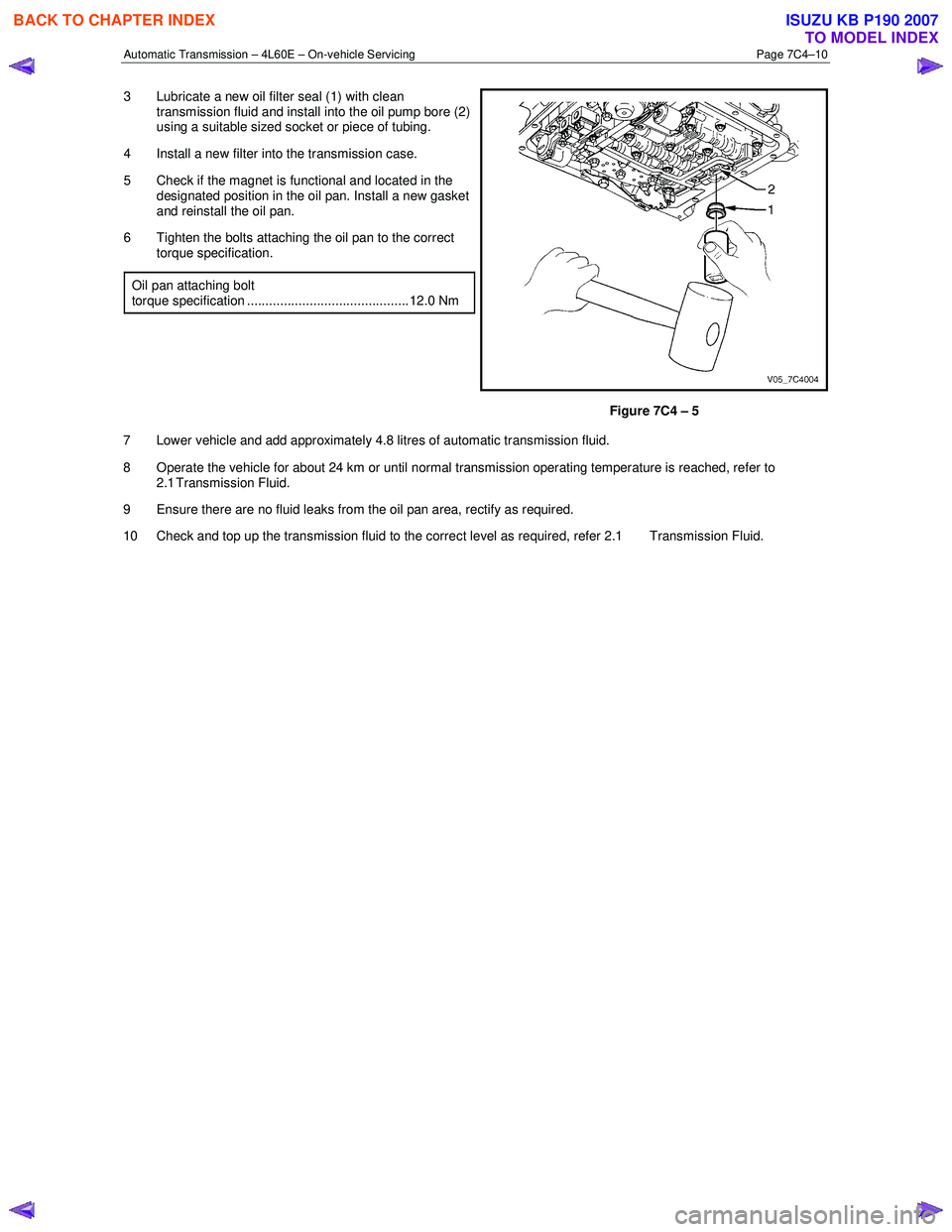
3 Lubricate a new oil filter seal (1) with clean
transmission fluid and install into the oil pump bore (2)
using a suitable sized socket or piece of tubing.
4 Install a new filter into the transmission case.
5 Check if the magnet is functional and located in the designated position in the oil pan. Install a new gasket
and reinstall the oil pan.
6 Tighten the bolts attaching the oil pan to the correct torque specification.
Oil pan attaching bolt
torque specification ............................................ 12.0 Nm
Figure 7C4 – 5
7 Lower vehicle and add approximately 4.8 litres of automatic transmission fluid.
8 Operate the vehicle for about 24 km or until normal transmission operating temperature is reached, refer to 2.1 Transmission Fluid.
9 Ensure there are no fluid leaks from the oil pan area, rectify as required.
10 Check and top up the transmission fluid to the correct level as required, refer 2.1 Transmission Fluid.
BACK TO CHAPTER INDEX
TO MODEL INDEX
ISUZU KB P190 2007
Page 3933 of 6020
Automatic Transmission – 4L60E – On-vehicle Servicing Page 7C4–20
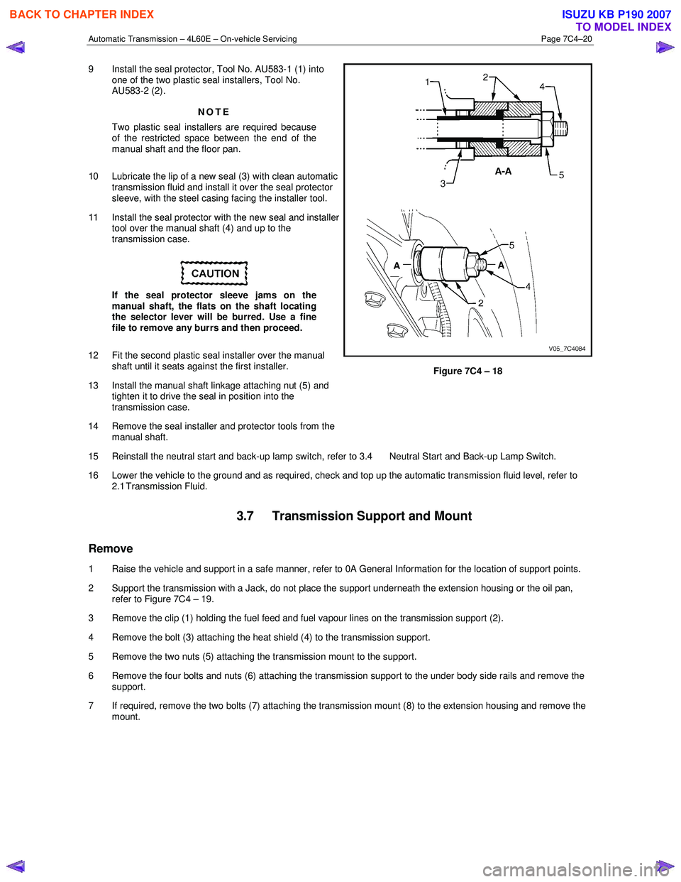
9 Install the seal protector, Tool No. AU583-1 (1) into
one of the two plastic seal installers, Tool No.
AU583-2 (2).
NOTE
Two plastic seal installers are required because
of the restricted space between the end of the
manual shaft and the floor pan.
10 Lubricate the lip of a new seal (3) with clean automatic transmission fluid and install it over the seal protector
sleeve, with the steel casing facing the installer tool.
11 Install the seal protector with the new seal and installer tool over the manual shaft (4) and up to the
transmission case.
If the seal protector sleeve jams on the
manual shaft, the flats on the shaft locating
the selector lever will be burred. Use a fine
file to remove any burrs and then proceed.
12 Fit the second plastic seal installer over the manual shaft until it seats against the first installer.
13 Install the manual shaft linkage attaching nut (5) and tighten it to drive the seal in position into the
transmission case.
14 Remove the seal installer and protector tools from the manual shaft.
Figure 7C4 – 18
15 Reinstall the neutral start and back-up lamp switch, refer to 3.4 Neutral Start and Back-up Lamp Switch.
16 Lower the vehicle to the ground and as required, check and top up the automatic transmission fluid level, refer to 2.1 Transmission Fluid.
3.7 Transmission Support and Mount
Remove
1 Raise the vehicle and support in a safe manner, refer to 0A General Information for the location of support points.
2 Support the transmission with a Jack, do not place the support underneath the extension housing or the oil pan, refer to Figure 7C4 – 19.
3 Remove the clip (1) holding the fuel feed and fuel vapour lines on the transmission support (2).
4 Remove the bolt (3) attaching the heat shield (4) to the transmission support.
5 Remove the two nuts (5) attaching the transmission mount to the support.
6 Remove the four bolts and nuts (6) attaching the transmission support to the under body side rails and remove the support.
7 If required, remove the two bolts (7) attaching the transmission mount (8) to the extension housing and remove the mount.
BACK TO CHAPTER INDEX
TO MODEL INDEX
ISUZU KB P190 2007
Page 3935 of 6020
Automatic Transmission – 4L60E – On-vehicle Servicing Page 7C4–22
3.8 Extension Housing Oil Seal, RWD
Replace
1 Raise the vehicle and support in a safe manner, refer to 0A General Information for the location of support points.
2 Remove the rear propeller shaft, refer to 4A Propeller Shaft.
3 Place a suitable size drip tray underneath rear of transmission.
Take care not to scratch the machined seal
recess in the extension housing as
transmission fluid may weep past the outer
diameter of the installed seal.
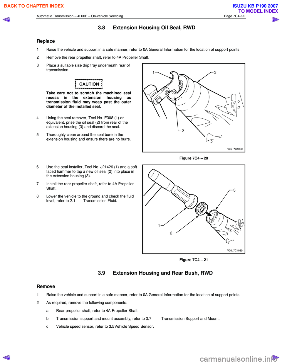
4 Using the seal remover, Tool No. E308 (1) or equivalent, prise the oil seal (2) from rear of the
extension housing (3) and discard the seal.
5 Thoroughly clean around the seal bore in the extension housing and ensure there are no burrs.
Figure 7C4 – 20
6 Use the seal installer, Tool No. J21426 (1) and a soft faced hammer to tap a new oil seal (2) into place in
the extension housing (3).
7 Install the rear propeller shaft, refer to 4A Propeller Shaft.
8 Lower the vehicle to the ground and check the fluid level, refer to 2.1 Transmission Fluid.
Figure 7C4 – 21
3.9 Extension Housing and Rear Bush, RWD
Remove
1 Raise the vehicle and support in a safe manner, refer to 0A General Information for the location of support points.
2 As required, remove the following components:
a Rear propeller shaft, refer to 4A Propeller Shaft.
b Transmission support and mount assembly, refer to 3.7 Transmission Support and Mount.
c Vehicle speed sensor, refer to 3.5 Vehicle Speed Sensor.
BACK TO CHAPTER INDEX
TO MODEL INDEX
ISUZU KB P190 2007
Page 3943 of 6020

Automatic Transmission – 4L60E – On-vehicle Servicing Page 7C4–30
12 Road test until the transmission has reached operating temperature. Re-check the fluid level and for any fluid leaks
from the oil pan area, refer to 2.1 Transmission Fluid.
3.14 Control Valve Body
Remove
1 Partially remove the control valve body harness until it hangs from the pass-thru connector, refer to
3.13 Control Valve Body Harness.
2 Remove the three long bolts (1) and the two short bolts (2) attaching the transmission fluid pressure
(TFP) manual valve position switch assembly (3),
remove the switch and discard the shield (4).
3 Remove the attaching bolt (5) and the manual detent spring (6).
Figure 7C4 – 37
In the following procedure support the
control valve body before removing the last
bolt.
NOTE
The removal may be more manageable by
removing the bolts in a spiral pattern starting
from the outside, removing the centre bolt last.
4 Remove the fourteen remaining bolts (1) attaching the control valve body.
Figure 7C4 – 38
BACK TO CHAPTER INDEX
TO MODEL INDEX
ISUZU KB P190 2007