2007 ISUZU KB P190 ECO mode
[x] Cancel search: ECO modePage 1603 of 6020
ENGINE ELECTRICAL (4JK1/4JJ1) 6D-15
Starter Motor
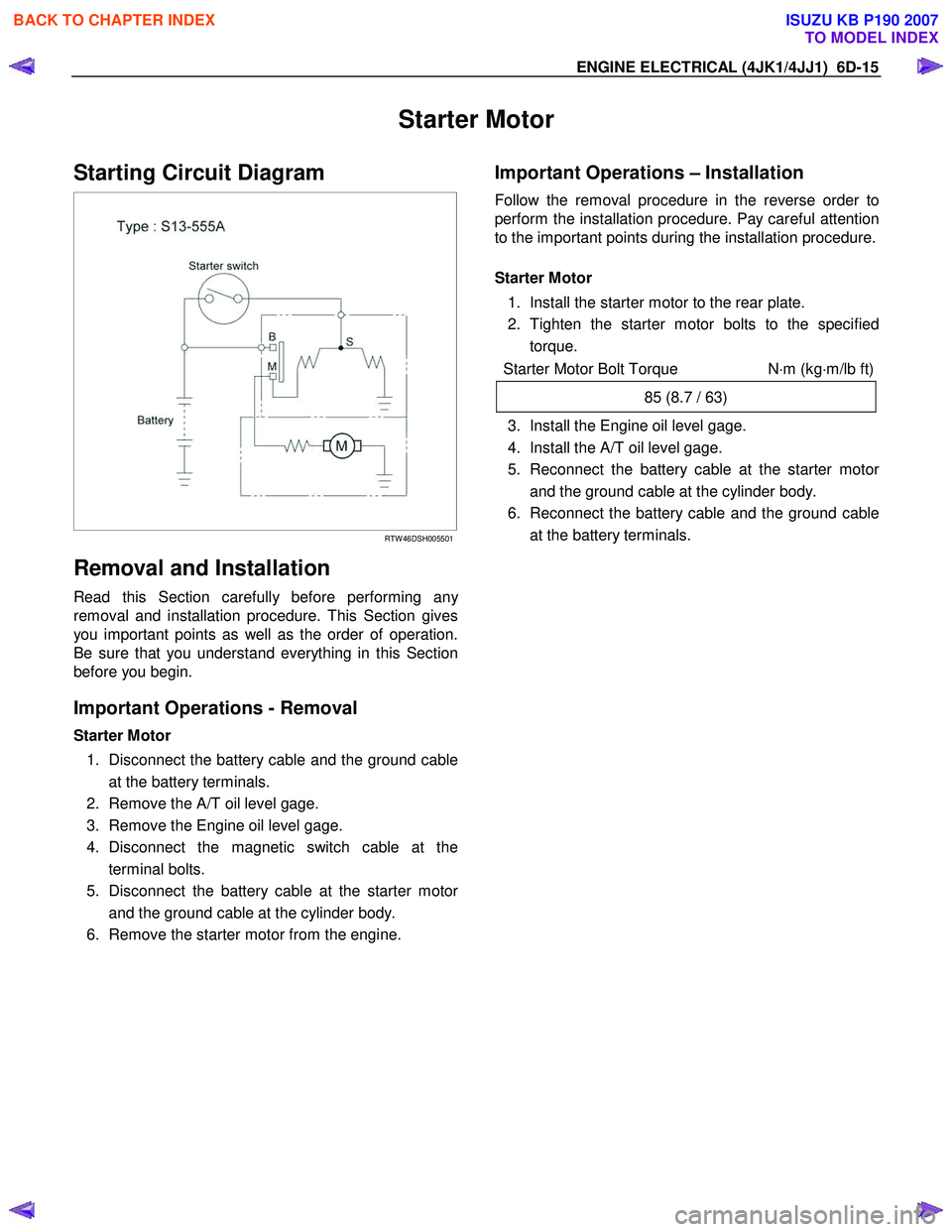
Starting Circuit Diagram
RTW 46DSH005501
Removal and Installation
Read this Section carefully before performing any
removal and installation procedure. This Section gives
you important points as well as the order of operation.
Be sure that you understand everything in this Section
before you begin.
Important Operations - Removal
Starter Motor
1. Disconnect the battery cable and the ground cable at the battery terminals.
2. Remove the A/T oil level gage.
3. Remove the Engine oil level gage.
4. Disconnect the magnetic switch cable at the terminal bolts.
5. Disconnect the battery cable at the starter moto
r
and the ground cable at the cylinder body.
6. Remove the starter motor from the engine.
Important Operations – Installation
Follow the removal procedure in the reverse order to
perform the installation procedure. Pay careful attention
to the important points during the installation procedure.
Starter Motor
1. Install the starter motor to the rear plate.
2. Tighten the starter motor bolts to the specified torque.
Starter Motor Bolt Torque N⋅m (kg ⋅m/lb ft)
85 (8.7 / 63)
3. Install the Engine oil level gage.
4. Install the A/T oil level gage.
5. Reconnect the battery cable at the starter moto
r
and the ground cable at the cylinder body.
6. Reconnect the battery cable and the ground cable at the battery terminals.
BACK TO CHAPTER INDEX
TO MODEL INDEX
ISUZU KB P190 2007
Page 1615 of 6020
ENGINE ELECTRICAL (4JK1/4JJ1) 6D-27
Magnetic Switch
The following tests must be performed with the starter
motor fully assembled.
The yoke lead wire must be disconnected from the “M”
terminal.
To prevent coil burning, complete each test as quickl
y
as possible (within three to five seconds).
Temporarily connect the solenoid switch between the
clutch and the housing and run the following test.
Complete each test within three to five seconds.
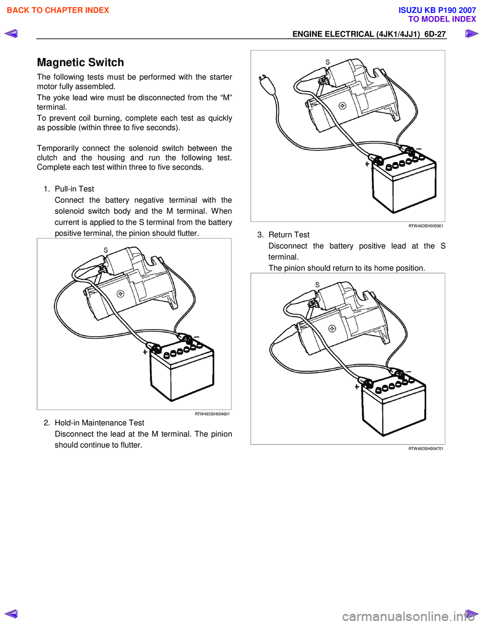
1. Pull-in Test
Connect the battery negative terminal with the solenoid switch body and the M terminal. W hen
current is applied to the S terminal from the batter
y
positive terminal, the pinion should flutter.
RTW 46DSH004601
2. Hold-in Maintenance Test
Disconnect the lead at the M terminal. The pinion should continue to flutter.
RTW 46DSH005901
3. Return Test
Disconnect the battery positive lead at the S terminal.
The pinion should return to its home position.
RTW 46DSH004701
BACK TO CHAPTER INDEX
TO MODEL INDEX
ISUZU KB P190 2007
Page 1619 of 6020
6E-2 ENGINE CONTROL SYSTEM (4JK1/4JJ1)
DTC P2127 or P2128 (Flash Code 122) . . . . 6E-265
DTC P2132 or P2133 (Flash Code 123) . . . . 6E-269
DTC P2138, P2139 or P2140 (Flash Code 124, 125 or 126) . . . . . . . . . . . . 6E-274
DTC P2146, P2147 or P2148 (Flash Code 158) . . . . . . . . . . . . . . . . . . . . . 6E-280
DTC P2149, P2150 or P2151 (Flash Code 159) . . . . . . . . . . . . . . . . . . . . . 6E-284
DTC P2227 (Flash Code 71) . . . . . . . . . . . . . 6E-288
DTC P2228 or P2229 (Flash Code 71) . . . . . 6E-291
DTC P2621 or P2622 (Flash Code 94) . . . . . 6E-295
DTC U0001 or U0101 Flash Code 84 or 85) . . . . . . . . . . . . . . . . . . 6E-298
DTC U0167 (Flash Code 177) . . . . . . . . . . . . 6E-299
EGR Control System Check. . . . . . . . . . . . . . 6E-300
Glow Control System Check . . . . . . . . . . . . . 6E-304
In-Tank Fuel Pump System Check . . . . . . . . . 6E-309
Cruise Control System Check . . . . . . . . . . . . 6E-312
Turbocharger Control System Check . . . . . . . 6E-318
Symptoms - Engine Controls . . . . . . . . . . . . . . 6E-321 Symptoms - Engine Controls . . . . . . . . . . . . . 6E-321
Intermittent Conditions . . . . . . . . . . . . . . . . . . 6E-323
Hard Start . . . . . . . . . . . . . . . . . . . . . . . . . . . . 6E-326
Rough, Unstable, or Incorrect Idle and Stalling. . . . . . . . . . . . . . . . . . . . . . . . . . . . . . 6E-328
High Idle Speed . . . . . . . . . . . . . . . . . . . . . . . 6E-330
Cuts Out . . . . . . . . . . . . . . . . . . . . . . . . . . . . . 6E-331
Surges . . . . . . . . . . . . . . . . . . . . . . . . . . . . . . 6E-332
Lack of Power, Sluggishness or Sponginess . . . . . . . . . . . . . . . . . . . . . . . . . . 6E-334
Hesitation, Sag or Stumble. . . . . . . . . . . . . . . 6E-336
Abnormal Combustion Noise . . . . . . . . . . . . . 6E-338
Poor Fuel Economy . . . . . . . . . . . . . . . . . . . . 6E-339
Excessive Smoke (Black Smoke) . . . . . . . . . 6E-341
Excessive Smoke (White Smoke) . . . . . . . . . 6E-343
Repair Instructions . . . . . . . . . . . . . . . . . . . . . . 6E-345 Engine Control Module (ECM) Replacement . . . . . . . . . . . . . . . . . . . . . . . . . 6E-345
Service Programming System (SPS) Description . . . . . . . . . . . . . . . . . . . . . . . . . . 6E-347
Service Programming System (SPS) (Remote Procedure) . . . . . . . . . . . . . . . . . . . 6E-348
Service Programming System (SPS) (Pass-Thru Procedure) . . . . . . . . . . . . . . . . . 6E-349
Description and Operation . . . . . . . . . . . . . . . . 6E-351 Engine Control Module (ECM) Description . . 6E-351
Engine Control Component Description . . . . . 6E-353
Fuel System Description . . . . . . . . . . . . . . . . 6E-357
Fuel System Component Description. . . . . . . 6E-358
Fuel Injection System Description . . . . . . . . . 6E-362
Exhaust Gas Recirculation (EGR) System Description . . . . . . . . . . . . . . . . . . . . 6E-363
Turbocharger Description . . . . . . . . . . . . . . . . 6E-364
Special Tools and Equipment . . . . . . . . . . . . . . 6E-366 Special Tools and Equipment . . . . . . . . . . . . . 6E-366
BACK TO CHAPTER INDEX
TO MODEL INDEX
ISUZU KB P190 2007
Page 1621 of 6020
6E-4 ENGINE CONTROL SYSTEM (4JK1/4JJ1)
Diagnostic Trouble Code (DTC) Type
Definitions
Emission Related DTC
Action Taken When the DTC Sets - Type A • The ECM illuminates the malfunction indicator lamp (MIL) when the diagnostic runs and fails.
• The ECM records the operating conditions at the time the diagnostic fails. The ECM stores this
information in the Freeze Frame/ Failure Records.
Action Taken When the DTC Sets - Type B • The ECM illuminates the MIL on the second consecutive driving cycle when the diagnostic runs
and fails.
• The ECM records the operating conditions at the time the diagnostic fails. The first time the
diagnostic fails, the ECM stores this information in
the Failure Records. If the diagnostic reports a
failure on the second consecutive driving cycle, the
ECM records the operating conditions at the time
of failure and stores this information in the Freeze
Frame and updates the Failure Records.
Conditions for Clearing the MIL/ DTC - Type A or
Ty p e B
• The ECM turns OFF the MIL after 3 consecutive driving cycles when the diagnostic runs and does
not fail. (Euro 4 Specification)
• The ECM turns OFF the MIL after 1 driving cycle when the diagnostic runs and does not fail. (Except
Euro 4 Specification)
• A current DTC clears when the diagnostic runs and passes after 1 driving cycle.
• A history DTC clears after 40 consecutive warm-up cycles, if no failures are reported. • Use a scan tool to clear the MIL and the DTC.
Non-Emissions Related DTCs
Action Taken When the DTC Sets - Type C
• The ECM illuminates the Service Vehicle Soon (SVS) lamp when the diagnostic runs and fails.
• The ECM records the operating conditions at the time the diagnostic fails. The ECM stores this
information in the Failure Records.
Conditions for Clearing the SVS Lamp/ DTC - Type
C
• The ECM turns OFF the SVS lamp after 1 driving cycle when the diagnostic runs and does not fail.
• A current DTC clears when the diagnostic runs and passes after 1 driving cycle.
• A history DTC clears after 40 consecutive warm-up cycles, if no failures are reported.
• Use a scan tool to clear the SVS lamp and the DTC.
Action Taken When the DTC Sets - Type D • The ECM will not illuminate the MIL or SVS lamp.
• The ECM records the operating conditions at the time the diagnostic fails. The ECM stores this
information in the Failure Records.
Conditions for Clearing the DTC - Type D • A current DTC clears when the diagnostic runs and passes after 1 driving cycle.
• A history DTC clears after 40 consecutive warm-up cycles, if no failures are reported.
• Use a scan tool to clear the DTC.
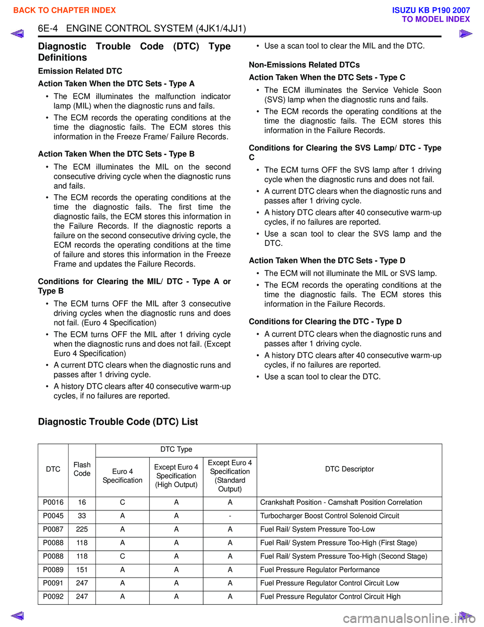
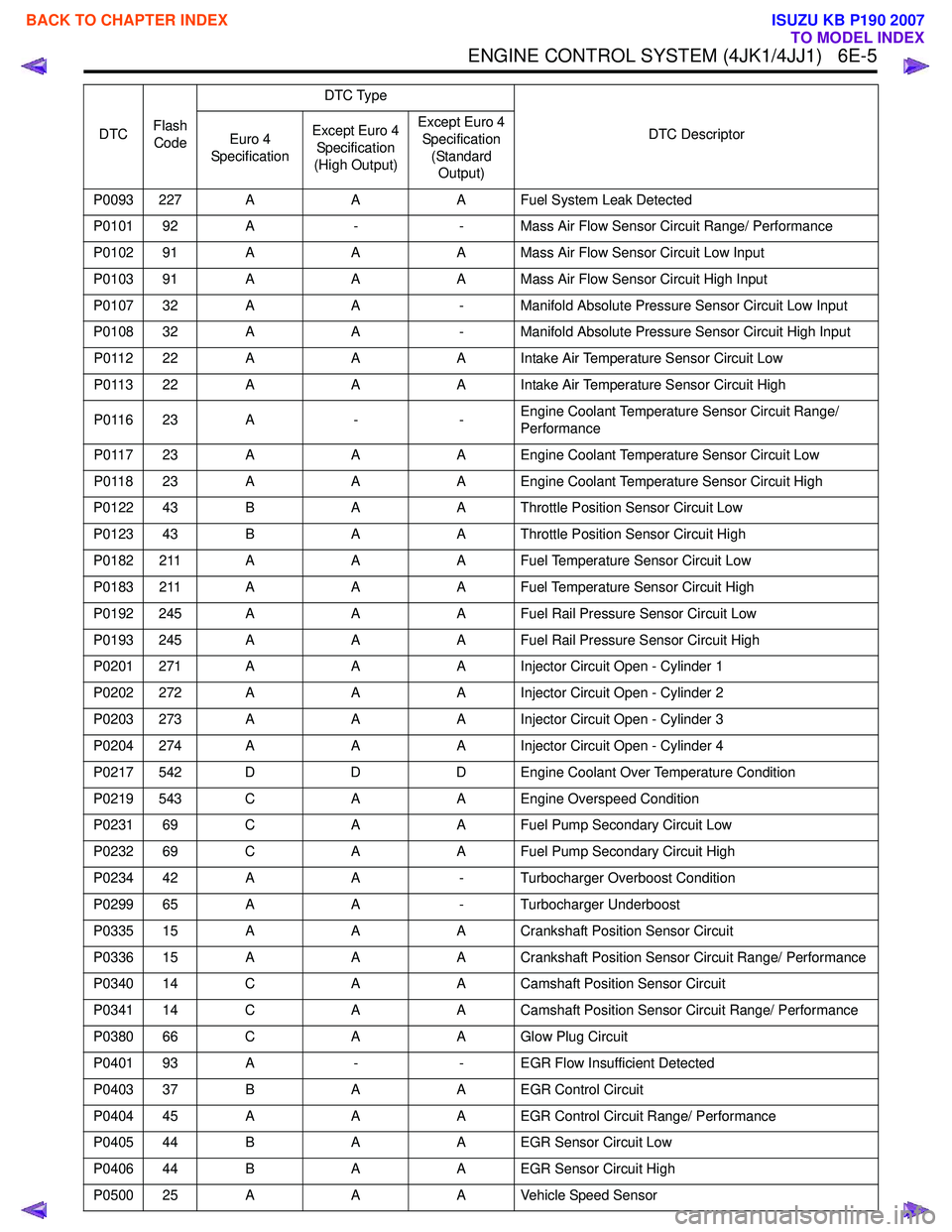
Diagnostic Trouble Code (DTC) List
DTC Flash
Code DTC Type
DTC Descriptor
Euro 4
Specification Except Euro 4
Specification
(High Output) Except Euro 4
Specification
(Standard Output)
P0016 16 C AA Crankshaft Position - Camshaft Position Correlation
P0045 33 A A- Turbocharger Boost Control Solenoid Circuit
P0087 225 A AA Fuel Rail/ System Pressure Too-Low
P0088 118 A AA Fuel Rail/ System Pressure Too-High (First Stage)
P0088 118 C AA Fuel Rail/ System Pressure Too-High (Second Stage)
P0089 151 A AA Fuel Pressure Regulator Performance
P0091 247 A AA Fuel Pressure Regulator Control Circuit Low
P0092 247 A AA Fuel Pressure Regulator Control Circuit High
BACK TO CHAPTER INDEX
TO MODEL INDEX
ISUZU KB P190 2007
Page 1622 of 6020
ENGINE CONTROL SYSTEM (4JK1/4JJ1) 6E-5
P0093 227 AAA Fuel System Leak Detected
P0101 92 A -- Mass Air Flow Sensor Circuit Range/ Performance
P0102 91 A AA Mass Air Flow Sensor Circuit Low Input
P0103 91 A AA Mass Air Flow Sensor Circuit High Input
P0107 32 A A- Manifold Absolute Pressure Sensor Circuit Low Input
P0108 32 A A- Manifold Absolute Pressure Sensor Circuit High Input
P0112 22 A AA Intake Air Temperature Sensor Circuit Low
P0113 22 A AA Intake Air Temperature Sensor Circuit High
P0116 23 A --Engine Coolant Temperature Sensor Circuit Range/
Performance
P0117 23 A AA Engine Coolant Temperature Sensor Circuit Low
P0118 23 A AA Engine Coolant Temperature Sensor Circuit High
P0122 43 B AA Throttle Position Sensor Circuit Low
P0123 43 B AA Throttle Position Sensor Circuit High
P0182 211 A AA Fuel Temperature Sensor Circuit Low
P0183 211 A AA Fuel Temperature Sensor Circuit High
P0192 245 A AA Fuel Rail Pressure Sensor Circuit Low
P0193 245 A AA Fuel Rail Pressure Sensor Circuit High
P0201 271 A AA Injector Circuit Open - Cylinder 1
P0202 272 A AA Injector Circuit Open - Cylinder 2
P0203 273 A AA Injector Circuit Open - Cylinder 3
P0204 274 A AA Injector Circuit Open - Cylinder 4
P0217 542 D DD Engine Coolant Over Temperature Condition
P0219 543 C AA Engine Overspeed Condition
P0231 69 C AA Fuel Pump Secondary Circuit Low
P0232 69 C AA Fuel Pump Secondary Circuit High
P0234 42 A A- Turbocharger Overboost Condition
P0299 65 A A- Turbocharger Underboost
P0335 15 A AA Crankshaft Position Sensor Circuit
P0336 15 A AA Crankshaft Position Sensor Circuit Range/ Performance
P0340 14 C AA Camshaft Position Sensor Circuit
P0341 14 C AA Camshaft Position Sensor Circuit Range/ Performance
P0380 66 C AA Glow Plug Circuit
P0401 93 A -- EGR Flow Insufficient Detected
P0403 37 B AA EGR Control Circuit
P0404 45 A AA EGR Control Circuit Range/ Performance
P0405 44 B AA EGR Sensor Circuit Low
P0406 44 B AA EGR Sensor Circuit High
P0500 25 A AA Vehicle Speed Sensor
DTC
Flash
Code DTC Type
DTC Descriptor
Euro 4
Specification Except Euro 4
Specification
(High Output) Except Euro 4
Specification (Standard Output)
BACK TO CHAPTER INDEX
TO MODEL INDEX
ISUZU KB P190 2007
Page 1661 of 6020
6E-44 ENGINE CONTROL SYSTEM (4JK1/4JJ1)
Diagnostic Starting Point - Engine Controls
Begin the system diagnosis with Diagnostic System
Check - Engine Controls. The Diagnostic System
Check - Engine Controls will provide the following
information:
• The identification of the control modules which command the system.
• The ability of the control modules to communicate through the serial data circuit.
• The identification of any stored diagnostic trouble codes (DTCs) and the their statuses.
The use of the Diagnostic System Check - Engine
Controls will identify the correct procedure for
diagnosing the system and where the procedure is
located.
Important: Engine Control System Check Sheet must
be used to verify the complaint vehicle, you need to
know the correct (normal) operating behavior of the
system and verify that the customer complaint is a valid
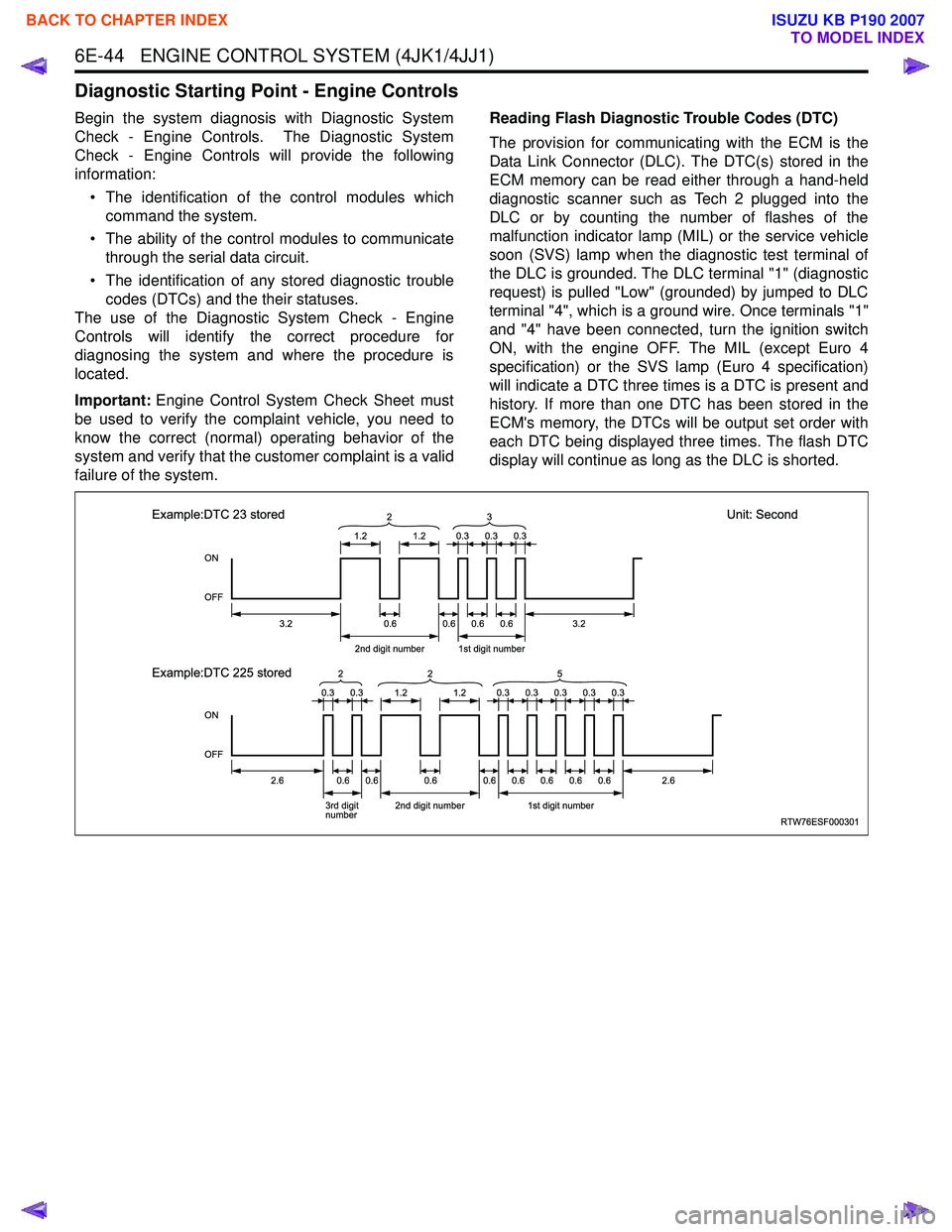
failure of the system. Reading Flash Diagnostic Trouble Codes (DTC)
The provision for communicating with the ECM is the
Data Link Connector (DLC). The DTC(s) stored in the
ECM memory can be read either through a hand-held
diagnostic scanner such as Tech 2 plugged into the
DLC or by counting the number of flashes of the
malfunction indicator lamp (MIL) or the service vehicle
soon (SVS) lamp when the diagnostic test terminal of
the DLC is grounded. The DLC terminal "1" (diagnostic
request) is pulled "Low" (grounded) by jumped to DLC
terminal "4", which is a ground wire. Once terminals "1"
and "4" have been connected, turn the ignition switch
ON, with the engine OFF. The MIL (except Euro 4
specification) or the SVS lamp (Euro 4 specification)
will indicate a DTC three times is a DTC is present and
history. If more than one DTC has been stored in the
ECM's memory, the DTCs will be output set order with
each DTC being displayed three times. The flash DTC
display will continue as long as the DLC is shorted.
RTW76ESF000301
ON
OFF
ON
OFF
1.2
3.2
2.62.6
2nd digit number1st digit number
3.20.6 2
1.2
0.60.60.6
0.30.30.3
0.30.30.30.30.3
Example:DTC 23 stored
Unit: Second
Example:DTC 225 stored
3rd digit
number 2nd digit number1st digit number
0.60.60.60.60.60.60.60.6
3
0.30.31.21.2
2
25
BACK TO CHAPTER INDEX
TO MODEL INDEX
ISUZU KB P190 2007
Page 1663 of 6020

6E-46 ENGINE CONTROL SYSTEM (4JK1/4JJ1)
3Notice:
If an immobilizer system is active the ECM
will disable the fuel injection causing the engine to
stall immediately after starting and energize the
starter cut relay to disable cranking.
Attempt to crank the engine.
Does the engine crank? —
Go to Step 4 Go to Step 5
4 Attempt to start the engine.
Does the engine start and idle? —
Go to Step 6 Go to Engine
Cranks but Does
Not Run
5 Does the scan tool display ECM DTCs P0615,
P0633, P161B or U0167?
—
Go to Applicable DTC Problem is relating
to starting system. Refer to the
applicable
diagnostic chart in starting system
6 Select the DTC display function for the following
control modules: •ECM
• ICU (If so equipped)
• TCM (AISIN A/T only)
Does the scan tool display any DTCs? —
Go to Step 7 Go to Step 11
7 Does the scan tool display DTCs which begin with
U or other control module communication fault
DTCs? —
Go to Applicable
DTC Go to Step 8
8 Does the scan tool display ECM DTCs P0601,
P0602, P0604, P0606 or P1621? —Go to Applicable
DTC Go to Step 9
9 Does the scan tool display ECM DTCs P0562 or
P0563, P156A or P156B? —
Go to Applicable
DTC Go to Step 10
10 Is there any other code in any controller that has
not been diagnosed? —Go to Applicable
DTC Go to Step 11
11 Is the customer’s concern with the automatic
transmission? —Go to Diagnostic
System Check - Transmission
Controls Go to Step 12
12 Is the customer’s concern with the immobilizer
system? —Go to Diagnostic
System Check - Immobilizer
Controls Go to Step 13
13 1. Review the following symptoms.
2. Refer to the applicable symptom diagnostic table:
• Hard Start
• Rough, Unstable, or Incorrect Idle and Stalling
• High Idle Speed
•Cuts Out
• Surges
• Lack of Power, Sluggishness, or Sponginess
• Hesitation, Sag, Stumble
• Abnormal Combustion Noise
• Poor Fuel Economy
• Excessive Smoke (Black Smoke)
• Excessive Smoke (White Smoke)
Did you find and correct the condition? —
System OK Go to Intermittent
Conditions
Step
Action Value(s)Yes No
BACK TO CHAPTER INDEX
TO MODEL INDEX
ISUZU KB P190 2007
Page 1666 of 6020
ENGINE CONTROL SYSTEM (4JK1/4JJ1) 6E-49
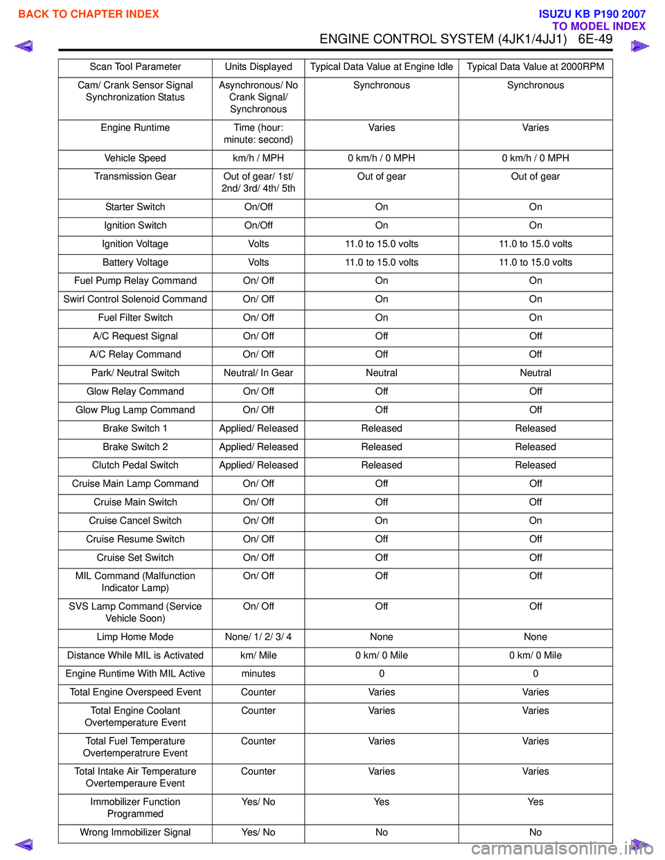
Cam/ Crank Sensor Signal Synchronization Status Asynchronous/ No
Crank Signal/ Synchronous Synchronous Synchronous
Engine Runtime Time (hour: minute: second) Va r i e s
Va r i e s
Vehicle Speed km/h / MPH0 km/h / 0 MPH 0 km/h / 0 MPH
Transmission Gear Out of gear/ 1st/ 2nd/ 3rd/ 4th/ 5th Out of gear
Out of gear
Starter Switch On/OffOn On
Ignition Switch On/OffOn On
Ignition Voltage Volts11.0 to 15.0 volts 11.0 to 15.0 volts
Battery Voltage Volts11.0 to 15.0 volts 11.0 to 15.0 volts
Fuel Pump Relay Command On/ Off OnOn
Swirl Control Solenoid Command On/ Off OnOn
Fuel Filter Switch On/ OffOn On
A/C Request Signal On/ OffOff Off
A/C Relay Command On/ OffOff Off
Park/ Neutral Switch Neutral/ In Gear NeutralNeutral
Glow Relay Command On/ OffOff Off
Glow Plug Lamp Command On/ Off OffOff
Brake Switch 1 Applied/ Released Released Released
Brake Switch 2 Applied/ Released Released Released
Clutch Pedal Switch Applied/ Released ReleasedReleased
Cruise Main Lamp Command On/ Off OffOff
Cruise Main Switch On/ OffOff Off
Cruise Cancel Switch On/ OffOn On
Cruise Resume Switch On/ OffOff Off
Cruise Set Switch On/ OffOff Off
MIL Command (Malfunction Indicator Lamp) On/ Off
Off Off
SVS Lamp Command (Service Vehicle Soon) On/ Off
Off Off
Limp Home Mode None/ 1/ 2/ 3/ 4 None None
Distance While MIL is Activated km/ Mile 0 km/ 0 Mile0 km/ 0 Mile
Engine Runtime With MIL Active minutes 00
Total Engine Overspeed Event Counter VariesVaries
Total Engine Coolant
Overtemperature Event Counter
Varies Varies
Total Fuel Temperature
Overtemperatrure Event Counter
Varies Varies
Total Intake Air Temperature Overtemperaure Event Counter
Varies Varies
Immobilizer Function Programmed Ye s / N o
Ye s Ye s
Wrong Immobilizer Signal Yes/ NoNo No
Scan Tool Parameter Units Displayed Typical Data Value at Engine Idle Typical Data Value at 2000RPM
BACK TO CHAPTER INDEX
TO MODEL INDEX
ISUZU KB P190 2007