2007 ISUZU KB P190 ECO mode
[x] Cancel search: ECO modePage 1305 of 6020
Engine Control System (4JH1) 6E-271
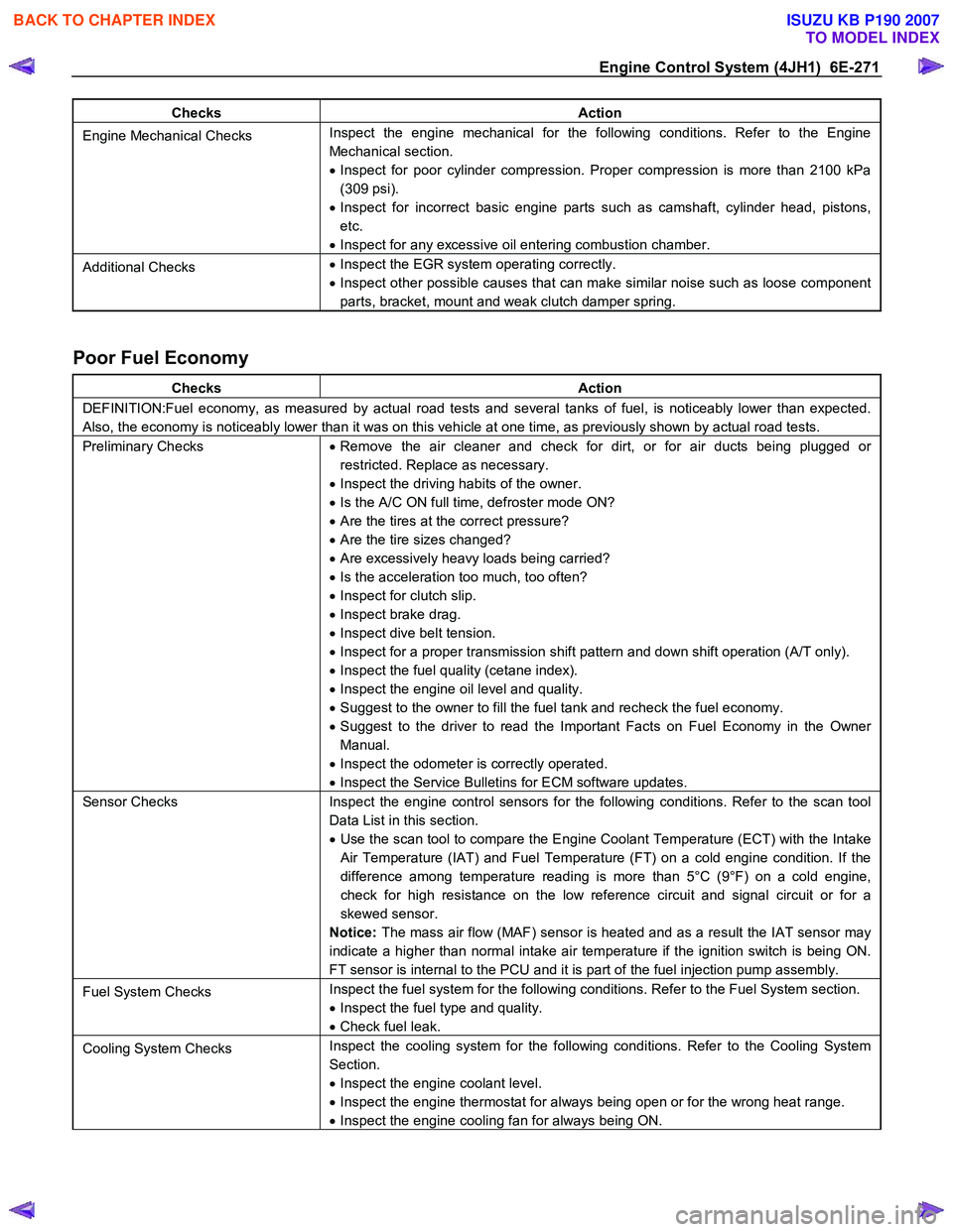
Checks Action
Engine Mechanical Checks Inspect the engine mechanical for the following conditions. Refer to the Engine
Mechanical section.
• Inspect for poor cylinder compression. Proper compression is more than 2100 kPa
(309 psi).
• Inspect for incorrect basic engine parts such as camshaft, cylinder head, pistons,
etc.
• Inspect for any excessive oil entering combustion chamber.
Additional Checks •
Inspect the EGR system operating correctly.
• Inspect other possible causes that can make similar noise such as loose component
parts, bracket, mount and weak clutch damper spring.
Poor Fuel Economy
Checks Action
DEFINITION:Fuel economy, as measured by actual road tests and several tanks of fuel, is noticeably lower than expected.
Also, the economy is noticeably lower than it was on this vehicle at one time, as previously shown by actual road tests.
Preliminary Checks • Remove the air cleaner and check for dirt, or for air ducts being plugged or
restricted. Replace as necessary.
• Inspect the driving habits of the owner.
• Is the A/C ON full time, defroster mode ON?
• Are the tires at the correct pressure?
• Are the tire sizes changed?
• Are excessively heavy loads being carried?
• Is the acceleration too much, too often?
• Inspect for clutch slip.
• Inspect brake drag.
• Inspect dive belt tension.
• Inspect for a proper transmission shift pattern and down shift operation (A/T only).
• Inspect the fuel quality (cetane index).
• Inspect the engine oil level and quality.
• Suggest to the owner to fill the fuel tank and recheck the fuel economy.
• Suggest to the driver to read the Important Facts on Fuel Economy in the Owner
Manual.
• Inspect the odometer is correctly operated.
• Inspect the Service Bulletins for ECM software updates.
Sensor Checks Inspect the engine control sensors for the following conditions. Refer to the scan tool
Data List in this section.
• Use the scan tool to compare the Engine Coolant Temperature (ECT) with the Intake
Air Temperature (IAT) and Fuel Temperature (FT) on a cold engine condition. If the
difference among temperature reading is more than 5°C (9°F) on a cold engine,
check for high resistance on the low reference circuit and signal circuit or for a
skewed sensor.
Notice: The mass air flow (MAF) sensor is heated and as a result the IAT sensor may
indicate a higher than normal intake air temperature if the ignition switch is being ON.
FT sensor is internal to the PCU and it is part of the fuel injection pump assembly.
Fuel System Checks Inspect the fuel system for the following conditions. Refer to the Fuel System section.
• Inspect the fuel type and quality.
• Check fuel leak.
Cooling System Checks Inspect the cooling system for the following conditions. Refer to the Cooling System
Section.
• Inspect the engine coolant level.
• Inspect the engine thermostat for always being open or for the wrong heat range.
• Inspect the engine cooling fan for always being ON.
BACK TO CHAPTER INDEX
TO MODEL INDEX
ISUZU KB P190 2007
Page 1311 of 6020
Engine Control System (4JH1) 6E-277
• DO NOT disturb the tool harnesses while
programming. If an interruption occurs during the
programming procedure, programming failure o
r
ECM damage may occur.
• If you are performing the Pass-Thru programming
procedure using a notebook computer without the
power cord, ensure that the internal battery is full
y
charged.
Service Programming System (SPS)
(Remote Procedure)
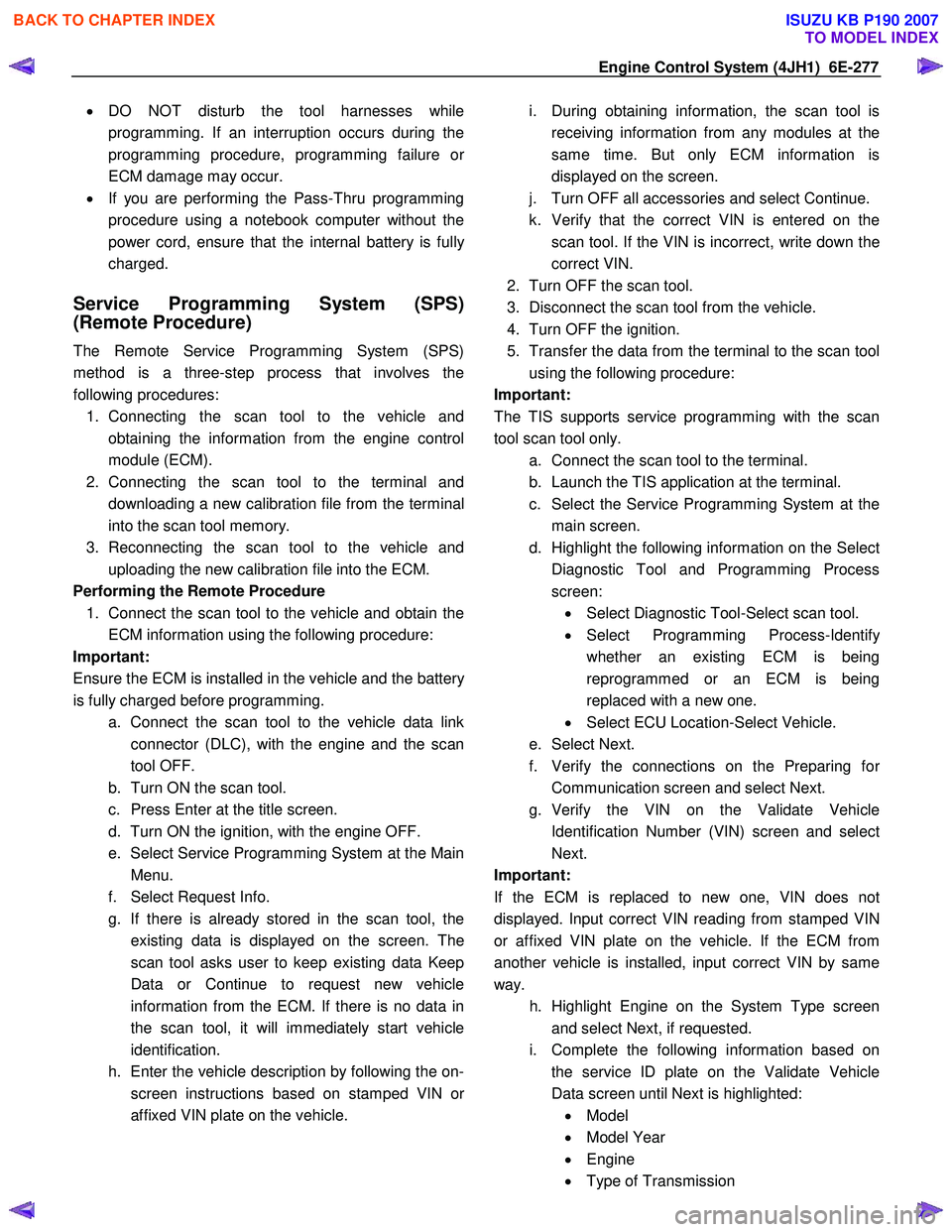
The Remote Service Programming System (SPS)
method is a three-step process that involves the
following procedures: 1. Connecting the scan tool to the vehicle and obtaining the information from the engine control
module (ECM).
2. Connecting the scan tool to the terminal and downloading a new calibration file from the terminal
into the scan tool memory.
3. Reconnecting the scan tool to the vehicle and uploading the new calibration file into the ECM.
Performing the Remote Procedure 1. Connect the scan tool to the vehicle and obtain the ECM information using the following procedure:
Important:
Ensure the ECM is installed in the vehicle and the batter
y
is fully charged before programming. a. Connect the scan tool to the vehicle data linkconnector (DLC), with the engine and the scan
tool OFF.
b. Turn ON the scan tool.
c. Press Enter at the title screen.
d. Turn ON the ignition, with the engine OFF.
e. Select Service Programming System at the Main Menu.
f. Select Request Info.
g. If there is already stored in the scan tool, the existing data is displayed on the screen. The
scan tool asks user to keep existing data Keep
Data or Continue to request new vehicle
information from the ECM. If there is no data in
the scan tool, it will immediately start vehicle
identification.
h. Enter the vehicle description by following the on- screen instructions based on stamped VIN o
r
affixed VIN plate on the vehicle.
i. During obtaining information, the scan tool is
receiving information from any modules at the
same time. But only ECM information is
displayed on the screen.
j. Turn OFF all accessories and select Continue.
k. Verify that the correct VIN is entered on the scan tool. If the VIN is incorrect, write down the
correct VIN.
2. Turn OFF the scan tool.
3. Disconnect the scan tool from the vehicle.
4. Turn OFF the ignition.
5. Transfer the data from the terminal to the scan tool using the following procedure:
Important:
The TIS supports service programming with the scan
tool scan tool only. a. Connect the scan tool to the terminal.
b. Launch the TIS application at the terminal.
c. Select the Service Programming System at the main screen.
d. Highlight the following information on the Selec
t
Diagnostic Tool and Programming Process
screen: • Select Diagnostic Tool-Select scan tool.
• Select Programming Process-Identif
y
whether an existing ECM is being
reprogrammed or an ECM is being
replaced with a new one.
• Select ECU Location-Select Vehicle.
e. Select Next.
f. Verify the connections on the Preparing fo
r
Communication screen and select Next.
g. Verify the VIN on the Validate Vehicle Identification Number (VIN) screen and selec
t
Next.
Important:
If the ECM is replaced to new one, VIN does no
t
displayed. Input correct VIN reading from stamped VIN
or affixed VIN plate on the vehicle. If the ECM from
another vehicle is installed, input correct VIN by same
way.
h. Highlight Engine on the System Type screen and select Next, if requested.
i. Complete the following information based on the service ID plate on the Validate Vehicle
Data screen until Next is highlighted: • Model
• Model Year
• Engine
• Type of Transmission
BACK TO CHAPTER INDEX
TO MODEL INDEX
ISUZU KB P190 2007
Page 1317 of 6020
Engine Control System (4JH1) 6E-283
Description And Operation
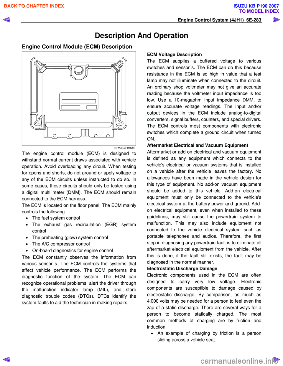
Engine Control Module (ECM) Description
RTW 66ESH001201
The engine control module (ECM) is designed to
withstand normal current draws associated with vehicle
operation. Avoid overloading any circuit. W hen testing
for opens and shorts, do not ground or apply voltage to
any of the ECM circuits unless instructed to do so. In
some cases, these circuits should only be tested using
a digital multi meter (DMM). The ECM should remain
connected to the ECM harness.
The ECM is located on the floor panel. The ECM mainl
y
controls the following.
• The fuel system control
• The exhaust gas recirculation (EGR) system
control
• The preheating (glow) system control
• The A/C compressor control
• On-board diagnostics for engine control
The ECM constantly observes the information from
various sensor s. The ECM controls the systems that
affect vehicle performance. The ECM performs the
diagnostic function of the system. The ECM can
recognize operational problems, alert the driver through
the malfunction indicator lamp (MIL), and store
diagnostic trouble codes (DTCs). DTCs identify the
system faults to aid the technician in making repairs.
ECM Voltage Description
The ECM supplies a buffered voltage to various
switches and sensor s. The ECM can do this because
resistance in the ECM is so high in value that a test
lamp may not illuminate when connected to the circuit.
An ordinary shop voltmeter may not give an accurate
reading because the voltmeter input impedance is too
low. Use a 10-megaohm input impedance DMM, to
ensure accurate voltage readings. The input and/o
r
output devices in the ECM include analog-to-digital
converters, signal buffers, counters, and special drivers.
The ECM controls most components with electronic
switches which complete a ground circuit when turned
ON.
Aftermarket Electrical and Vacuum Equipment
Aftermarket or add-on electrical and vacuum equipment
is defined as any equipment which connects to the
vehicle's electrical or vacuum systems that is installed
on a vehicle after the vehicle leaves the factory. No
allowances have been made in the vehicle design fo
r
this type of equipment. No add-on vacuum equipment
should be added to this vehicle. Add-on electrical
equipment must only be connected to the vehicle's
electrical system at the battery power and ground. Add-
on electrical equipment, even when installed to these
guidelines, may still cause the powertrain system to
malfunction. This may also include equipment not
connected to the vehicle electrical system such as
portable telephones and audios. Therefore, the first
step in diagnosing any powertrain fault is to eliminate all
aftermarket electrical equipment from the vehicle. Afte
r
this is done, if the fault still exists, the fault may be
diagnosed in the normal manner.
Electrostatic Discharge Damage
Electronic components used in the ECM are often
designed to carry very low voltage. Electronic
components are susceptible to damage caused b
y
electrostatic discharge. By comparison, as much as
4,000 volts may be needed for a person to feel even the
zap of a static discharge. There are several ways for a
person to become statically charged. The most
common methods of charging are by friction and
induction. •
An example of charging by friction is a person
sliding across a vehicle seat.
BACK TO CHAPTER INDEX
TO MODEL INDEX
ISUZU KB P190 2007
Page 1318 of 6020
6E-284 Engine Control System (4JH1)
Important:
To prevent possible electrostatic discharge damage,
follow these guidelines: • Do not touch the ECM connector pins or soldered
components on the ECM circuit board.
• Do not open the replacement part package until
the part is ready to be installed.
• Before removing the part from the package,
ground the package to a known good ground on
the vehicle.
• If the part has been handled while sliding across
the seat, while sitting down from a standing
position, or while walking a distance, touch a
known good ground before installing the part.
• Charge by induction occurs when a person with
well insulated shoes stands near a highly charged
object and momentarily touches ground. Charges
of the same polarity are drained off leaving the
person highly charged with opposite polarity.
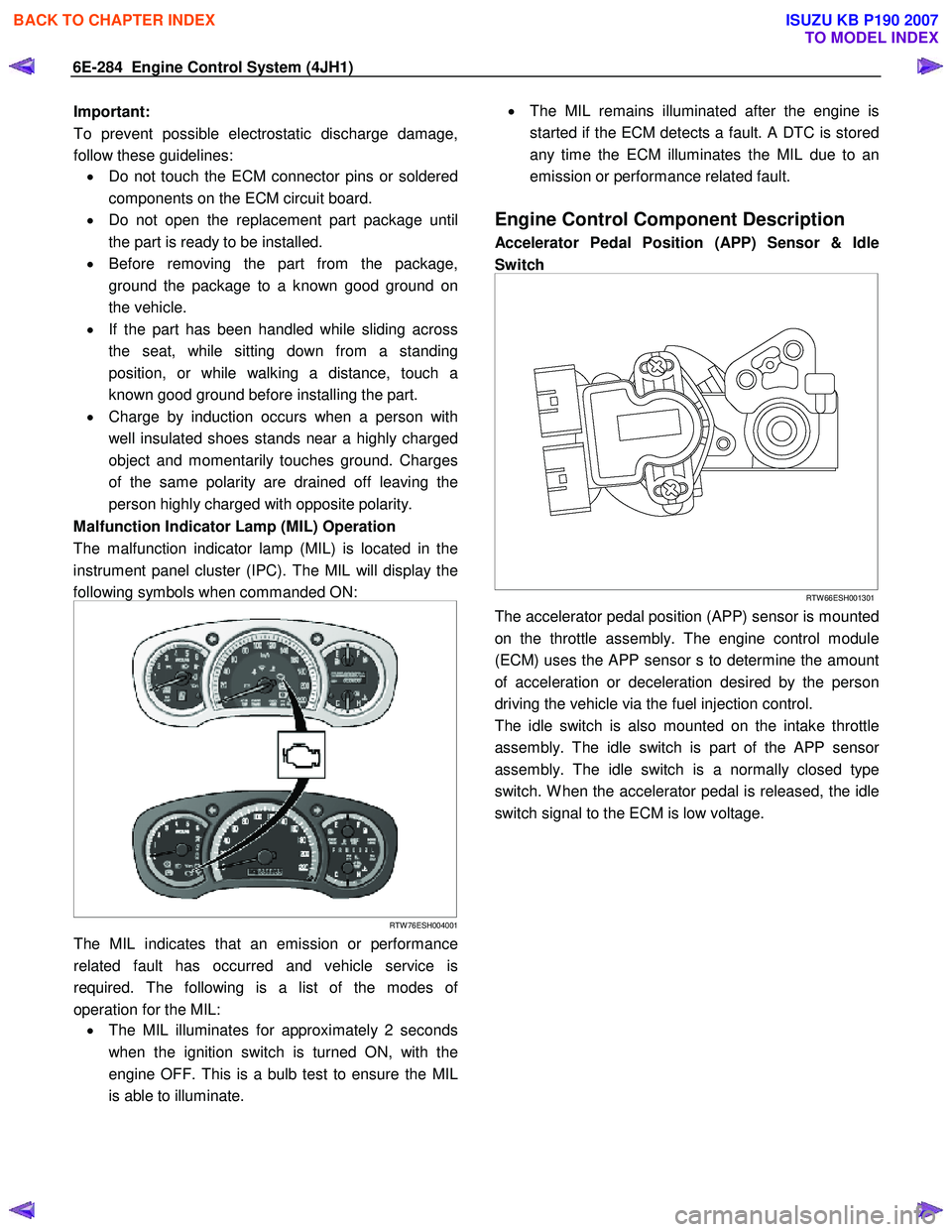
Malfunction Indicator Lamp (MIL) Operation
The malfunction indicator lamp (MIL) is located in the
instrument panel cluster (IPC). The MIL will display the
following symbols when commanded ON:
RTW 76ESH004001
The MIL indicates that an emission or performance
related fault has occurred and vehicle service is
required. The following is a list of the modes o
f
operation for the MIL: • The MIL illuminates for approximately 2 seconds
when the ignition switch is turned ON, with the
engine OFF. This is a bulb test to ensure the MIL
is able to illuminate.
•
The MIL remains illuminated after the engine is
started if the ECM detects a fault. A DTC is stored
any time the ECM illuminates the MIL due to an
emission or performance related fault.
Engine Control Component Description
Accelerator Pedal Position (APP) Sensor & Idle
Switch
RTW 66ESH001301
The accelerator pedal position (APP) sensor is mounted
on the throttle assembly. The engine control module
(ECM) uses the APP sensor s to determine the amount
of acceleration or deceleration desired by the person
driving the vehicle via the fuel injection control.
The idle switch is also mounted on the intake throttle
assembly. The idle switch is part of the APP senso
r
assembly. The idle switch is a normally closed type
switch. W hen the accelerator pedal is released, the idle
switch signal to the ECM is low voltage.
BACK TO CHAPTER INDEX
TO MODEL INDEX
ISUZU KB P190 2007
Page 1325 of 6020
Engine Control System (4JH1) 6E-291
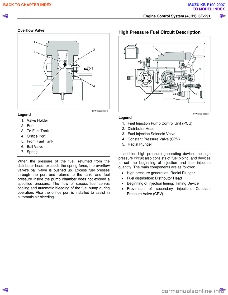
Overflow Valve
RTW 66ESH002401
Legend
1. Valve Holder
2. Port
3. To Fuel Tank
4. Orifice Port
5. From Fuel Tank
6. Ball Valve
7. Spring
W hen the pressure of the fuel, returned from the
distributor head, exceeds the spring force, the overflo
w
valve's ball valve is pushed up. Excess fuel presses
through the port and returns to the tank, and fuel
pressure inside the pump chamber does not exceed a
specified pressure. The flow of excess fuel serves
cooling and automatic bleeding of the fuel pump during
operation. Also the orifice port is installed to assist in
automatic air bleeding.
High Pressure Fuel Circuit Description
RTW 66ESH002501
Legend
1. Fuel Injection Pump Control Unit (PCU)
2. Distributor Head
3. Fuel Injection Solenoid Valve
4. Constant Pressure Valve (CPV)
5. Radial Plunger
In addition high pressure generating device, the high
pressure circuit also consists of fuel piping, and devices
to set the beginning of injection and fuel injection
quantity. The main components are as follows:
• High pressure generation: Radial Plunger
• Fuel distribution: Distributor Head
• Beginning of injection timing: Timing Device
• Prevention of secondary injection: Constant
Pressure Valve (CPV)
BACK TO CHAPTER INDEX
TO MODEL INDEX
ISUZU KB P190 2007
Page 1327 of 6020
Engine Control System (4JH1) 6E-293
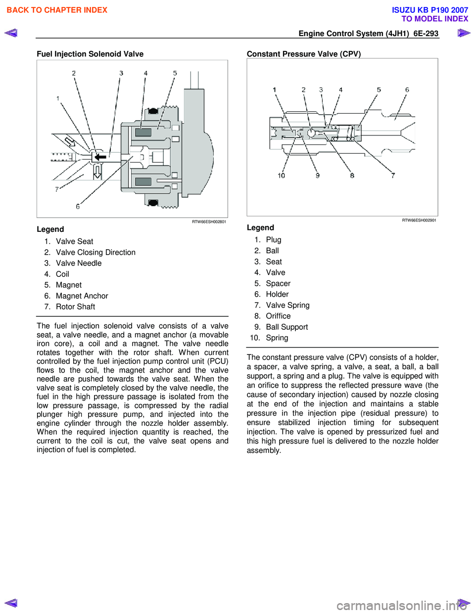
Fuel Injection Solenoid Valve
RTW 66ESH002801
Legend
1. Valve Seat
2. Valve Closing Direction
3. Valve Needle
4. Coil
5. Magnet
6. Magnet Anchor
7. Rotor Shaft
The fuel injection solenoid valve consists of a valve
seat, a valve needle, and a magnet anchor (a movable
iron core), a coil and a magnet. The valve needle
rotates together with the rotor shaft. W hen current
controlled by the fuel injection pump control unit (PCU)
flows to the coil, the magnet anchor and the valve
needle are pushed towards the valve seat. W hen the
valve seat is completely closed by the valve needle, the
fuel in the high pressure passage is isolated from the
low pressure passage, is compressed by the radial
plunger high pressure pump, and injected into the
engine cylinder through the nozzle holder assembly.
W hen the required injection quantity is reached, the
current to the coil is cut, the valve seat opens and
injection of fuel is completed.
Constant Pressure Valve (CPV)
RTW 66ESH002901
Legend
1. Plug
2. Ball
3. Seat
4. Valve
5. Spacer
6. Holder
7. Valve Spring
8. Oriffice
9. Ball Support
10. Spring
The constant pressure valve (CPV) consists of a holder,
a spacer, a valve spring, a valve, a seat, a ball, a ball
support, a spring and a plug. The valve is equipped with
an orifice to suppress the reflected pressure wave (the
cause of secondary injection) caused by nozzle closing
at the end of the injection and maintains a stable
pressure in the injection pipe (residual pressure) to
ensure stabilized injection timing for subsequent
injection. The valve is opened by pressurized fuel and
this high pressure fuel is delivered to the nozzle holde
r
assembly.
BACK TO CHAPTER INDEX
TO MODEL INDEX
ISUZU KB P190 2007
Page 1366 of 6020
6A-6 ENGINE MECHANICAL (4JK1/4JJ1)
• Insert a 0.15 mm (0.006 in) thickness gauge
between the roller of the rocker arm and the
camshaft to tighten up the adjusting screw o
f
the rocker arm. W hen the movement of the
thickness gauge becomes tight, fasten the
adjusting screw nut of the rocker arm.
Valve clearance mm (in)
Intake valve 0.15 (0.006)
Exhaust valve 0.15 (0.006)
Note:
Adjust while cold.
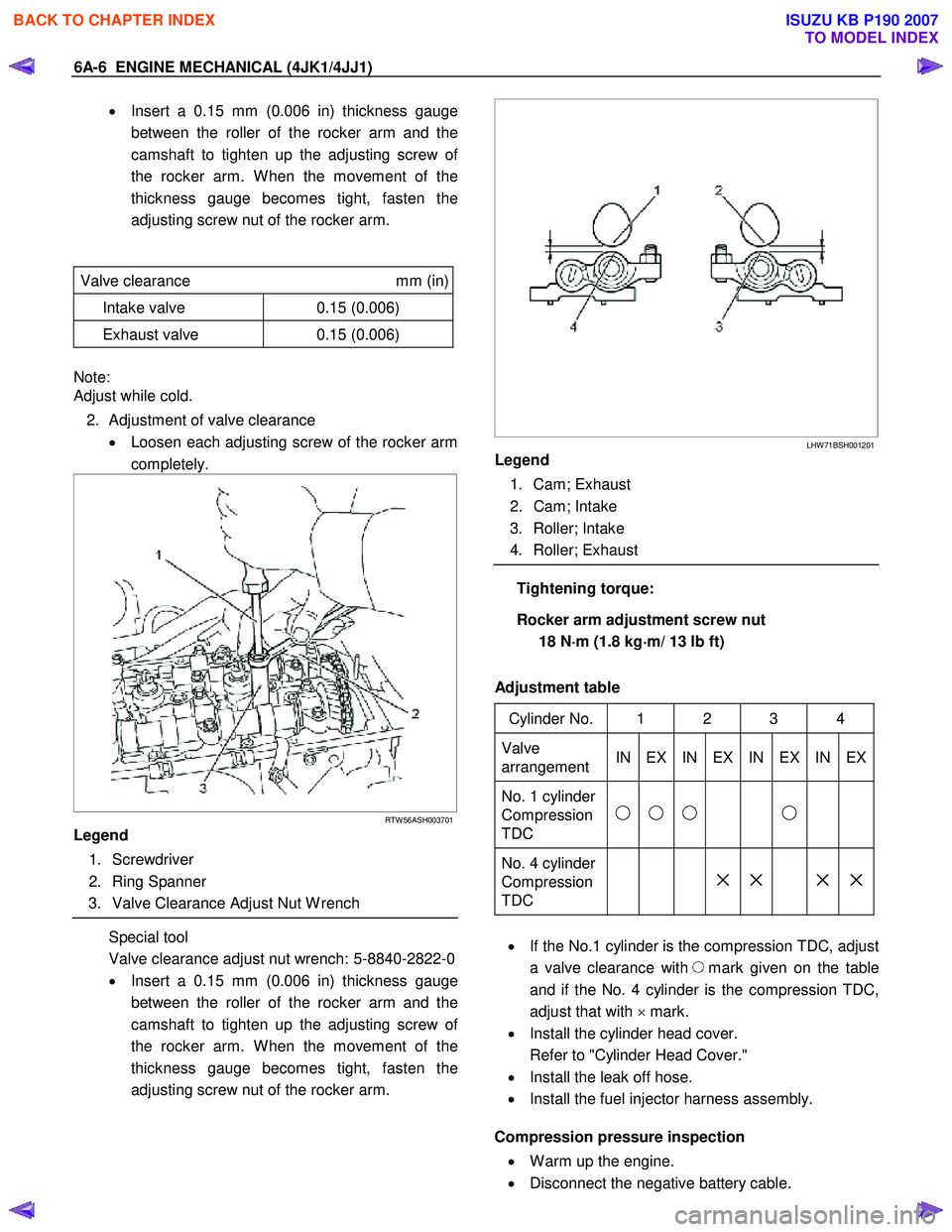
2. Adjustment of valve clearance • Loosen each adjusting screw of the rocker arm
completely.
RTW 56ASH003701
Legend
1. Screwdriver
2. Ring Spanner
3. Valve Clearance Adjust Nut W rench
Special tool
Valve clearance adjust nut wrench: 5-8840-2822-0
• Insert a 0.15 mm (0.006 in) thickness gauge
between the roller of the rocker arm and the
camshaft to tighten up the adjusting screw o
f
the rocker arm. W hen the movement of the
thickness gauge becomes tight, fasten the
adjusting screw nut of the rocker arm.
LHW 71BSH001201
Legend
1. Cam; Exhaust
2. Cam; Intake
3. Roller; Intake
4. Roller; Exhaust
Tightening torque:
Rocker arm adjustment screw nut 18 N ⋅
⋅⋅
⋅
m (1.8 kg ⋅
⋅⋅
⋅
m/ 13 lb ft)
Adjustment table
Cylinder No. 1 2 3 4
Valve
arrangement IN EX IN EX IN EX IN EX
No. 1 cylinder
Compression
TDC
No. 4 cylinder
Compression
TDC
× × × ×
• If the No.1 cylinder is the compression TDC, adjust
a valve clearance with
mark given on the table
and if the No. 4 cylinder is the compression TDC,
adjust that with × mark.
• Install the cylinder head cover.
Refer to "Cylinder Head Cover."
• Install the leak off hose.
• Install the fuel injector harness assembly.
Compression pressure inspection
• W arm up the engine.
• Disconnect the negative battery cable.
BACK TO CHAPTER INDEX
TO MODEL INDEX
ISUZU KB P190 2007
Page 1367 of 6020
ENGINE MECHANICAL (4JK1/4JJ1) 6A-7
• Remove the all glow plugs.
Note:
W hen the harness connector is removed, ECM judges
that it broke down and DTC is recorded. Upon
completion of measurement, never fail to clear the
memory of the ECM.
(For how to clear the memory of the ECM, refer to
“ENGINE CONTROL SYSTEM” Section)
• Connect the negative battery cable.
• Turn on the starter to emit foreign matter within the
cylinders.
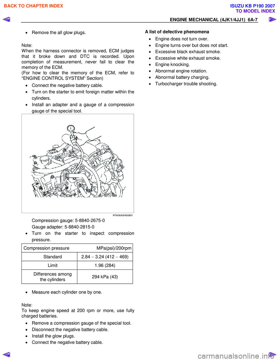
• Install an adapter and a gauge of a compression
gauge of the special tool.
RTW 56ASH003801
Compression gauge: 5-8840-2675-0
Gauge adapter: 5-8840-2815-0
• Turn on the starter to inspect compression
pressure.
Compression pressure MPa(psi)/200rpm
Standard 2.84 − 3.24 (412 − 469)
Limit 1.96 (284)
Differences among
the cylinders 294 kPa (43)
•
Measure each cylinder one by one.
Note:
To keep engine speed at 200 rpm or more, use full
y
charged batteries.
• Remove a compression gauge of the special tool.
• Disconnect the negative battery cable.
• Install the glow plugs.
• Connect the negative battery cable.
A list of defective phenomena
• Engine does not turn over.
• Engine turns over but does not start.
• Excessive black exhaust smoke.
• Excessive white exhaust smoke.
• Engine knocking.
• Abnormal engine rotation.
• Abnormal battery charging.
• Turbocharger trouble shooting.
BACK TO CHAPTER INDEX
TO MODEL INDEX
ISUZU KB P190 2007