Page 3669 of 6020
Powertrain Interface Module – V6 Page 6E1–8
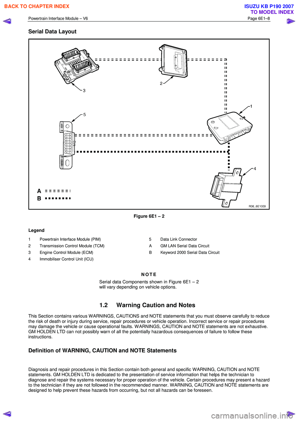
Serial Data Layout
Figure 6E1 – 2
Legend
1 Powertrain Interface Module (PIM)
2 Transmission Control Module (TCM)
3 Engine Control Module (ECM)
4 Immobiliser Control Unit (ICU)
5 Data Link Connector
A GM LAN Serial Data Circuit
B Keyword 2000 Serial Data Circuit
NOTE
Serial data Components shown in Figure 6E1 – 2
will vary depending on vehicle options.
1.2 Warning Caution and Notes
This Section contains various W ARNINGS, CAUTIONS and NOTE statements that you must observe carefully to reduce
the risk of death or injury during service, repair procedures or vehicle operation. Incorrect service or repair procedures
may damage the vehicle or cause operational faults. W ARNINGS, CAUTION and NOTE statements are not exhaustive.
GM HOLDEN LTD can not possibly warn of all the potentially hazardous consequences of failure to follow these
instructions.
Definition of WARNING, CAUTION and NOTE Statements
Diagnosis and repair procedures in this Section contain both general and specific W ARNING, CAUTION and NOTE
statements. GM HOLDEN LTD is dedicated to the presentation of service information that helps the technician to
diagnose and repair the systems necessary for proper operation of the vehicle. Certain procedures may present a hazard
to the technician if they are not followed in the recommended manner. W ARNING, CAUTION and NOTE statements are
designed to help prevent these hazards from occurring, but not all hazards can be foreseen.
BACK TO CHAPTER INDEX
TO MODEL INDEX
ISUZU KB P190 2007
Page 3671 of 6020
Powertrain Interface Module – V6 Page 6E1–10
2 Component Location
2.1 Engine Compartment
Figure 6E1 – 3
Legend
1 Engine Control Module (ECM) 2 Vehicle Acceleration Sensor
BACK TO CHAPTER INDEX
TO MODEL INDEX
ISUZU KB P190 2007
Page 3673 of 6020
Powertrain Interface Module – V6 Page 6E1–12
3 Component Description and
Operation
3.1 Powertrain Interface Module
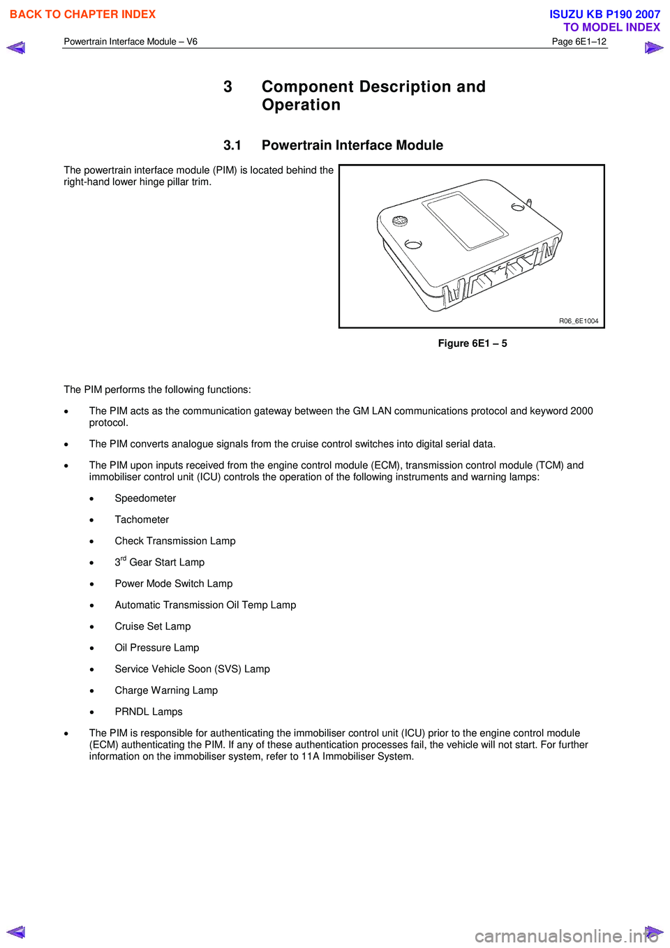
The powertrain interface module (PIM) is located behind the
right-hand lower hinge pillar trim.
Figure 6E1 – 5
The PIM performs the following functions:
• The PIM acts as the communication gateway between the GM LAN communications protocol and keyword 2000
protocol.
• The PIM converts analogue signals from the cruise control switches into digital serial data.
• The PIM upon inputs received from the engine control module (ECM), transmission control module (TCM) and
immobiliser control unit (ICU) controls the operation of the following instruments and warning lamps:
• Speedometer
• Tachometer
• Check Transmission Lamp
• 3
rd Gear Start Lamp
• Power Mode Switch Lamp
• Automatic Transmission Oil Temp Lamp
• Cruise Set Lamp
• Oil Pressure Lamp
• Service Vehicle Soon (SVS) Lamp
• Charge W arning Lamp
• PRNDL Lamps
• The PIM is responsible for authenticating the immobiliser control unit (ICU) prior to the engine control module
(ECM) authenticating the PIM. If any of these authentication processes fail, the vehicle will not start. For further
information on the immobiliser system, refer to 11A Immobiliser System.
BACK TO CHAPTER INDEX
TO MODEL INDEX
ISUZU KB P190 2007
Page 3674 of 6020
Powertrain Interface Module – V6 Page 6E1–13
3.2 Powertrain Interface Module Gateway
Components
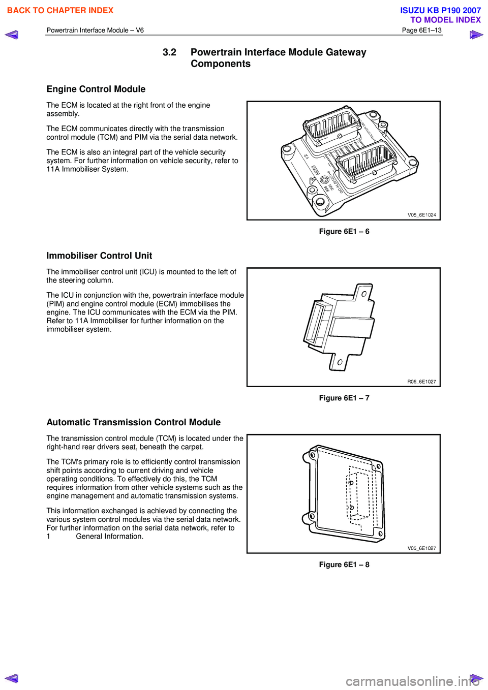
Engine Control Module
The ECM is located at the right front of the engine
assembly.
The ECM communicates directly with the transmission
control module (TCM) and PIM via the serial data network.
The ECM is also an integral part of the vehicle security
system. For further information on vehicle security, refer to
11A Immobiliser System.
Figure 6E1 – 6
Immobiliser Control Unit
The immobiliser control unit (ICU) is mounted to the left of
the steering column.
The ICU in conjunction with the, powertrain interface module
(PIM) and engine control module (ECM) immobilises the
engine. The ICU communicates with the ECM via the PIM.
Refer to 11A Immobiliser for further information on the
immobiliser system.
Figure 6E1 – 7
Automatic Transmission Control Module
The transmission control module (TCM) is located under the
right-hand rear drivers seat, beneath the carpet.
The TCM's primary role is to efficiently control transmission
shift points according to current driving and vehicle
operating conditions. To effectively do this, the TCM
requires information from other vehicle systems such as the
engine management and automatic transmission systems.
This information exchanged is achieved by connecting the
various system control modules via the serial data network.
For further information on the serial data network, refer to
1 General Information.
Figure 6E1 – 8
BACK TO CHAPTER INDEX
TO MODEL INDEX
ISUZU KB P190 2007
Page 3682 of 6020
Powertrain Interface Module – V6 Page 6E1–21
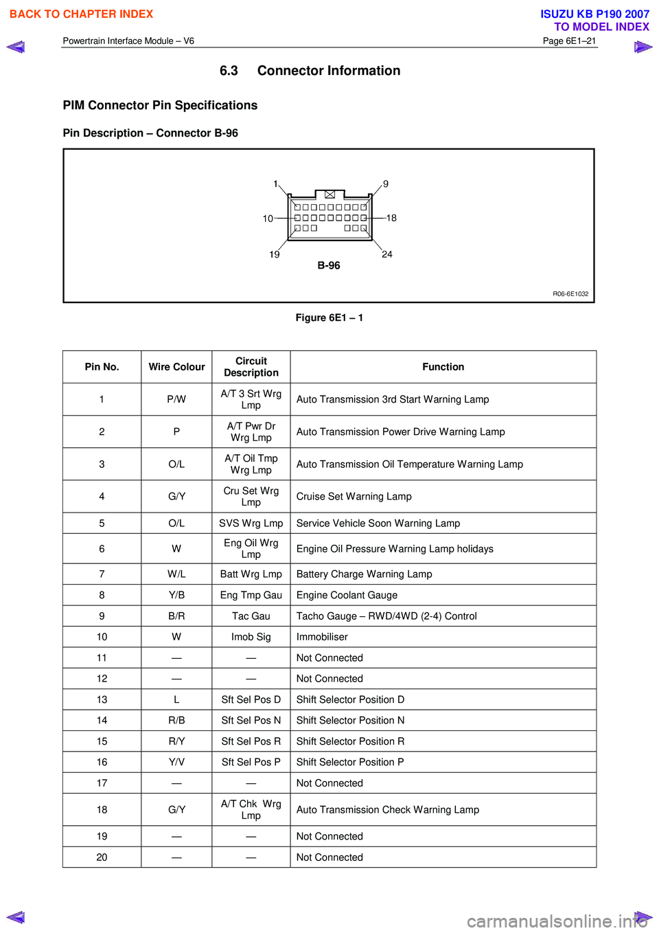
6.3 Connector Information
PIM Connector Pin Specifications
Pin Description – Connector B-96
Figure 6E1 – 1
Pin No. Wire Colour Circuit
Description Function
1 P/W
A/T 3 Srt W rg
Lmp Auto Transmission 3rd Start W arning Lamp
2 P
A/T Pwr Dr
W rg Lmp Auto Transmission Power Drive W arning Lamp
3 O/L A/T Oil Tmp
W rg Lmp Auto Transmission Oil Temperature W arning Lamp
4 G/Y
Cru Set W rg
Lmp Cruise Set W arning Lamp
5
O/L SVS W rg Lmp Service Vehicle Soon W arning Lamp
6 W Eng Oil W rg
Lmp Engine Oil Pressure W arning Lamp holidays
7
W /L Batt W rg Lmp Battery Charge W arning Lamp
8 Y/B Eng Tmp Gau Engine Coolant Gauge
9 B/R Tac Gau Tacho Gauge – RW D/4W D (2-4) Control
10 W Imob Sig Immobiliser
11 — — Not Connected
12 — — Not Connected
13 L Sft Sel Pos D Shift Selector Position D
14 R/B Sft Sel Pos N Shift Selector Position N
15 R/Y Sft Sel Pos R Shift Selector Position R
16 Y/V Sft Sel Pos P Shift Selector Position P
17 — — Not Connected
18 G/Y A/T Chk W rg
Lmp Auto Transmission Check W arning Lamp
19 — — Not
Connected
20 — — Not Connected
BACK TO CHAPTER INDEX
TO MODEL INDEX
ISUZU KB P190 2007
Page 3684 of 6020
Powertrain Interface Module – V6 Page 6E1–23
Pin No. Wire Colour Circuit
Description Function
20 P/L
Cru Cont Sw
Pwr ON Cruise Control Switch Power ON
21 BR/R Batt Battery
Supply
22 B Grd Ground Engine Bay – L/H
23 — — Not Connected
24 G/Y A/T Pwr Dr Sw Auto Transmission Power Drive
BACK TO CHAPTER INDEX
TO MODEL INDEX
ISUZU KB P190 2007
Page 3685 of 6020
Powertrain Interface Module – V6 Page 6E1–24
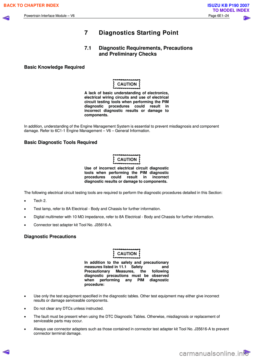
7 Diagnostics Starting Point
7.1 Diagnostic Requirements, Precautions
and Preliminary Checks
Basic Knowledge Required
A lack of basic understanding of electronics,
electrical wiring circuits and use of electrical
circuit testing tools when performing the PIM
diagnostic procedures could result in
incorrect diagnostic results or damage to
components.
In addition, understanding of the Engine Management System is essential to prevent misdiagnosis and component
damage. Refer to 6C1-1 Engine Management – V6 – General Information.
Basic Diagnostic Tools Required
Use of incorrect electrical circuit diagnostic
tools when performing the PIM diagnostic
procedures could result in incorrect
diagnostic results or damage to components.
The following electrical circuit testing tools are required to perform the diagnostic procedures detailed in this Section:
• Tech 2.
• Test lamp, refer to 8A Electrical - Body and Chassis for further information.
• Digital multimeter with 10 M Ω impedance, refer to 8A Electrical - Body and Chassis for further information.
• Connector test adapter kit Tool No. J35616-A.
Diagnostic Precautions
In addition to the safety and precautionary
measures listed in 11.1 Safety and
Precautionary Measures, the following
diagnostic precautions must be observed
when performing any PIM diagnostic
procedure:
• Use only the test equipment specified in the diagnostic tables. Other test equipment may either give incorrect
results or damage serviceable components.
• Do not clear any DTCs unless instructed.
• The fault must be present when using the DTC Diagnostic Tables. Otherwise, misdiagnosis or replacement of
serviceable parts may occur.
• Always use connector adapters such as those contained in connector test adapter kit Tool No. J35616-A to prevent
connector terminal damage.
BACK TO CHAPTER INDEX
TO MODEL INDEX
ISUZU KB P190 2007
Page 3687 of 6020
Powertrain Interface Module – V6 Page 6E1–26
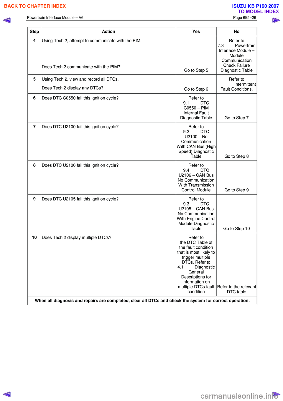
Step Action Yes No
4
Using Tech 2, attempt to communicate with the PIM.
Does Tech 2 communicate with the PIM? Go to Step 5 Refer to
7.3 Powertrain Interface Module –
Module
Communication Check Failure
Diagnostic Table
5 Using Tech 2, view and record all DTCs.
Does Tech 2 display any DTCs? Go to Step 6 Refer to
Intermittent Fault Conditions.
6 Does DTC C0550 fail this ignition cycle? Refer to
9.1 DTC
C0550 – PIM
Internal Fault
Diagnostic Table Go to Step 7
7 Does DTC U2100 fail this ignition cycle? Refer to
9.2 DTC
U2100 – No
Communication
W ith CAN Bus (High Speed) Diagnostic
Table Go to Step 8
8 Does DTC U2106 fail this ignition cycle? Refer to
9.4 DTC
U2106 – CAN Bus
No Communication
W ith Transmission Control Module Go to Step 9
9
Does DTC U2105 fail this ignition cycle? Refer to
9.3 DTC
U2105 – CAN Bus
No Communication
W ith Engine Control Module Diagnostic
Table Go to Step 10
10 Does Tech 2 display multiple DTCs? Refer to
the DTC Table of
the fault condition
that is most likely to
trigger multiple
DTCs. Refer to
4.1 Diagnostic General
Descriptions for information on
multiple DTCs fault condition Refer to the relevant
DTC table
When all diagnosis and repairs are completed, clear all DTCs and check the system for correct operation.
BACK TO CHAPTER INDEX
TO MODEL INDEX
ISUZU KB P190 2007