2007 ISUZU KB P190 Engine
[x] Cancel search: EnginePage 3626 of 6020
Starting System – V6 Page 6D1-2–18
Cranking Voltage Test
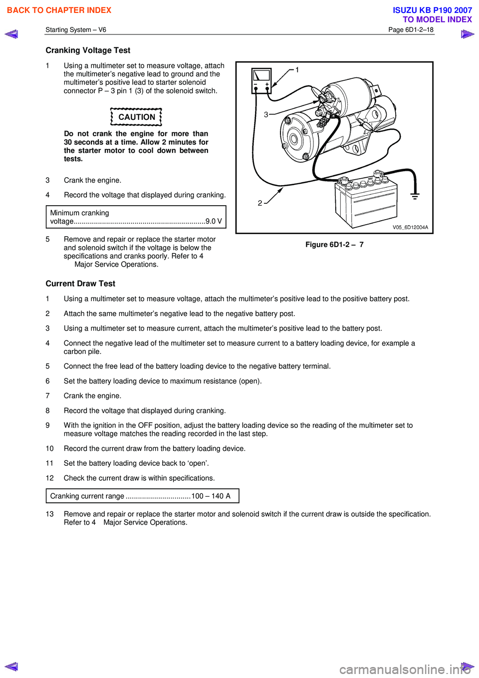
1 Using a multimeter set to measure voltage, attach
the multimeter’s negative lead to ground and the
multimeter’s positive lead to starter solenoid
connector P – 3 pin 1 (3) of the solenoid switch.
Do not crank the engine for more than
30 seconds at a time. Allow 2 minutes for
the starter motor to cool down between
tests.
3 Crank the engine.
4 Record the voltage that displayed during cranking.
Minimum cranking
voltage.................................................................9.0 V
5 Remove and repair or replace the starter motor and solenoid switch if the voltage is below the
specifications and cranks poorly. Refer to 4
Major Service Operations. Figure 6D1-2 – 7
Current Draw Test
1 Using a multimeter set to measure voltage, attach the multimeter’s positive lead to the positive battery post.
2 Attach the same multimeter’s negative lead to the negative battery post.
3 Using a multimeter set to measure current, attach the multimeter’s positive lead to the battery post.
4 Connect the negative lead of the multimeter set to measure current to a battery loading device, for example a carbon pile.
5 Connect the free lead of the battery loading device to the negative battery terminal.
6 Set the battery loading device to maximum resistance (open).
7 Crank the engine.
8 Record the voltage that displayed during cranking.
9 W ith the ignition in the OFF position, adjust the battery loading device so the reading of the multimeter set to measure voltage matches the reading recorded in the last step.
10 Record the current draw from the battery loading device.
11 Set the battery loading device back to ‘open’.
12 Check the current draw is within specifications.
Cranking current range ................................ 100 – 140 A
13 Remove and repair or replace the starter motor and solenoid switch if the current draw is outside the specification. Refer to 4 Major Service Operations.
BACK TO CHAPTER INDEX
TO MODEL INDEX
ISUZU KB P190 2007
Page 3627 of 6020
Starting System – V6 Page 6D1-2–19
4 Major Service Operations
Disconnection of the battery affects certain
vehicle electronic systems. Refer to 00
Warnings, Cautions and Notes before
disconnecting the battery.
4.1 Starter Motor
Remove
The starter motor is in close proximity to the
left-hand side exhaust manifold and engine
pipe. Allow the engine to cool before
attempting to remove the starter motor.
1 Refer to 1.1 W ARNING, CAUTION and NOTES in this Service Information before disconnecting the battery.
2 Disconnect the battery ground lead.
3 Raise the front of the vehicle. For jacking locations, refer to 0A General Information.
4 Put safety stands in place.
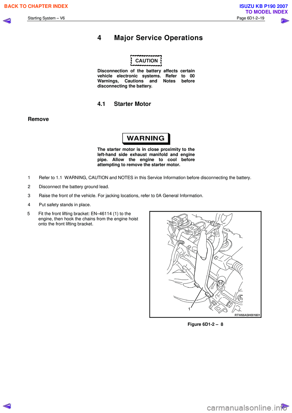
5 Fit the front lifting bracket: EN–46114 (1) to the engine, then hook the chains from the engine hoist
onto the front lifting bracket.
Figure 6D1-2 – 8
BACK TO CHAPTER INDEX
TO MODEL INDEX
ISUZU KB P190 2007
Page 3628 of 6020
Starting System – V6 Page 6D1-2–20
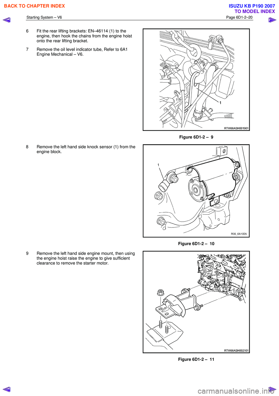
6 Fit the rear lifting brackets: EN–46114 (1) to the
engine, then hook the chains from the engine hoist
onto the rear lifting bracket.
7 Remove the oil level indicator tube, Refer to 6A1 Engine Mechanical – V6.
Figure 6D1-2 – 9
8 Remove the left hand side knock sensor (1) from the engine block.
Figure 6D1-2 – 10
9 Remove the left hand side engine mount, then using the engine hoist raise the engine to give sufficient
clearance to remove the starter motor.
Figure 6D1-2 – 11
BACK TO CHAPTER INDEX
TO MODEL INDEX
ISUZU KB P190 2007
Page 3629 of 6020
Starting System – V6 Page 6D1-2–21
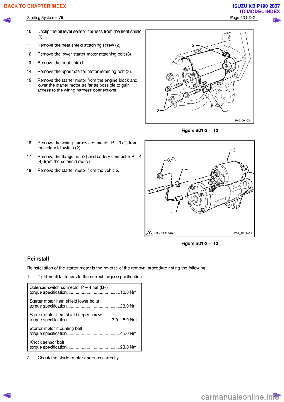
10 Unclip the oil level sensor harness from the heat shield
(1).
11 Remove the heat shield attaching screw (2).
12 Remove the lower starter motor attaching bolt (3).
13 Remove the heat shield.
14 Remove the upper starter motor retaining bolt (3).
15 Remove the starter motor from the engine block and lower the starter motor as far as possible to gain
access to the wiring harness connections.
Figure 6D1-2 – 12
16 Remove the wiring harness connector P – 3 (1) from the solenoid switch (2).
17 Remove the flange nut (3) and battery connector P – 4 (4) from the solenoid switch.
18 Remove the starter motor from the vehicle.
Figure 6D1-2 – 13
Reinstall
Reinstallation of the starter motor is the reverse of the removal procedure noting the following:
1 Tighten all fasteners to the correct torque specification.
Solenoid switch connector P – 4 nut (B+)
torque specification ............................................10.0 Nm
Starter motor heat shield lower bolts
torque specification ............................................23.0 Nm
Starter motor heat shield upper screw
torque specification .....................................3.0 – 5.0 Nm
Starter motor mounting bolt
torque specification ............................................45.0 Nm
Knock sensor bolt
torque specification ............................................23.0 Nm
2 Check the starter motor operates correctly.
BACK TO CHAPTER INDEX
TO MODEL INDEX
ISUZU KB P190 2007
Page 3640 of 6020
Starting System – V6 Page 6D1-2–32
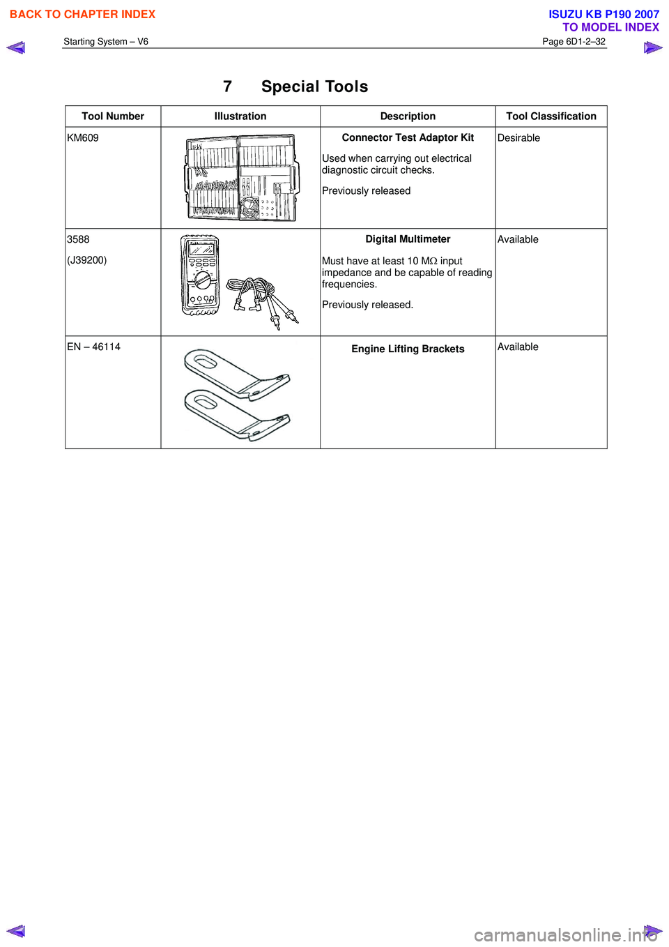
7 Special Tools
Tool Number Illustration Description Tool Classification
KM609
Connector Test Adaptor Kit
Used when carrying out electrical
diagnostic circuit checks.
Previously released
Desirable
3588
(J39200)
Digital Multimeter
Must have at least 10 M Ω input
impedance and be capable of reading
frequencies.
Previously released.
Available
EN – 46114 Engine Lifting Brackets
Available
BACK TO CHAPTER INDEX
TO MODEL INDEX
ISUZU KB P190 2007
Page 3643 of 6020
Battery Page 6D1-3–3
1 General Information
The vehicle is fitted with a 12 V battery located in the front right-hand corner of the engine compartment. The battery
provides:
• power for cranking the engine,
• power for a limited time when the electrical load exceeds the generator output,
• power for the accessories when the engine is not running, and
• a voltage stabilising load for the electrical system.
1.1 WARNING, CAUTION and NOTES
This Section contains various W ARNINGS, CAUTIONS and NOTE statements that you must observe carefully to reduce
the risk of death or injury during service, repair procedures or vehicle operation. Incorrect service or repair procedures
may damage the vehicle or cause operational faults. W ARNINGS, CAUTION and NOTE statements are not exhaustive.
HOLDEN LTD can not possibly warn of all the potentially hazardous consequences of failure to follow these instructions.
Definition of WARNING, CAUTION and NOTE Statements
Diagnosis and repair procedures in this Section contain both general and specific W ARNING, CAUTION and NOTE
statements. HOLDEN LTD is dedicated to the presentation of service information that helps the technician to diagnose
and repair the systems necessary for proper operation of the vehicle. Certain procedures may present a hazard to the
technician if they are not followed in the recommended manner. W ARNING, CAUTION and NOTE statements are
designed to help prevent these hazards from occurring, but not all hazards can be foreseen.
WARNING defined
A W ARNING statement immediately precedes an operating procedure or maintenance practice which, if not correctly
followed, could result in death or injury. A W ARNING statement alerts you to take necessary action or not to take a
prohibited action. If a W ARNING statement is ignored, the following consequences may occur:
• Death or injury to the technician or other personnel working on the vehicle,
• Death or injury to other people in or near the workplace area, and / or
• Death or injury to the driver / or passenger(s) of the vehicle or other people, if the vehicle has been improperly
repaired.
CAUTION defined
A CAUTION statement immediately precedes an operating procedure or maintenance practice which, if not correctly
followed, could result in damage to or destruction of equipment, or corruption of data. If a CAUTION statement is ignored,
the following consequences may occur:
• Damage to the vehicle,
• Unnecessary vehicle repairs or component replacement,
• Faulty operation or performance of any system or component being repaired,
• Damage to any system or components which depend on the proper operation of the system or component being
repaired,
• Faulty operation or performance of any systems or components which depend on the proper operation or
performance of the system or component under repair,
• Damage to fasteners, basic tools or special tools and / or
• Leakage of coolant, lubricant or other vital fluids.
NOTE defined
A NOTE statement immediately precedes or follows an operating procedure, maintenance practice or condition that
requires highlighting. A NOTE statement also emphasises necessary characteristics of a diagnostic or repair procedure.
A NOTE statement is designed to:
BACK TO CHAPTER INDEX
TO MODEL INDEX
ISUZU KB P190 2007
Page 3645 of 6020
Battery Page 6D1-3–5
This time is measured as the time taken for the battery voltage to reduce to 10.5 V from the following initial conditions:
• a fully charged battery at 25 °C, and
• discharged at a constant current of 25 A.
Cold Cranking Amps
The CCA rating indicates the ability of the battery to maintain enough voltage for ignition requirements while supplying
engine cranking current for long enough to start the engine under severely cold conditions.
The rating is the minimum amperage maintained when the engine is cranked for 30 seconds. The battery must maintain
at least 7.2 V at 18 °C.
Ratings
A specification label on the top of the battery displays the original equipment part number.
All vehicles are fitted with a low maintenance, 85 minute RC and 430 CCA battery.
BACK TO CHAPTER INDEX
TO MODEL INDEX
ISUZU KB P190 2007
Page 3647 of 6020
Battery Page 6D1-3–7
3 Diagnosis
3.1 Diagnostic Procedures
Introduction
This test is used to aid in diagnosing faults with the vehicle where the battery seems to be at fault.
W ith the increased use of electronic sensors and computer control, the battery is much more than just a component used
to start a car. Low battery voltage can:
• affect the operation of the vehicle control modules and cause driveability problems, and
• cause the control modules to set diagnostic trouble codes (DTCs).
For example if a control module senses low battery voltage, it may increase fuel injector timing to increase engine rpm to
increase the generator output.
Therefore consider the state of charge of the battery any time a customer complains of a driveability related problem.
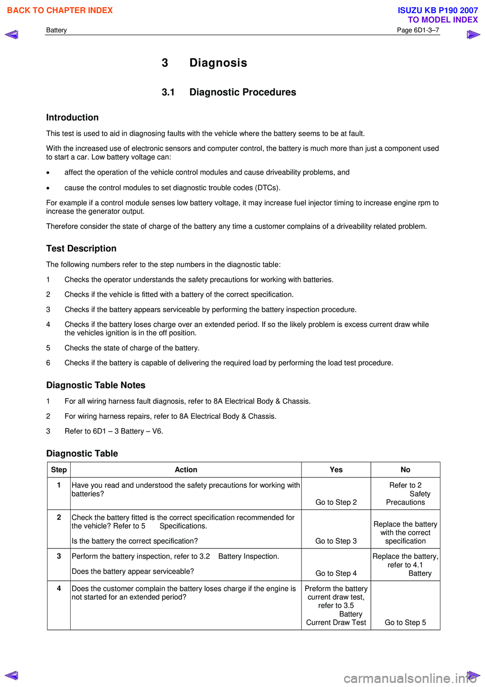
Test Description
The following numbers refer to the step numbers in the diagnostic table:
1 Checks the operator understands the safety precautions for working with batteries.
2 Checks if the vehicle is fitted with a battery of the correct specification.
3 Checks if the battery appears serviceable by performing the battery inspection procedure.
4 Checks if the battery loses charge over an extended period. If so the likely problem is excess current draw while the vehicles ignition is in the off position.
5 Checks the state of charge of the battery.
6 Checks if the battery is capable of delivering the required load by performing the load test procedure.
Diagnostic Table Notes
1 For all wiring harness fault diagnosis, refer to 8A Electrical Body & Chassis.
2 For wiring harness repairs, refer to 8A Electrical Body & Chassis.
3 Refer to 6D1 – 3 Battery – V6.
Diagnostic Table
Step Action Yes No
1
Have you read and understood the safety precautions for working with
batteries? Go to Step 2 Refer to 2
Safety Precautions
2 Check the battery fitted is the correct specification recommended for
the vehicle? Refer to 5 Specifications.
Is the battery the correct specification? Go to Step 3 Replace the battery
with the correct
specification
3 Perform the battery inspection, refer to 3.2 Battery Inspection.
Does the battery appear serviceable? Go to Step 4 Replace the battery,
refer to 4.1
Battery
4 Does the customer complain the battery loses charge if the engine is
not started for an extended period? Preform the battery
current draw test, refer to 3.5
Battery
Current Draw Test Go to Step 5
BACK TO CHAPTER INDEX
TO MODEL INDEX
ISUZU KB P190 2007