Page 2962 of 6020
Engine Mechanical – V6 Page 6A1–185
Page 6A1–185
Reassemble
CAUTION
As there are no serviceable components
within the oil pump, a disassembled oil pump
must be replaced.
Reinstall
1 Align the oil pump gerotor with the crankshaft flats
and fit the oil pump assembly to the engine block.
2 Align the pump body (2) with the mounting holes in the cylinder block.
3 Install the oil pump bolt (1), three places, and tighten to the correct torque specification.
4 Install the primary timing chain, refer to 3.16 Timing
Chains, Tensioners, Shoes and Guides .
Oil pump attaching bolt torque
specificat ion ............................................ 20.0 – 26.0 Nm
Figure 6A1 – 297
BACK TO CHAPTER INDEX
TO MODEL INDEX
ISUZU KB P190 2007
Page 2985 of 6020
Engine Mechanical – V6 Page 6A1–208
Page 6A1–208
2 Apply a liberal amount of engine oil to the
camshaft (1) journals and the right-hand cylinder
head camshaft carriers (2).
Figure 6A1 – 345
3 Position the camshafts (1) on the cylinder head and assemble the camshaft spro ckets to the camshafts.
NOTE
Install the camshaft sprocket bolts but do not
tighten at this stage.
Figure 6A1 – 346
4 Ensure the camshaft lobes are in the neutral position with the flats on the back of the camshafts up and
parallel (1) with the right-hand cylinder head camshaft
cover rail.
5 Ensure the marks on the right-hand exhaust camshaft position actuator and timing chain, made prior to the
disassemble operation are aligned.
6 Ensure the marks on the right-hand intake camshaft position actuator and timing chain, made prior to the
disassemble operation are aligned.
Figure 6A1 – 347
BACK TO CHAPTER INDEX
TO MODEL INDEX
ISUZU KB P190 2007
Page 2986 of 6020

Engine Mechanical – V6 Page 6A1–209
Page 6A1–209
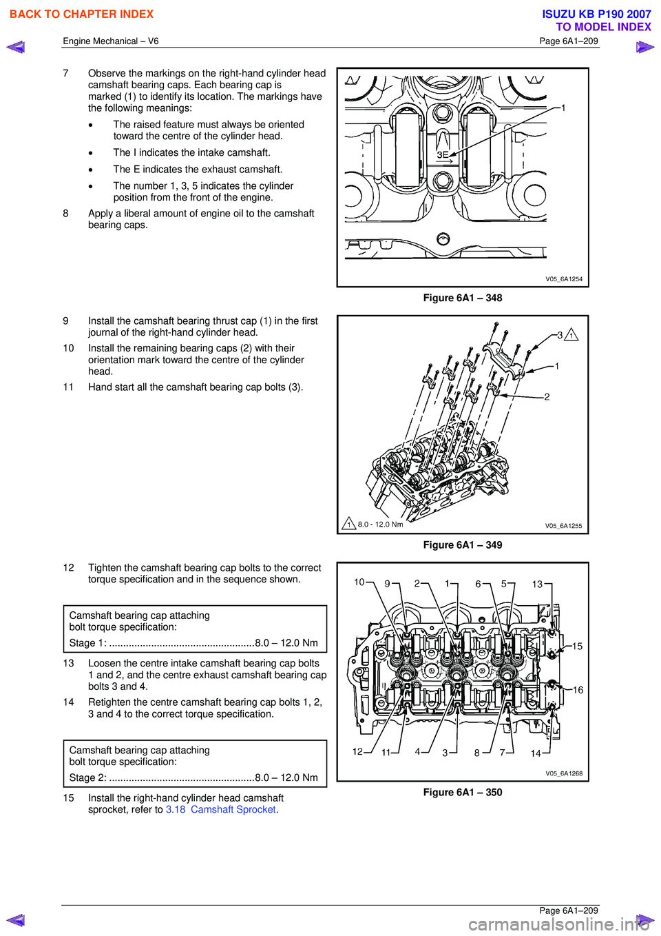
7 Observe the markings on the right-hand cylinder head
camshaft bearing caps. Each bearing cap is
marked (1) to identify its location. The markings have
the following meanings:
• The raised feature must always be oriented
toward the centre of the cylinder head.
• The I indicates the intake camshaft.
• The E indicates the exhaust camshaft.
• The number 1, 3, 5 indicates the cylinder
position from the fr ont of the engine.
8 Apply a liberal amount of engine oil to the camshaft bearing caps.
Figure 6A1 – 348
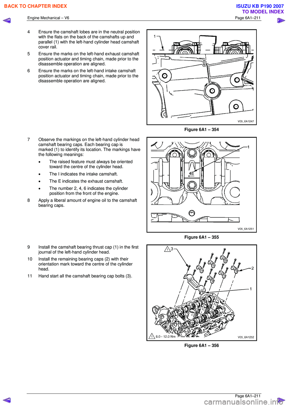
9 Install the camshaft bearing thrust cap (1) in the first journal of the right-hand cylinder head.
10 Install the remaining bearing caps (2) with their orientation mark toward t he centre of the cylinder
head.
11 Hand start all the camshaft bearing cap bolts (3).
Figure 6A1 – 349
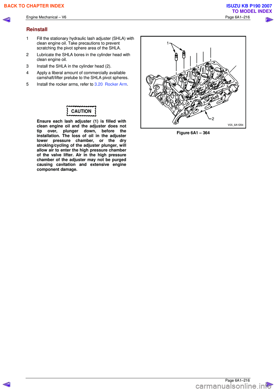
12 Tighten the camshaft bearing cap bolts to the correct torque specification and in the sequence shown.
Camshaft bearing cap attaching
bolt torque specification:
Stage 1: .................................................... 8.0 – 12.0 Nm
13 Loosen the centre intake camshaft bearing cap bolts
1 and 2, and the centre exhaust camshaft bearing cap
bolts 3 and 4.
14 Retighten the centre camsha ft bearing cap bolts 1, 2,
3 and 4 to the correct torque specification.
Camshaft bearing cap attaching
bolt torque specification:
Stage 2: .................................................... 8.0 – 12.0 Nm
15 Install the right-hand cylinder head camshaft
sprocket, refer to 3.18 Camshaft Sprocket .
Figure 6A1 – 350
BACK TO CHAPTER INDEX
TO MODEL INDEX
ISUZU KB P190 2007
Page 2987 of 6020
Engine Mechanical – V6 Page 6A1–210
Page 6A1–210
Left-hand Side
1 Select the correct camshaft for the particular
installation location. ID markings can be found on the
rear end of each camshaft. The ID markings are
defined as follows:
• The first five digits refer to the date and time of
production.
• Example = 3L18H.
• Digits six through nine refer to engine
production code.
• LY7 = Alloytec 190 engine.
• The last two digits refer to position:
• LI = left-hand intake.
• LE = left-hand exhaust.
• RI = right-hand intake.
• RE = right-hand exhaust.
Figure 6A1 – 351
2 Apply a liberal amount of engine oil to the camshaft journals and the left-hand cylinder head camshaft
carriers.
Figure 6A1 – 352
3 Position the camshafts (1) on the cylinder head and assemble the camshaft spro ckets to the camshafts.
NOTE
Install the camshaft sprocket bolts but do not
tighten at this stage.
Figure 6A1 – 353
BACK TO CHAPTER INDEX
TO MODEL INDEX
ISUZU KB P190 2007
Page 2988 of 6020

Engine Mechanical – V6 Page 6A1–211
Page 6A1–211
4 Ensure the camshaft lobes are in the neutral position
with the flats on the back of the camshafts up and
parallel (1) with the left-hand cylinder head camshaft
cover rail.
5 Ensure the marks on the left-hand exhaust camshaft position actuator and timing chain, made prior to the
disassemble operation are aligned.
6 Ensure the marks on the left-hand intake camshaft position actuator and timing chain, made prior to the
disassemble operation are aligned.
Figure 6A1 – 354
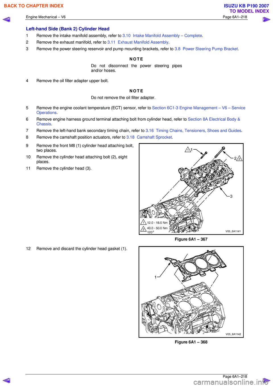
7 Observe the markings on the left-hand cylinder head camshaft bearing caps. Each bearing cap is
marked (1) to identify its location. The markings have
the following meanings:
• The raised feature must always be oriented
toward the centre of the cylinder head.
• The I indicates the intake camshaft.
• The E indicates the exhaust camshaft.
• The number 2, 4, 6 indicates the cylinder
position from the fr ont of the engine.
8 Apply a liberal amount of engine oil to the camshaft bearing caps.
Figure 6A1 – 355
9 Install the camshaft bearing thrust cap (1) in the first journal of the left-hand cylinder head.
10 Install the remaining bearing caps (2) with their orientation mark toward t he centre of the cylinder
head.
11 Hand start all the camshaft bearing cap bolts (3).
Figure 6A1 – 356
BACK TO CHAPTER INDEX
TO MODEL INDEX
ISUZU KB P190 2007
Page 2991 of 6020
Engine Mechanical – V6 Page 6A1–214
Page 6A1–214
Reinstall
1 Apply a liberal amount of commercially available
camshaft / lifter prelube or equivalent to the pivot
pocket (1), roller (2) and valve slot (3) areas of the
camshaft followers.
Figure 6A1 – 360
2 Place the rocker arm in position on the valve tip and stationary hydraulic lash adjuster (SHLA). The
rounded head end of the arm seats on the SHLA
while the flat end seats on the valve tip.
CAUTION
• The rocker arm (1) must be positioned
squarely on the valve tip so the full width
of the roller will completely contact the
camshaft lobe.
• If the rocker arms are being reused, they
must be reinstalled in their original
location.
3 Clean the camshaft journals and carriers with a clean, lint-free cloth.
4 Reinstall the camshafts, refer to 3.19 Camshaft.
Figure 6A1 – 361
BACK TO CHAPTER INDEX
TO MODEL INDEX
ISUZU KB P190 2007
Page 2993 of 6020

Engine Mechanical – V6 Page 6A1–216
Page 6A1–216
Reinstall
1 Fill the stationary hydraulic lash adjuster (SHLA) with
clean engine oil. Take precautions to prevent
scratching the pivot s phere area of the SHLA.
2 Lubricate the SHLA bores in the cylinder head with clean engine oil.
3 Install the SHLA in the cylinder head (2).
4 Apply a liberal amount of commercially available camshaft/lifter prelube to the SHLA pivot spheres.
5 Install the rocker arms, refer to 3.20 Rocker Arm.
CAUTION
Ensure each lash adjuster (1) is filled with
clean engine oil and the adjuster does not
tip over, plunger down, before the
installation. The loss of oil in the adjuster
lower pressure chamber, or the dry
stroking/cycling of the adjuster plunger, will
allow air to enter the high pressure chamber
of the valve lifter. Air in the high pressure
chamber of the adjuster may not be purged
causing cavitation and extensive engine
component damage.
Figure 6A1 – 364
BACK TO CHAPTER INDEX
TO MODEL INDEX
ISUZU KB P190 2007
Page 2995 of 6020

Engine Mechanical – V6 Page 6A1–218
Page 6A1–218
Left-hand Side (Bank 2) Cylinder Head
1 Remove the intake manifold assembly, refer to 3.10 Intake Manifold Assembly – Complete .
2 Remove the exhaust manifold, refer to 3.11 Exhaust Manifold Assembly.
3 Remove the power steering reservoi r and pump mounting brackets, refer to 3.8 Power Steering Pump Bracket.
NOTE
Do not disconnect the power steering pipes
and/or hoses.
4 Remove the oil filter adapter upper bolt. NOTE
Do not remove the oil filter adapter.
5 Remove the engine coolant temper ature (ECT) sensor, refer to Section 6C1-3 Engine Management – V6 – Service
Operations .
6 Remove engine harness ground terminal attach ing bolt from cylinder head, refer to Section 8A Electrical Body &
Chassis .
7 Remove the left-hand bank secondary timing chain, refer to 3.16 Timing Chains, Tensioners, Shoes and Guides.
8 Remove the camshaft position actuators, refer to 3.18 Camshaft Sprocket.
9 Remove the front M8 (1) cylinder head attaching bolt, two places.
10 Remove the cylinder head attaching bolt (2), eight places.
11 Remove the cylinder head (3).
Figure 6A1 – 367
12 Remove and discard the cylinder head gasket (1).
Figure 6A1 – 368
BACK TO CHAPTER INDEX
TO MODEL INDEX
ISUZU KB P190 2007