Page 2913 of 6020
Engine Mechanical – V6 Page 6A1–136
Page 6A1–136
21 Install the left-hand secondary timing chain shoe
bolt (1) and tighten to the co rrect torque specification.
NOTE
Ensure secondary timing chain shoe is clear of
the left-hand secondary timing chain tensioner
mounting pad, before ti ghtening the attaching
bolt.
Secondary timing chain shoe attaching
bolt torque specificat ion .......................... 20.0 – 26.0 Nm
Figure 6A1 – 161
22 Ensure the left-hand secondary timing chain tensioner is selected and orientated correctly.
Figure 6A1 – 162
23 Reset the left-hand secondary timing chain tensioner.
NOTE
To reset the tensioner, use a suitably sized flat
blade screwdriver (1) or Tool No. J 45027 (4) to
wind the plunger in a clockwise direction, into
the tensioner shaft (2).
Figure 6A1 – 163
BACK TO CHAPTER INDEX
TO MODEL INDEX
ISUZU KB P190 2007
Page 2914 of 6020
Engine Mechanical – V6 Page 6A1–137
Page 6A1–137
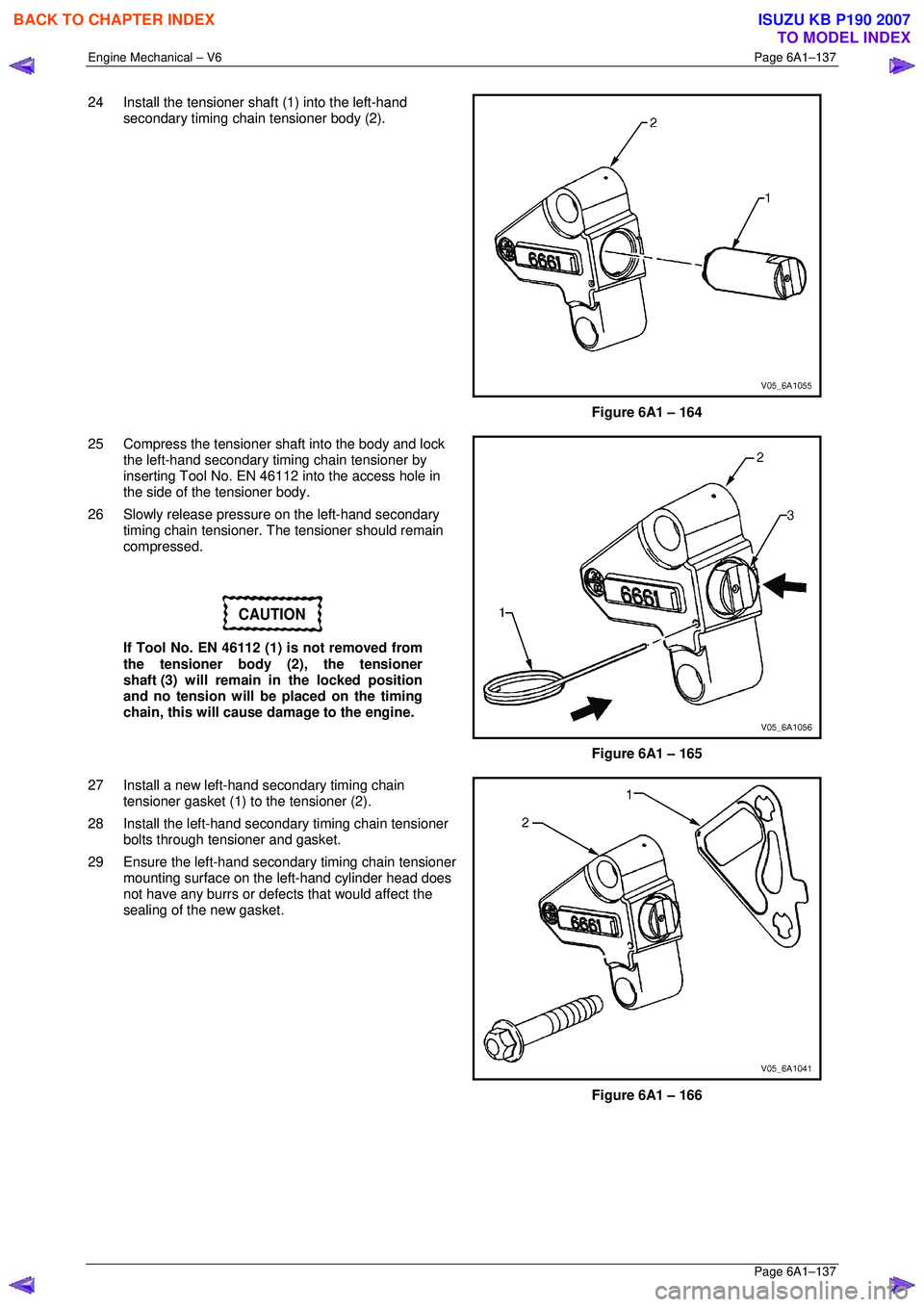
24 Install the tensioner shaft (1) into the left-hand
secondary timing chain tensioner body (2).
Figure 6A1 – 164
25 Compress the tensioner shaft into the body and lock the left-hand secondary timing chain tensioner by
inserting Tool No. EN 46112 into the access hole in
the side of the tensioner body.
26 Slowly release pressure on the left-hand secondary timing chain tensioner. The tensioner should remain
compressed.
CAUTION
If Tool No. EN 46112 (1) is not removed from
the tensioner body (2), the tensioner
shaft (3) will remain in the locked position
and no tension will be placed on the timing
chain, this will cause damage to the engine.
Figure 6A1 – 165
27 Install a new left-hand secondary timing chain tensioner gasket (1) to the tensioner (2).
28 Install the left-hand secondar y timing chain tensioner
bolts through tensioner and gasket.
29 Ensure the left-hand secondary timing chain tensioner mounting surface on the left-hand cylinder head does
not have any burrs or defects that would affect the
sealing of the new gasket.
Figure 6A1 – 166
BACK TO CHAPTER INDEX
TO MODEL INDEX
ISUZU KB P190 2007
Page 2922 of 6020
Engine Mechanical – V6 Page 6A1–145
Page 6A1–145
CAUTION
The left-hand secondary timing chain shoe
(2) is marked with the letters LH on the back
face of the timing chain shoe. Ensure the
correct shoe is used when installing to the
left-hand side.
19 Ensure the left-hand secondary timing chain shoe is selected and orientated correctly.
Figure 6A1 – 186
20 Install the left-hand secondary timing chain shoe (1).
Figure 6A1 – 187
21 Install the left-hand secondary timing chain shoe bolt (1) and tighten to the co rrect torque specification.
NOTE
Ensure secondary timing chain shoe is clear of
the left-hand secondary timing chain tensioner
mounting pad, before ti ghtening the attaching
bolt.
Secondary timing chain shoe attaching
bolt torque specificat ion .......................... 20.0 – 26.0 Nm
Figure 6A1 – 188
BACK TO CHAPTER INDEX
TO MODEL INDEX
ISUZU KB P190 2007
Page 2924 of 6020
Engine Mechanical – V6 Page 6A1–147
Page 6A1–147
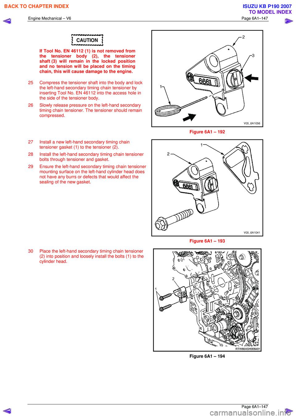
CAUTION
If Tool No. EN 46112 (1) is not removed from
the tensioner body (2), the tensioner
shaft (3) will remain in the locked position
and no tension will be placed on the timing
chain, this will cause damage to the engine.
25 Compress the tensioner shaft into the body and lock the left-hand secondary timing chain tensioner by
inserting Tool No. EN 46112 into the access hole in
the side of the tensioner body.
26 Slowly release pressure on the left-hand secondary timing chain tensioner. The tensioner should remain
compressed.
Figure 6A1 – 192
27 Install a new left-hand secondary timing chain tensioner gasket (1) to the tensioner (2).
28 Install the left-hand secondar y timing chain tensioner
bolts through tensioner and gasket.
29 Ensure the left-hand secondary timing chain tensioner mounting surface on the left-hand cylinder head does
not have any burrs or defects that would affect the
sealing of the new gasket.
Figure 6A1 – 193
30 Place the left-hand secondar y timing chain tensioner
(2) into position and loosely install the bolts (1) to the
cylinder head.
Figure 6A1 – 194
BACK TO CHAPTER INDEX
TO MODEL INDEX
ISUZU KB P190 2007
Page 2931 of 6020
Engine Mechanical – V6 Page 6A1–154
Page 6A1–154
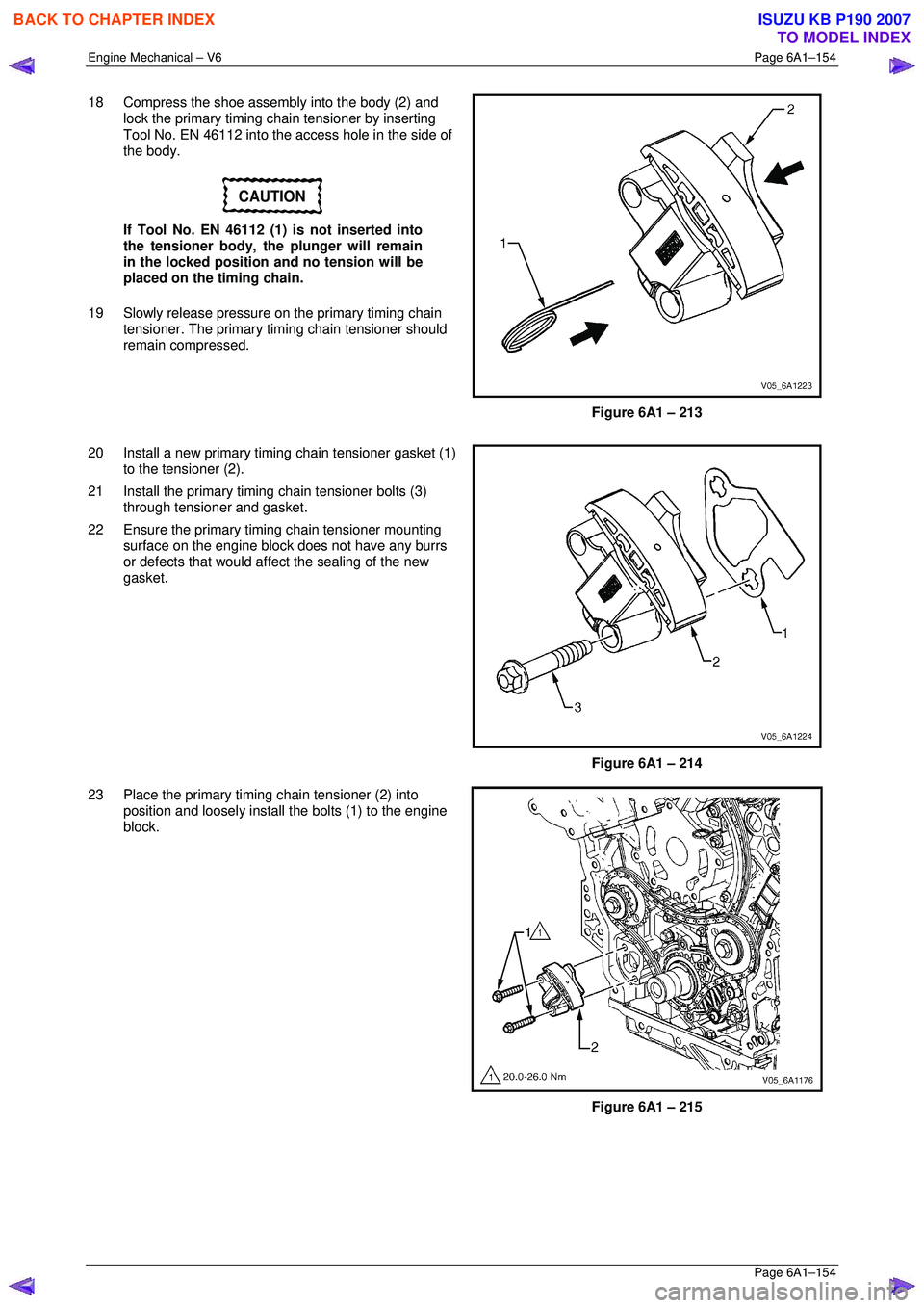
18 Compress the shoe assembly into the body (2) and
lock the primary timing chai n tensioner by inserting
Tool No. EN 46112 into the access hole in the side of
the body.
CAUTION
If Tool No. EN 46112 (1) is not inserted into
the tensioner body, the plunger will remain
in the locked position and no tension will be
placed on the timing chain.
19 Slowly release pressure on the primary timing chain tensioner. The primary timi ng chain tensioner should
remain compressed.
Figure 6A1 – 213
20 Install a new primary timing chain tensioner gasket (1) to the tensioner (2).
21 Install the primary timing chain tensioner bolts (3)
through tensioner and gasket.
22 Ensure the primary timi ng chain tensioner mounting
surface on the engine block does not have any burrs
or defects that would affe ct the sealing of the new
gasket.
Figure 6A1 – 214
23 Place the primary timing chain tensioner (2) into position and loosely install the bolts (1) to the engine
block.
Figure 6A1 – 215
BACK TO CHAPTER INDEX
TO MODEL INDEX
ISUZU KB P190 2007
Page 2939 of 6020
Engine Mechanical – V6 Page 6A1–162
Page 6A1–162
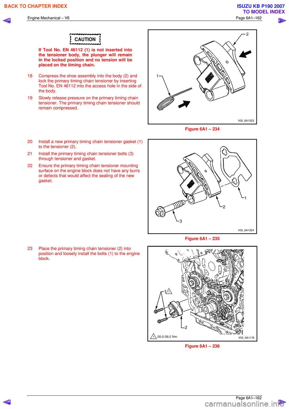
CAUTION
If Tool No. EN 46112 (1) is not inserted into
the tensioner body, the plunger will remain
in the locked position and no tension will be
placed on the timing chain.
18 Compress the shoe assembly into the body (2) and lock the primary timing chai n tensioner by inserting
Tool No. EN 46112 into the access hole in the side of
the body.
19 Slowly release pressure on the primary timing chain tensioner. The primary timi ng chain tensioner should
remain compressed.
Figure 6A1 – 234
20 Install a new primary timing chain tensioner gasket (1) to the tensioner (2).
21 Install the primary timing chain tensioner bolts (3)
through tensioner and gasket.
22 Ensure the primary timi ng chain tensioner mounting
surface on the engine block does not have any burrs
or defects that would affe ct the sealing of the new
gasket.
Figure 6A1 – 235
23 Place the primary timing chain tensioner (2) into position and loosely install the bolts (1) to the engine
block.
Figure 6A1 – 236
BACK TO CHAPTER INDEX
TO MODEL INDEX
ISUZU KB P190 2007
Page 2947 of 6020
Engine Mechanical – V6 Page 6A1–170
Page 6A1–170
19 Compress the tensioner shaft into the body and lock
the tensioner by inserting Tool No. EN 46112 into the
access hole in the side of the tensioner body.
20 Slowly release pressure on the right-hand secondary timing chain tensioner. The tensioner should remain
compressed.
Figure 6A1 – 257
21 Install a new right-hand secondary timing chain tensioner gasket (1) to the tensioner (2).
22 Install the right-hand secondary timing chain tensioner bolts (3) through the tensioner and gasket.
23 Ensure the right-hand secondary timing chain tensioner mounting surfac e on the right-hand cylinder
head does not have any burrs or defects that would
affect the sealing of the new tensioner gasket.
Figure 6A1 – 258
24 Place the right-hand secondar y timing chain tensioner
(2) into position and loosely install the bolts (1) to the
engine block.
Figure 6A1 – 259
BACK TO CHAPTER INDEX
TO MODEL INDEX
ISUZU KB P190 2007
Page 2955 of 6020
Engine Mechanical – V6 Page 6A1–178
Page 6A1–178
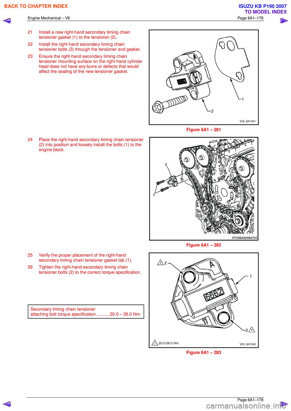
21 Install a new right-hand secondary timing chain
tensioner gasket (1) to the tensioner (2).
22 Install the right-hand secondary timing chain tensioner bolts (3) through the tensioner and gasket.
23 Ensure the right-hand secondary timing chain tensioner mounting surfac e on the right-hand cylinder
head does not have any burrs or defects that would
affect the sealing of the new tensioner gasket.
Figure 6A1 – 281
24 Place the right-hand secondar y timing chain tensioner
(2) into position and loosely install the bolts (1) to the
engine block.
Figure 6A1 – 282
25 Verify the proper plac ement of the right-hand
secondary timing chain tensioner gasket tab (1).
26 Tighten the right-hand secondary timing chain tensioner bolts (2) to the co rrect torque specification.
Secondary timing chain tensioner
attaching bolt torque spec ification ........... 20.0 – 26.0 Nm
Figure 6A1 – 283
BACK TO CHAPTER INDEX
TO MODEL INDEX
ISUZU KB P190 2007