2007 ISUZU KB P190 Circuit
[x] Cancel search: CircuitPage 1318 of 6020
6E-284 Engine Control System (4JH1)
Important:
To prevent possible electrostatic discharge damage,
follow these guidelines: • Do not touch the ECM connector pins or soldered
components on the ECM circuit board.
• Do not open the replacement part package until
the part is ready to be installed.
• Before removing the part from the package,
ground the package to a known good ground on
the vehicle.
• If the part has been handled while sliding across
the seat, while sitting down from a standing
position, or while walking a distance, touch a
known good ground before installing the part.
• Charge by induction occurs when a person with
well insulated shoes stands near a highly charged
object and momentarily touches ground. Charges
of the same polarity are drained off leaving the
person highly charged with opposite polarity.
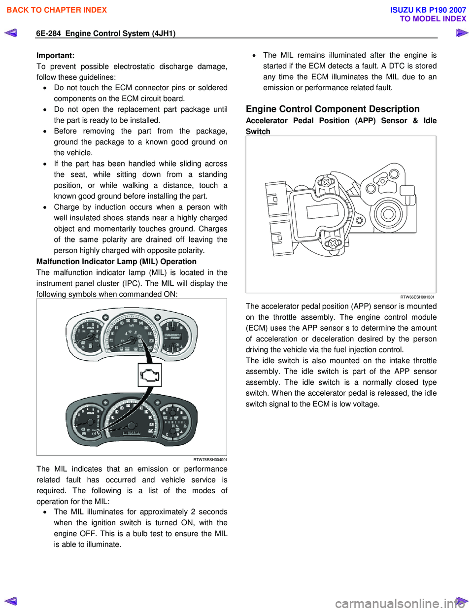
Malfunction Indicator Lamp (MIL) Operation
The malfunction indicator lamp (MIL) is located in the
instrument panel cluster (IPC). The MIL will display the
following symbols when commanded ON:
RTW 76ESH004001
The MIL indicates that an emission or performance
related fault has occurred and vehicle service is
required. The following is a list of the modes o
f
operation for the MIL: • The MIL illuminates for approximately 2 seconds
when the ignition switch is turned ON, with the
engine OFF. This is a bulb test to ensure the MIL
is able to illuminate.
•
The MIL remains illuminated after the engine is
started if the ECM detects a fault. A DTC is stored
any time the ECM illuminates the MIL due to an
emission or performance related fault.
Engine Control Component Description
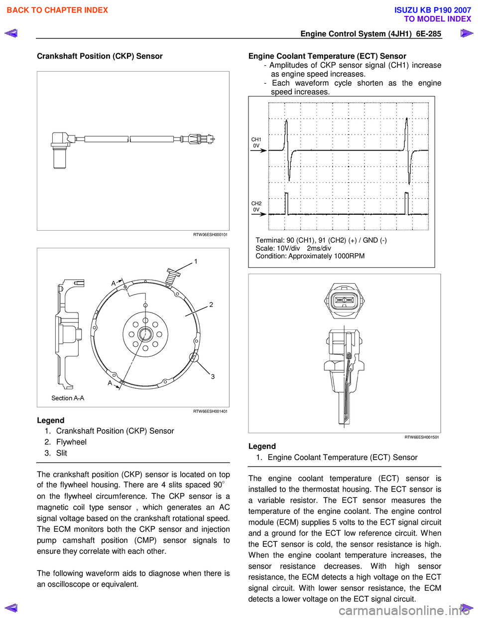
Accelerator Pedal Position (APP) Sensor & Idle
Switch
RTW 66ESH001301
The accelerator pedal position (APP) sensor is mounted
on the throttle assembly. The engine control module
(ECM) uses the APP sensor s to determine the amount
of acceleration or deceleration desired by the person
driving the vehicle via the fuel injection control.
The idle switch is also mounted on the intake throttle
assembly. The idle switch is part of the APP senso
r
assembly. The idle switch is a normally closed type
switch. W hen the accelerator pedal is released, the idle
switch signal to the ECM is low voltage.
BACK TO CHAPTER INDEX
TO MODEL INDEX
ISUZU KB P190 2007
Page 1319 of 6020
Engine Control System (4JH1) 6E-285
Crankshaft Position (CKP) Sensor
RTW 06ESH000101
RTW 66ESH001401
Legend
1. Crankshaft Position (CKP) Sensor
2. Flywheel
3. Slit
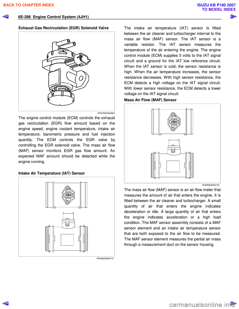
The crankshaft position (CKP) sensor is located on top
of the flywheel housing. There are 4 slits spaced 90 °
on the flywheel circumference. The CKP sensor is a
magnetic coil type sensor , which generates an AC
signal voltage based on the crankshaft rotational speed.
The ECM monitors both the CKP sensor and injection
pump camshaft position (CMP) sensor signals to
ensure they correlate with each other.
The following waveform aids to diagnose when there is
an oscilloscope or equivalent.
Engine Coolant Temperature (ECT) Sensor
- Amplitudes of CKP sensor signal (CH1) increase as engine speed increases.
- Each waveform cycle shorten as the engine speed increases.
Terminal: 90 (CH1), 91 (CH2) (+) / GND (-)
Scale: 10V/div 2ms/div
Condition: Approximately 1000RPM
CH1
0V
CH2 0V
RTW 66ESH001501
Legend
1. Engine Coolant Temperature (ECT) Sensor
The engine coolant temperature (ECT) sensor is
installed to the thermostat housing. The ECT sensor is
a variable resistor. The ECT sensor measures the
temperature of the engine coolant. The engine control
module (ECM) supplies 5 volts to the ECT signal circuit
and a ground for the ECT low reference circuit. W hen
the ECT sensor is cold, the sensor resistance is high.
W hen the engine coolant temperature increases, the
sensor resistance decreases. W ith high senso
r
resistance, the ECM detects a high voltage on the ECT
signal circuit. W ith lower sensor resistance, the ECM
detects a lower voltage on the ECT signal circuit.
BACK TO CHAPTER INDEX
TO MODEL INDEX
ISUZU KB P190 2007
Page 1320 of 6020
6E-286 Engine Control System (4JH1)
Exhaust Gas Recirculation (EGR) Solenoid Valve
RTW 76ESH003601
The engine control module (ECM) controls the exhaust
gas recirculation (EGR) flow amount based on the
engine speed, engine coolant temperature, intake ai
r
temperature, barometric pressure and fuel injection
quantity. The ECM controls the EGR valve b
y
controlling the EGR solenoid valve. The mass air flo
w
(MAF) sensor monitors EGR gas flow amount. An
expected MAF amount should be detected while the
engine running.
Intake Air Temperature (IAT) Sensor
RTW 66ESH001701
The intake air temperature (IAT) sensor is fitted
between the air cleaner and turbocharger internal to the
mass air flow (MAF) sensor. The IAT sensor is a
variable resistor. The IAT sensor measures the
temperature of the air entering the engine. The engine
control module (ECM) supplies 5 volts to the IAT signal
circuit and a ground for the IAT low reference circuit.
W hen the IAT sensor is cold, the sensor resistance is
high. W hen the air temperature increases, the senso
r
resistance decreases. W ith high sensor resistance, the
ECM detects a high voltage on the IAT signal circuit.
W ith lower sensor resistance, the ECM detects a lowe
r
voltage on the IAT signal circuit.
Mass Air Flow (MAF) Sensor
RTW 66ESH001701
The mass air flow (MAF) sensor is an air flow meter that
measures the amount of air that enters the engine. It is
fitted between the air cleaner and turbocharger. A small
quantity of air that enters the engine indicates
deceleration or idle. A large quantity of air that enters
the engine indicates acceleration or a high load
condition. The MAF sensor assembly consists of a MAF
sensor element and an intake air temperature senso
r
that are both exposed to the air flow to be measured.
The MAF sensor element measures the partial air mass
through a measurement duct on the sensor housing.
BACK TO CHAPTER INDEX
TO MODEL INDEX
ISUZU KB P190 2007
Page 1324 of 6020
6E-290 Engine Control System (4JH1)
Low Pressure Fuel Circuit Description
RTW 66ESH002101
Legend
1. Fuel Suction
2. Regulating Valve
3. Overflow Valve
4. Feed Pump
5. To Fuel Tank
The low pressure fuel circuit must supply sufficient fuel
to the high pressure fuel circuit. The main components
are the feed pump, the regulating valve and the
overflow valve.
Feed Pump
RTW 66ESH002201
Legend
1. Rotor
2. Casing Ring
3. Fuel Supply
4. Outlet
5. Chamber
6. Vane
7. Driveshaft
8. Inlet
9. Fuel Suction
The feed pump is driven by the drive shaft, performs
suction and supply of fuel. The vanes assembled in the
rotor are pressed against the inside of the casing ring
by spring forces and centrifugal force during rotation to
form chambers. W hen the vanes rotate, the volume o
f
these chambers increase when they reach recesses the
casing ring connected to the inlet port. Pressure then
decreases and fuel is drawn in. W hen the chambers
have passed the inlets and recesses, the volume
decreases and the fuel is compressed. Fuel pressure
increases until the chamber reaches the outlet, where
the fuel passes through the regulating valve to the high
pressure fuel circuit.
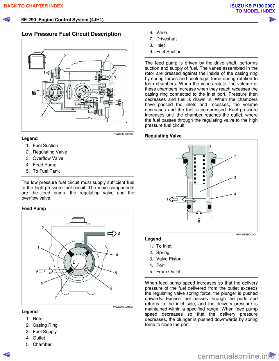
Regulating Valve
RTW 66ESH002301
Legend
1. To Inlet
2. Spring
3. Valve Piston
4. Port
5. From Outlet
W hen feed pump speed increases so that the delivery
pressure of the fuel delivered from the outlet exceeds
the regulating valve spring force, the plunger is pushed
upwards. Excess fuel passes through the ports and
returns to the inlet side, and the delivery pressure is
maintained within a specified range. W hen feed pump
speed decreases so that the delivery pressure
decreases, the plunger is pushed downwards by spring
force to close the port.
BACK TO CHAPTER INDEX
TO MODEL INDEX
ISUZU KB P190 2007
Page 1325 of 6020
Engine Control System (4JH1) 6E-291
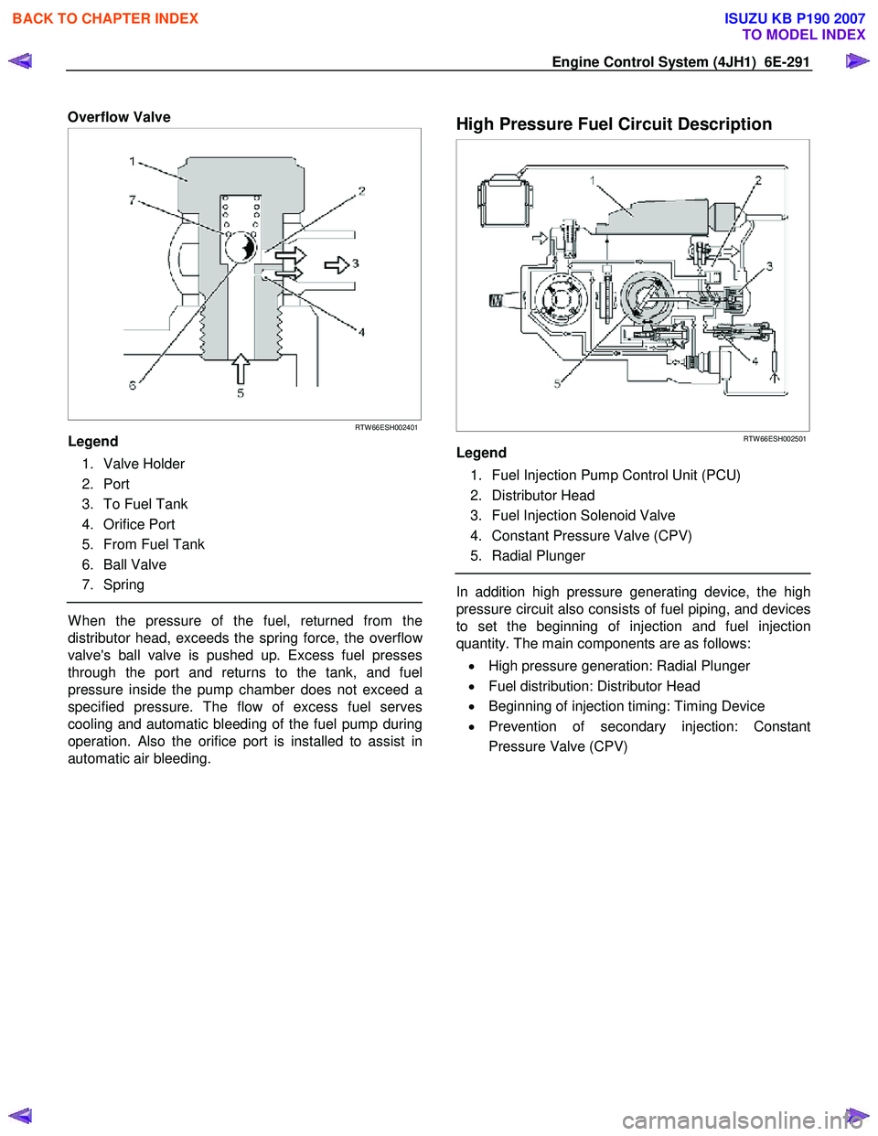
Overflow Valve
RTW 66ESH002401
Legend
1. Valve Holder
2. Port
3. To Fuel Tank
4. Orifice Port
5. From Fuel Tank
6. Ball Valve
7. Spring
W hen the pressure of the fuel, returned from the
distributor head, exceeds the spring force, the overflo
w
valve's ball valve is pushed up. Excess fuel presses
through the port and returns to the tank, and fuel
pressure inside the pump chamber does not exceed a
specified pressure. The flow of excess fuel serves
cooling and automatic bleeding of the fuel pump during
operation. Also the orifice port is installed to assist in
automatic air bleeding.
High Pressure Fuel Circuit Description
RTW 66ESH002501
Legend
1. Fuel Injection Pump Control Unit (PCU)
2. Distributor Head
3. Fuel Injection Solenoid Valve
4. Constant Pressure Valve (CPV)
5. Radial Plunger
In addition high pressure generating device, the high
pressure circuit also consists of fuel piping, and devices
to set the beginning of injection and fuel injection
quantity. The main components are as follows:
• High pressure generation: Radial Plunger
• Fuel distribution: Distributor Head
• Beginning of injection timing: Timing Device
• Prevention of secondary injection: Constant
Pressure Valve (CPV)
BACK TO CHAPTER INDEX
TO MODEL INDEX
ISUZU KB P190 2007
Page 1344 of 6020
EXHAUST SYSTEM 6F – 11
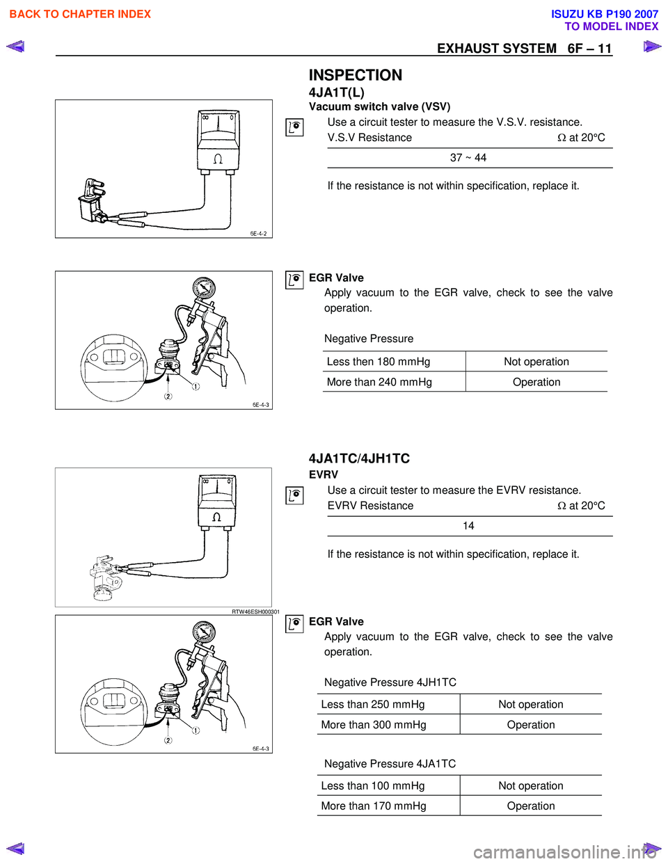
INSPECTION
4JA1T(L)
Vacuum switch valve (VSV)
Use a circuit tester to measure the V.S.V. resistance.
V.S.V Resistance Ω at 20°C
37 ~ 44
If the resistance is not within specification, replace it.
EGR Valve
Apply vacuum to the EGR valve, check to see the valve
operation.
Negative Pressure
4JA1TC/4JH1TC
RTW 46ESH000301
EVRV
Use a circuit tester to measure the EVRV resistance.
EVRV Resistance Ω at 20°C
14
If the resistance is not within specification, replace it.
EGR Valve
Apply vacuum to the EGR valve, check to see the valve
operation.
Negative Pressure 4JH1TC
Less than 250 mmHg Not operation
More than 300 mmHg Operation
Negative Pressure 4JA1TC
Less than 100 mmHg Not operation
More than 170 mmHg Operation
Less then 180 mmHg Not operation
More than 240 mmHg
Operation
BACK TO CHAPTER INDEX
TO MODEL INDEX
ISUZU KB P190 2007
Page 1362 of 6020
6A-2 ENGINE MECHANICAL (4JK1/4JJ1)
Special Tools ...................................................6A-110
Flywheel .............................................................6A-111 Components ....................................................6A-111
Removal ..........................................................6A-111
Inspection ........................................................6A-113
Installation .......................................................6A-113
Torque Specifications......................................6A-115
Special Tools ...................................................6A-115
Gear Case Assembly .........................................6A-116 Components ....................................................6A-116
Removal ..........................................................6A-117
Installation .......................................................6A-118
Torque Specifications......................................6A-119
Crankshaft Front Oil Seal ...................................6A-120 Components ....................................................6A-120
Removal ..........................................................6A-120
Installation .......................................................6A-121
Torque Specifications......................................6A-122
Special Tools ...................................................6A-122
Crankshaft Rear Oil Seal ...................................6A-123 Components ....................................................6A-123
Removal ..........................................................6A-124
Installation .......................................................6A-124
Special Tools ...................................................6A-125
Crankshaft ..........................................................6A-126 Components ....................................................6A-126
Removal ..........................................................6A-127
Disassembly ....................................................6A-127
Reassembly.....................................................6A-128
Inspection ........................................................6A-128
Installation .......................................................6A-132
Torque Specifications......................................6A-135
Cylinder Block ....................................................6A-136 Components ....................................................6A-136
Removal ..........................................................6A-136
Inspection ........................................................6A-137
Installation .......................................................6A-139
Lubrication System .............................................6A-140 Service Precautions ........................................6A-140
Functional Check ............................................6A-141
Oil Filter Cartridge ..............................................6A-143 Components ....................................................6A-143
Removal ..........................................................6A-143
Installation .......................................................6A-143
Special Tools ...................................................6A-144
Oil Filter Assembly and Oil Cooler .....................6A-145 Components ....................................................6A-145
Removal ..........................................................6A-145
Disassembly ....................................................6A-146
Reassembly.....................................................6A-147 Installation ....................................................... 6A-147
Crank Case and Oil Pan .................................... 6A-150 Components .................................................... 6A-150
Removal .......................................................... 6A-151
Disassembly .................................................... 6A-152
Reassembly .................................................... 6A-152
Installation ....................................................... 6A-153
Torque Specifications...................................... 6A-155
Oil Pump ............................................................ 6A-156 Components .................................................... 6A-156
Removal .......................................................... 6A-156
Disassembly .................................................... 6A-157
Reassembly .................................................... 6A-158
Inspection ........................................................ 6A-158
Installation ....................................................... 6A-159
Oil Pressure SW ................................................ 6A-161 Components .................................................... 6A-161
Removal .......................................................... 6A-162
Inspection ........................................................ 6A-162
Installation ....................................................... 6A-162
Circuit check.................................................... 6A-162
Air Cleaner Element ........................................... 6A-163 Removal .......................................................... 6A-163
Cleaning .......................................................... 6A-163
Installation ....................................................... 6A-163
BACK TO CHAPTER INDEX
TO MODEL INDEX
ISUZU KB P190 2007
Page 1363 of 6020
ENGINE MECHANICAL (4JK1/4JJ1) 6A-3
ISUZU DIESEL ENGINE (4JK1/4JJ1)
Service Precautions
Matters that require attention in terms of
maintenance
To prevent damage to the engine and ensure reliabilit
y
of its performance, pay attention to the following in
maintaining the engine:
• W hen lifting up or supporting the engine, do not
apply a jack on the oil pan.
W hen taking down the engine on the ground, do not make the bearing surface of the oil pan touch
the ground directly. Use a wooden frame, fo
r
example, to support the engine with the engine
foot and the flywheel housing.
Because there is only a small clearance between the oil pan and the oil pump strainer, it can
damage the oil pan and the oil strainer.
• W hen the air duct or air cleaner is removed, cove
r
the air intake opening to prevent foreign matter
from getting into the cylinder. If it gets
contaminated, it can considerably damage the
cylinder and others while the engine is operating.
• W hen maintaining the engine, never fail to remove
the battery earth cable. If not, it may damage the
wire harness or electrical parts. If you need
electricity on for the purpose of inspection, fo
r
instance, watch out for short circuits and others.
•
Apply engine oil to the sliding contact surfaces of
the engine before reassembling it. This ensures
adequate lubrication when the engine is first
started.
• W hen valve train parts, pistons, piston rings,
connecting rods, connecting rod bearings o
r
crankshaft journal bearings are removed, put them
in order and keep them.
• W hen installing them, put them back in the same
location they were removed from.
• Gaskets, oil seals, O-rings, etc. must be replaced
with new ones when the engine is reassembled.
•
As for parts where a liquid gasket is used, remove
an old liquid gasket completely and clean it up
thoroughly so that no oil, water or dust is clinging
to them. Then, apply the designated liquid gasket
to each place anew before assembly.
• Surfaces covered with liquid gasket must be
assembled within 5 minutes of gasket application.
If more than 5 minutes has elapsed, remove the
existing liquid gasket and apply a new liquid
gasket.
• W hen assembling or installing parts, fasten them
with the prescribed tightening torque so that the
y
are installed properly.
Matters that require attention in specifically dealing
with this engine.
Holes or clearances in the fuel system, which serve as
a passage of fuel, including the inside of the injector,
are made with extreme precision. For this reason, the
y
are highly sensitive to foreign matter and, if it gets in, it
can lead to an accident on the road, for instance; thus,
make sure that foreign matter is prevented from getting
in.
W hen servicing the fuel system, every precaution must
be taken to prevent the entry of foreign material into the
system.
• Before beginning the service procedure, wash the
fuel line and the surrounding area.
• Perform the service procedures with clean hands.
Do not wear work gloves.
• Immediately after removing the fuel hose and/o
r
fuel pipe, carefully tape vinyl bags over the
exposed ends of the hose or pipe.
• If parts are to be replaced (fuel hose, fuel pipe,
etc.) do not open the new part packaging until
installation.
Work procedure
• The fuel opening must be quickly sealed when
removing the fuel pipe, injection pipe, fuel injector,
fuel supply pump, and fuel rail.
• The eyebolts and gasket must be stored in a clean
parts box with a lid to prevent adhesion of foreign
matter.
• Fuel leakage could cause fires. Therefore, afte
r
finishing the work, wipe off the fuel that has leaked
out and make sure there is no fuel leakage afte
r
starting the engine.
BACK TO CHAPTER INDEX
TO MODEL INDEX
ISUZU KB P190 2007