2007 ISUZU KB P190 Circuit
[x] Cancel search: CircuitPage 1368 of 6020
6A-8 ENGINE MECHANICAL (4JK1/4JJ1)
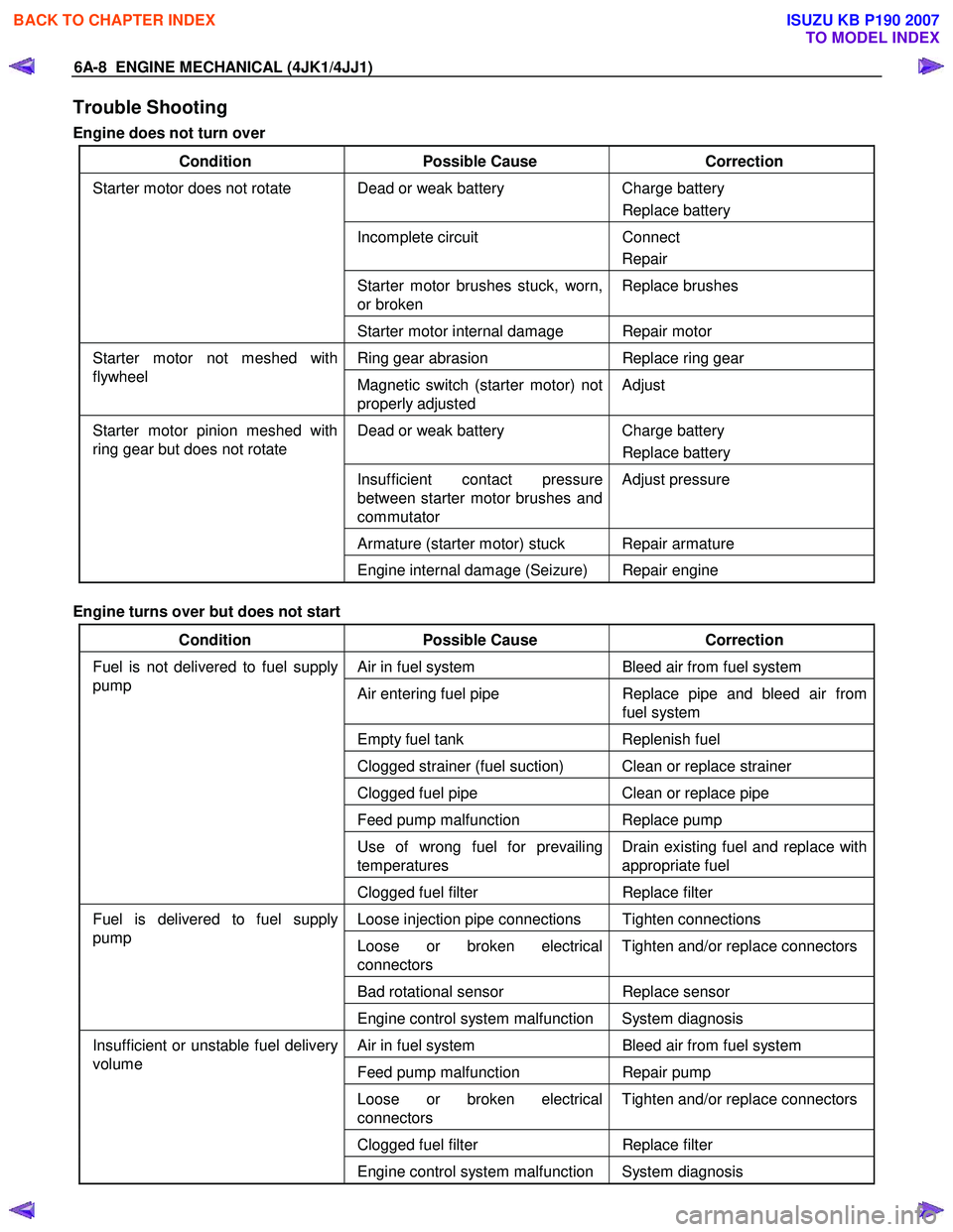
Trouble Shooting
Engine does not turn over
Condition Possible Cause Correction
Dead or weak battery Charge battery
Replace battery
Incomplete circuit Connect
Repair
Starter motor brushes stuck, worn,
or broken Replace brushes
Starter motor does not rotate
Starter motor internal damage Repair motor
Ring gear abrasion Replace ring gear Starter motor not meshed with
flywheel Magnetic switch (starter motor) not
properly adjusted Adjust
Dead or weak battery
Charge battery
Replace battery
Insufficient contact pressure
between starter motor brushes and
commutator Adjust pressure
Armature (starter motor) stuck Repair armature
Starter motor pinion meshed with
ring gear but does not rotate
Engine internal damage (Seizure) Repair engine
Engine turns over but does not start
Condition Possible Cause Correction
Air in fuel system Bleed air from fuel system
Air entering fuel pipe Replace pipe and bleed air from
fuel system
Empty fuel tank Replenish fuel
Clogged strainer (fuel suction) Clean or replace strainer
Clogged fuel pipe Clean or replace pipe
Feed pump malfunction Replace pump
Use of wrong fuel for prevailing
temperatures Drain existing fuel and replace with
appropriate fuel
Fuel is not delivered to fuel supply
pump
Clogged fuel filter Replace filter
Loose injection pipe connections Tighten connections
Loose or broken electrical
connectors Tighten and/or replace connectors
Bad rotational sensor
Replace sensor
Fuel is delivered to fuel supply
pump
Engine control system malfunction System diagnosis
Air in fuel system Bleed air from fuel system
Feed pump malfunction Repair pump
Loose or broken electrical
connectors Tighten and/or replace connectors
Clogged fuel filter
Replace filter
Insufficient or unstable fuel delivery
volume
Engine control system malfunction System diagnosis
BACK TO CHAPTER INDEX
TO MODEL INDEX
ISUZU KB P190 2007
Page 1522 of 6020
6A-162 ENGINE MECHANICAL (4JK1/4JJ1)
Removal
1. Remove the oil pressure SW .
2. Remove the nipple; oil gallery.
3. Remove the nipple; oil pressure warning SW and gasket.
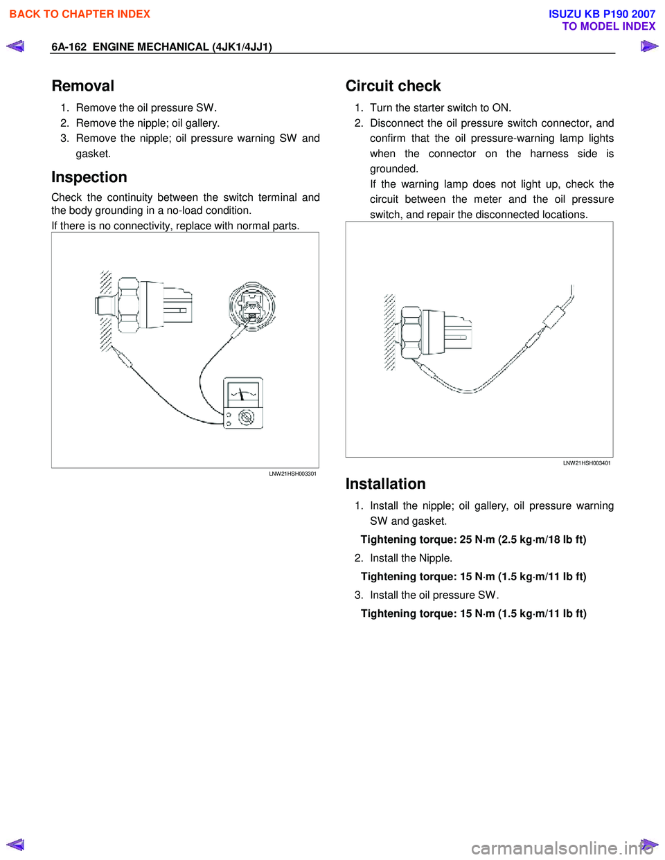
Inspection
Check the continuity between the switch terminal and
the body grounding in a no-load condition.
If there is no connectivity, replace with normal parts.
LNW 21HSH003301
Circuit check
1. Turn the starter switch to ON.
2. Disconnect the oil pressure switch connector, and confirm that the oil pressure-warning lamp lights
when the connector on the harness side is
grounded.
If the warning lamp does not light up, check the circuit between the meter and the oil pressure
switch, and repair the disconnected locations.
LNW 21HSH003401
Installation
1. Install the nipple; oil gallery, oil pressure warning
SW and gasket.
Tightening torque: 25 N ⋅
⋅⋅
⋅
m (2.5 kg ⋅
⋅⋅
⋅
m/18 lb ft)
2. Install the Nipple. Tightening torque: 15 N ⋅
⋅⋅
⋅
m (1.5 kg ⋅
⋅⋅
⋅
m/11 lb ft)
3. Install the oil pressure SW . Tightening torque: 15 N ⋅
⋅⋅
⋅
m (1.5 kg ⋅
⋅⋅
⋅
m/11 lb ft)
BACK TO CHAPTER INDEX
TO MODEL INDEX
ISUZU KB P190 2007
Page 1529 of 6020
6B-6 ENGINE COOLING (4JK1/4JJ1)
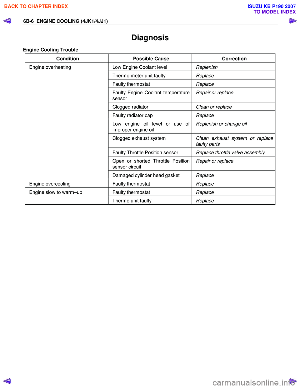
Diagnosis
Engine Cooling Trouble
Condition Possible Cause Correction
Low Engine Coolant level Replenish
Thermo meter unit faulty Replace
Faulty thermostat Replace
Faulty Engine Coolant temperature
sensor Repair or replace
Clogged radiator
Clean or replace
Faulty radiator cap Replace
Low engine oil level or use of
improper engine oil Replenish or change oil
Clogged exhaust system
Clean exhaust system or replace
faulty parts
Faulty Throttle Position sensor Replace throttle valve assembly
Open or shorted Throttle Position
sensor circuit Repair or replace
Engine overheating
Damaged cylinder head gasket Replace
Engine overcooling Faulty thermostat Replace
Faulty thermostat Replace Engine slow to warm–up
Thermo unit faulty Replace
BACK TO CHAPTER INDEX
TO MODEL INDEX
ISUZU KB P190 2007
Page 1580 of 6020
FUEL SYSTEM (4JK1/4JJ1) 6C-39
Fuel Sedimenter Switch
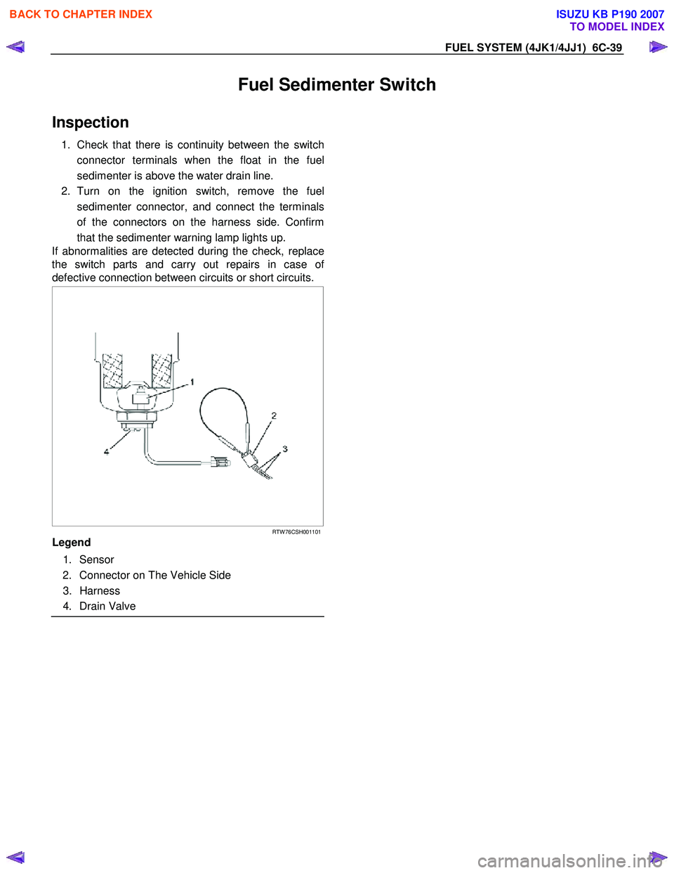
Inspection
1. Check that there is continuity between the switch
connector terminals when the float in the fuel
sedimenter is above the water drain line.
2. Turn on the ignition switch, remove the fuel sedimenter connector, and connect the terminals
of the connectors on the harness side. Confirm
that the sedimenter warning lamp lights up.
If abnormalities are detected during the check, replace
the switch parts and carry out repairs in case o
f
defective connection between circuits or short circuits.
RTW 76CSH001101
Legend
1. Sensor
2. Connector on The Vehicle Side
3. Harness
4. Drain Valve
BACK TO CHAPTER INDEX
TO MODEL INDEX
ISUZU KB P190 2007
Page 1589 of 6020
ENGINE ELECTRICAL (4JK1/4JJ1) 6D-1
SECTION 6D
ENGINE ELECTRICAL
TABLE OF CONTENTS
Charging System ................................................ 6D-2
Servicing Cautions .......................................... 6D-2
Important Generator Components and
Function.......................................................... 6D-2
Troubleshooting .............................................. 6D-5
Diagnosis......................................................... 6D-7
Specifications .................................................. 6D-8
Unit Se rv ic ing (4 JJ 1) ....................................... .... ..6D -9
Disassembly .................................................... 6D-10
Inspection and Repair ..................................... 6D-11 Rotor Assembly ........................................... 6D-11
Stator Coil .................................................... 6D-12
Brushes ....................................................... 6D-12
Rectifier ....................................................... 6D-13
Regulator Assembly..................................... 6D-13
Measuring Procedure .................................. 6D-13
Reassembly..................................................... 6D-14
Final Assembly ................................................ 6D-14
Starter Motor ...................................................... 6D-15 Starting Circuit Diagram .................................. 6D-15
Removal and Installation ................................. 6D-15 Important Operations – Removal................. 6D-15
Important Operations – Installation.............. 6D-15
Disassembly .................................................... 6D-16 Disassembly Steps ...................................... 6D-16
Important Operations ................................... 6D-17
Inspection and Repair ..................................... 6D-20 Armature ...................................................... 6D-20
Yoke............................................................. 6D-21
Brush and Brush Holder .............................. 6D-22
Overrunning Clutch...................................... 6D-22
Bearing ........................................................ 6D-23
Reassembly..................................................... 6D-24 Reassembly Steps ....................................... 6D-24
Important Operations ................................... 6D-25
Inspection After Assembly ........................... 6D-26
Magnetic Switch .............................................. 6D-27
Torque Specifications...................................... 6D-28
Pre-Heating System ........................................... 6D-29 Inspection and Repair ..................................... 6D-29 Visual Check................................................ 6D-29
Glow Relay .................................................. 6D-29
Glow Plug .................................................... 6D-29
BACK TO CHAPTER INDEX
TO MODEL INDEX
ISUZU KB P190 2007
Page 1590 of 6020
6D-2 ENGINE ELECTRICAL (4JK1/4JJ1)
Charging System
Servicing Cautions
• Battery polarity is important. If the battery cables
are reversed, the generator diodes will be
destroyed.
• Do not remove the battery cables or the charging
circuit wiring when the engine is running.
• Confirm that the terminal wires are connected to
the proper terminals by checking the terminal
numbers (the number on the terminal wire and the
terminal must be the same).
• Disconnect the battery negative cable (-) before
inspecting the generator.
• Do not open or close the battery relay switch when
the engine is running.
• Disconnect the battery negative cable (-) when
using external equipment (Quick-Charge) to
charge the battery.
• W hen steam cleaning or washing the engine, do
not allow steam or water to come in direct contact
with the battery and other electrical system
components.
• Be sure to read the item on belt tension
adjustment before beginning the procedure.
Important Generator Components
and Function
• The generator used on 4JK1 engine cannot be
disassembled.
• The generator uses a built-in solid-state IC voltage
regulator. The regulator and other important
components together with their connections are
shown in the illustration.
• The voltage regulator is installed to the rear cove
r
assembly of the generator together with the brush
holder and the rectifier. The generator requires no
additional voltage regulation.
• 9 diodes are connected to the stator coil to convert
AC to DC. The DC voltage is delivered to the
generator output terminal.
BACK TO CHAPTER INDEX
TO MODEL INDEX
ISUZU KB P190 2007
Page 1599 of 6020
ENGINE ELECTRICAL (4JK1/4JJ1) 6D-11
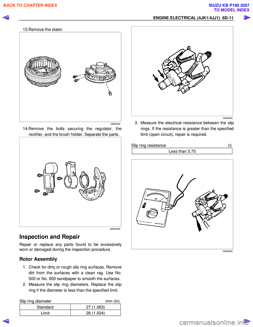
13.Remove the stator.
066RS030
14.Remove the bolts securing the regulator, the
rectifier, and the brush holder. Separate the parts.
066RW 025
Inspection and Repair
Repair or replace any parts found to be excessively
worn or damaged during the inspection procedure.
Rotor Assembly
1. Check for dirty or rough slip ring surfaces. Remove
dirt from the surfaces with a clean rag. Use No.
500 or No. 600 sandpaper to smooth the surfaces.
2. Measure the slip ring diameters. Replace the slip ring if the diameter is less than the specified limit.
Slip ring diameter mm (in)
Standard 27 (1.063)
Limit 26 (1.024)
066RS032
3. Measure the electrical resistance between the slip
rings. If the resistance is greater than the specified
limit (open circuit), repair is required.
Slip ring resistance Ω
Less than 3.75
066RS033
BACK TO CHAPTER INDEX
TO MODEL INDEX
ISUZU KB P190 2007
Page 1603 of 6020
ENGINE ELECTRICAL (4JK1/4JJ1) 6D-15
Starter Motor
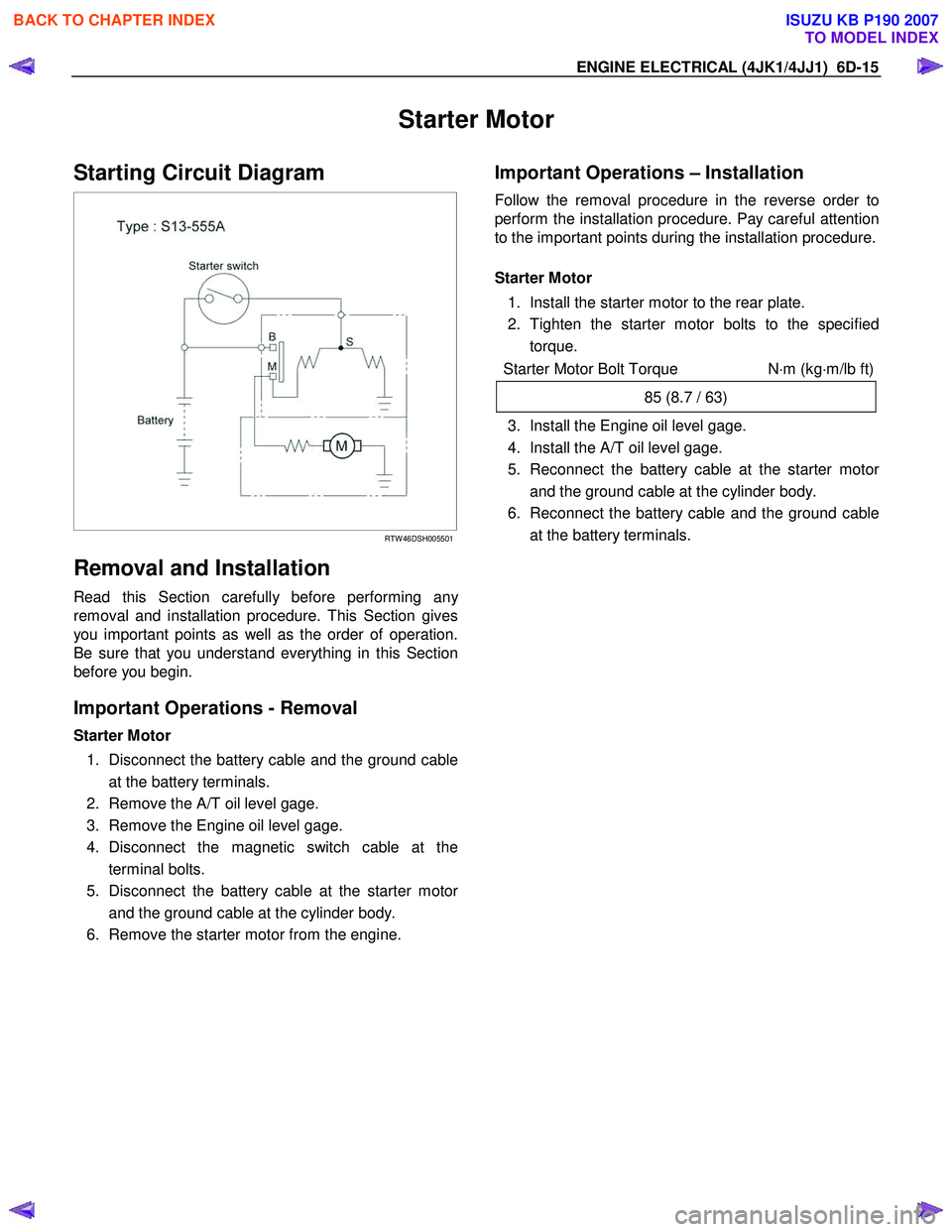
Starting Circuit Diagram
RTW 46DSH005501
Removal and Installation
Read this Section carefully before performing any
removal and installation procedure. This Section gives
you important points as well as the order of operation.
Be sure that you understand everything in this Section
before you begin.
Important Operations - Removal
Starter Motor
1. Disconnect the battery cable and the ground cable at the battery terminals.
2. Remove the A/T oil level gage.
3. Remove the Engine oil level gage.
4. Disconnect the magnetic switch cable at the terminal bolts.
5. Disconnect the battery cable at the starter moto
r
and the ground cable at the cylinder body.
6. Remove the starter motor from the engine.
Important Operations – Installation
Follow the removal procedure in the reverse order to
perform the installation procedure. Pay careful attention
to the important points during the installation procedure.
Starter Motor
1. Install the starter motor to the rear plate.
2. Tighten the starter motor bolts to the specified torque.
Starter Motor Bolt Torque N⋅m (kg ⋅m/lb ft)
85 (8.7 / 63)
3. Install the Engine oil level gage.
4. Install the A/T oil level gage.
5. Reconnect the battery cable at the starter moto
r
and the ground cable at the cylinder body.
6. Reconnect the battery cable and the ground cable at the battery terminals.
BACK TO CHAPTER INDEX
TO MODEL INDEX
ISUZU KB P190 2007