2007 ISUZU KB P190 service indicator
[x] Cancel search: service indicatorPage 1950 of 6020
ENGINE CONTROL SYSTEM (4JK1/4JJ1) 6E-333
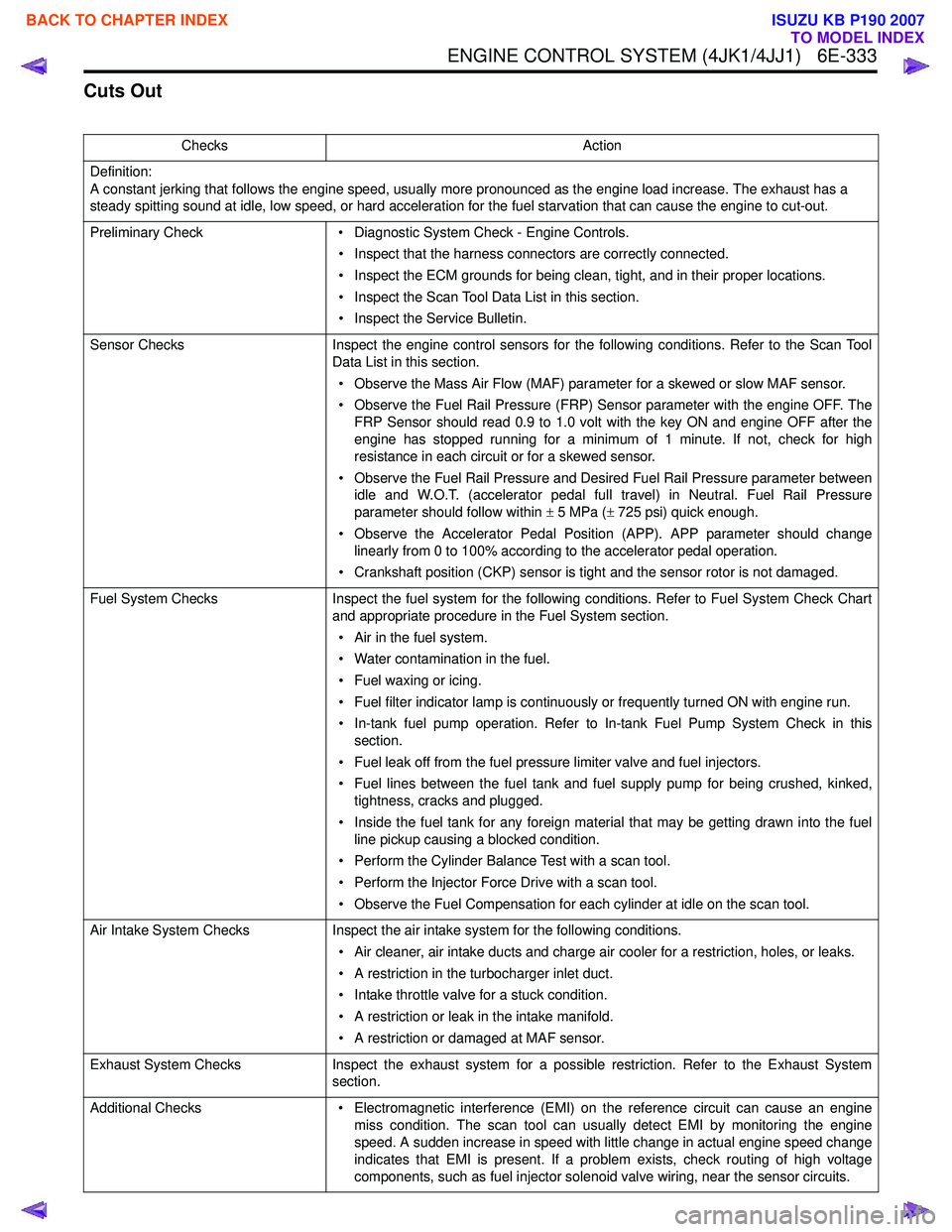
Cuts Out
ChecksAction
Definition:
A constant jerking that follows the engine speed, usually more pronounced as the engine load increase. The exhaust has a
steady spitting sound at idle, low speed, or hard acceleration for the fuel starvation that can cause the engine to cut-out.
Preliminary Check • Diagnostic System Check - Engine Controls.
• Inspect that the harness connectors are correctly connected.
• Inspect the ECM grounds for being clean, tight, and in their proper locations.
• Inspect the Scan Tool Data List in this section.
• Inspect the Service Bulletin.
Sensor Checks Inspect the engine control sensors for the following conditions. Refer to the Scan Tool
Data List in this section.
• Observe the Mass Air Flow (MAF) parameter for a skewed or slow MAF sensor.
• Observe the Fuel Rail Pressure (FRP) Sensor parameter with the engine OFF. The FRP Sensor should read 0.9 to 1.0 volt with the key ON and engine OFF after the
engine has stopped running for a minimum of 1 minute. If not, check for high
resistance in each circuit or for a skewed sensor.
• Observe the Fuel Rail Pressure and Desired Fuel Rail Pressure parameter between idle and W.O.T. (accelerator pedal full travel) in Neutral. Fuel Rail Pressure
parameter should follow within ± 5 MPa ( ± 725 psi) quick enough.
• Observe the Accelerator Pedal Position (APP). APP parameter should change linearly from 0 to 100% according to the accelerator pedal operation.
• Crankshaft position (CKP) sensor is tight and the sensor rotor is not damaged.
Fuel System Checks Inspect the fuel system for the following conditions. Refer to Fuel System Check Chart
and appropriate procedure in the Fuel System section.
• Air in the fuel system.
• Water contamination in the fuel.
• Fuel waxing or icing.
• Fuel filter indicator lamp is continuously or frequently turned ON with engine run.
• In-tank fuel pump operation. Refer to In-tank Fuel Pump System Check in this section.
• Fuel leak off from the fuel pressure limiter valve and fuel injectors.
• Fuel lines between the fuel tank and fuel supply pump for being crushed, kinked, tightness, cracks and plugged.
• Inside the fuel tank for any foreign material that may be getting drawn into the fuel line pickup causing a blocked condition.
• Perform the Cylinder Balance Test with a scan tool.
• Perform the Injector Force Drive with a scan tool.
• Observe the Fuel Compensation for each cylinder at idle on the scan tool.
Air Intake System Checks Inspect the air intake system for the following conditions.
• Air cleaner, air intake ducts and charge air cooler for a restriction, holes, or leaks.
• A restriction in the turbocharger inlet duct.
• Intake throttle valve for a stuck condition.
• A restriction or leak in the intake manifold.
• A restriction or damaged at MAF sensor.
Exhaust System Checks Inspect the exhaust system for a possible restriction. Refer to the Exhaust System
section.
Additional Checks • Electromagnetic interference (EMI) on the reference circuit can cause an engine
miss condition. The scan tool can usually detect EMI by monitoring the engine
speed. A sudden increase in speed with little change in actual engine speed change
indicates that EMI is present. If a problem exists, check routing of high voltage
components, such as fuel injector solenoid valve wiring, near the sensor circuits.
BACK TO CHAPTER INDEX
TO MODEL INDEX
ISUZU KB P190 2007
Page 1951 of 6020
6E-334 ENGINE CONTROL SYSTEM (4JK1/4JJ1)
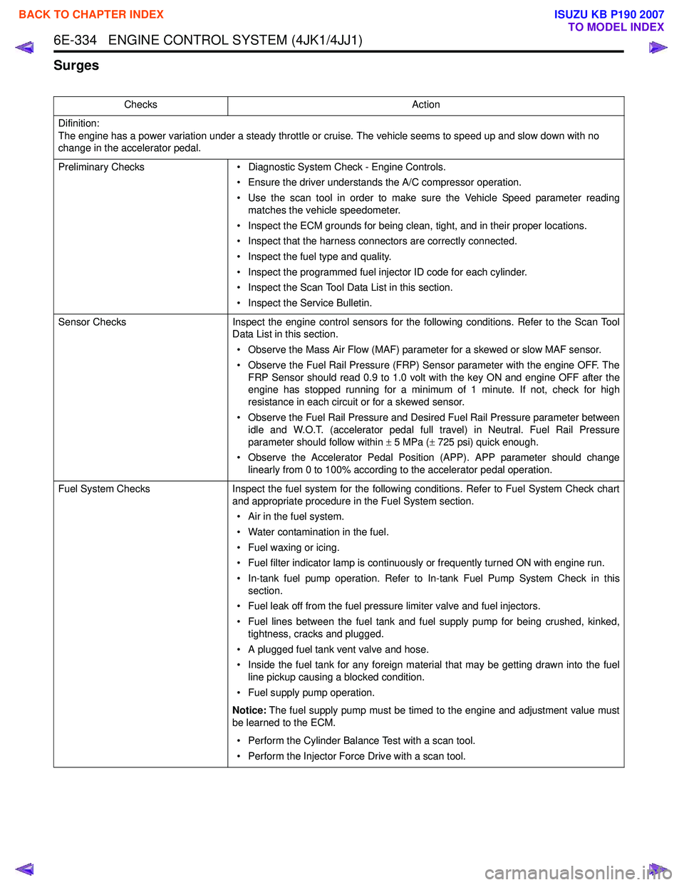
Surges
ChecksAction
Difinition:
The engine has a power variation under a steady throttle or cruise. The vehicle seems to speed up and slow down with no
change in the accelerator pedal.
Preliminary Checks • Diagnostic System Check - Engine Controls.
• Ensure the driver understands the A/C compressor operation.
• Use the scan tool in order to make sure the Vehicle Speed parameter reading matches the vehicle speedometer.
• Inspect the ECM grounds for being clean, tight, and in their proper locations.
• Inspect that the harness connectors are correctly connected.
• Inspect the fuel type and quality.
• Inspect the programmed fuel injector ID code for each cylinder.
• Inspect the Scan Tool Data List in this section.
• Inspect the Service Bulletin.
Sensor Checks Inspect the engine control sensors for the following conditions. Refer to the Scan Tool
Data List in this section.
• Observe the Mass Air Flow (MAF) parameter for a skewed or slow MAF sensor.
• Observe the Fuel Rail Pressure (FRP) Sensor parameter with the engine OFF. The FRP Sensor should read 0.9 to 1.0 volt with the key ON and engine OFF after the
engine has stopped running for a minimum of 1 minute. If not, check for high
resistance in each circuit or for a skewed sensor.
• Observe the Fuel Rail Pressure and Desired Fuel Rail Pressure parameter between idle and W.O.T. (accelerator pedal full travel) in Neutral. Fuel Rail Pressure
parameter should follow within ± 5 MPa ( ± 725 psi) quick enough.
• Observe the Accelerator Pedal Position (APP). APP parameter should change linearly from 0 to 100% according to the accelerator pedal operation.
Fuel System Checks Inspect the fuel system for the following conditions. Refer to Fuel System Check chart
and appropriate procedure in the Fuel System section.
• Air in the fuel system.
• Water contamination in the fuel.
• Fuel waxing or icing.
• Fuel filter indicator lamp is continuously or frequently turned ON with engine run.
• In-tank fuel pump operation. Refer to In-tank Fuel Pump System Check in this section.
• Fuel leak off from the fuel pressure limiter valve and fuel injectors.
• Fuel lines between the fuel tank and fuel supply pump for being crushed, kinked, tightness, cracks and plugged.
• A plugged fuel tank vent valve and hose.
• Inside the fuel tank for any foreign material that may be getting drawn into the fuel line pickup causing a blocked condition.
• Fuel supply pump operation.
Notice: The fuel supply pump must be timed to the engine and adjustment value must
be learned to the ECM.
• Perform the Cylinder Balance Test with a scan tool.
• Perform the Injector Force Drive with a scan tool.
BACK TO CHAPTER INDEX
TO MODEL INDEX
ISUZU KB P190 2007
Page 1970 of 6020
ENGINE CONTROL SYSTEM (4JK1/4JJ1) 6E-353
Description and Operation
Engine Control Module (ECM) Description
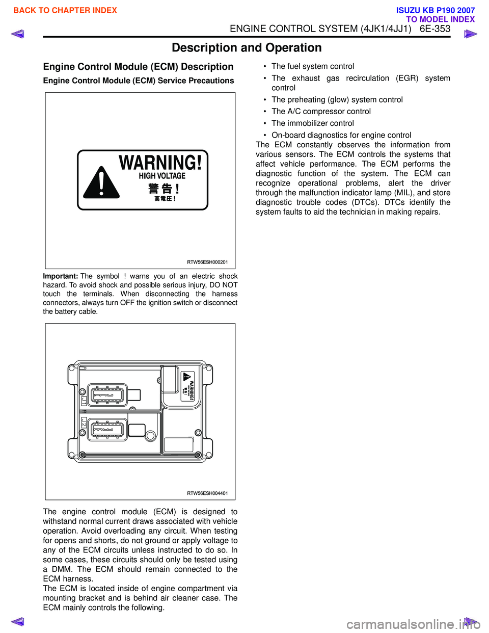
Engine Control Module (ECM) Service Precautions
Important:The symbol ! warns you of an electric shock
hazard. To avoid shock and possible serious injury, DO NOT
touch the terminals. When disconnecting the harness
connectors, always turn OFF the ignition switch or disconnect
the battery cable.
The engine control module (ECM) is designed to
withstand normal current draws associated with vehicle
operation. Avoid overloading any circuit. When testing
for opens and shorts, do not ground or apply voltage to
any of the ECM circuits unless instructed to do so. In
some cases, these circuits should only be tested using
a DMM. The ECM should remain connected to the
ECM harness.
The ECM is located inside of engine compartment via
mounting bracket and is behind air cleaner case. The
ECM mainly controls the following. • The fuel system control
• The exhaust gas recirculation (EGR) system control
• The preheating (glow) system control
• The A/C compressor control
• The immobilizer control
• On-board diagnostics for engine control
The ECM constantly observes the information from
various sensors. The ECM controls the systems that
affect vehicle performance. The ECM performs the
diagnostic function of the system. The ECM can
recognize operational problems, alert the driver
through the malfunction indicator lamp (MIL), and store
diagnostic trouble codes (DTCs). DTCs identify the
system faults to aid the technician in making repairs.
RTW56ESH000201
RTW56ESH004401
BACK TO CHAPTER INDEX
TO MODEL INDEX
ISUZU KB P190 2007
Page 1971 of 6020
6E-354 ENGINE CONTROL SYSTEM (4JK1/4JJ1)
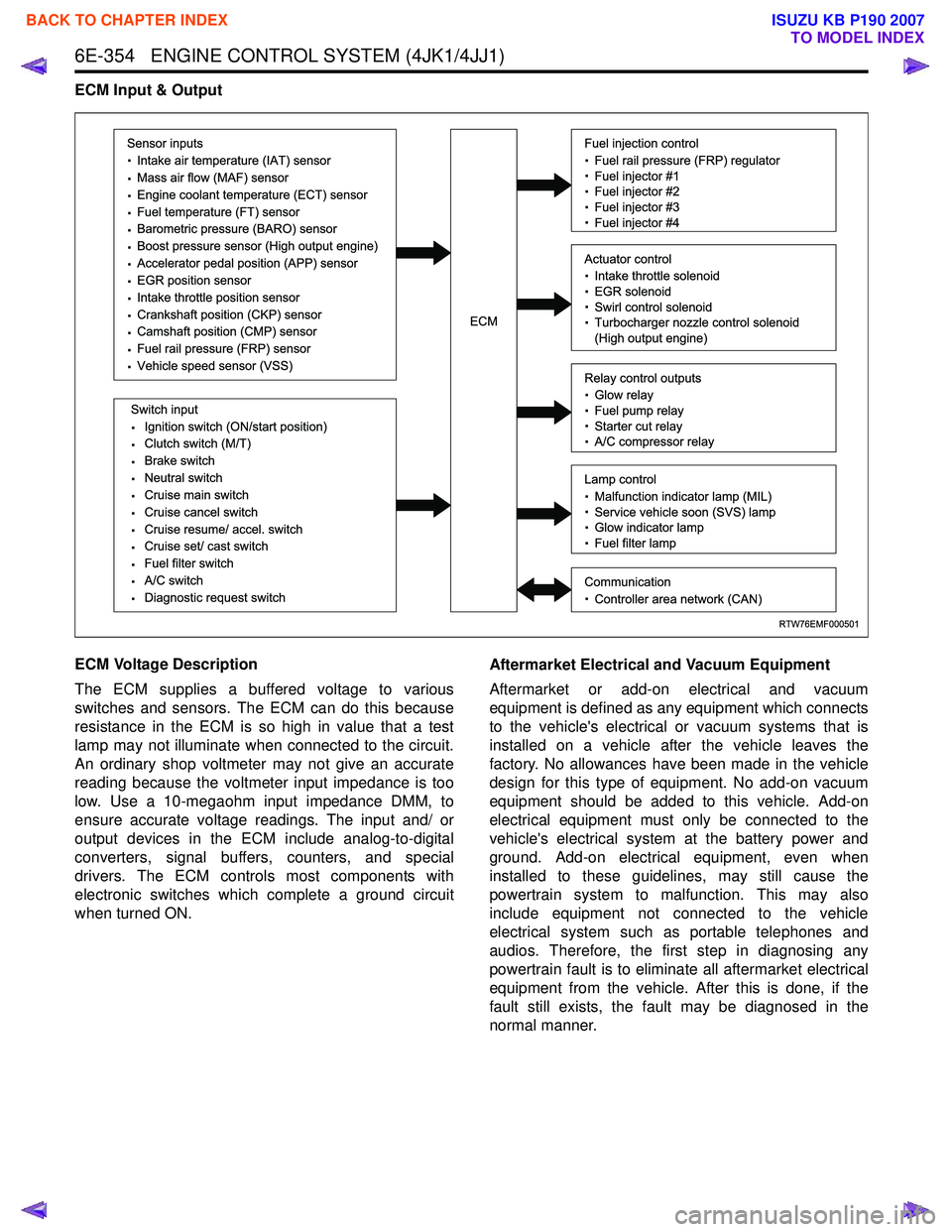
ECM Input & Output
ECM Voltage Description
The ECM supplies a buffered voltage to various
switches and sensors. The ECM can do this because
resistance in the ECM is so high in value that a test
lamp may not illuminate when connected to the circuit.
An ordinary shop voltmeter may not give an accurate
reading because the voltmeter input impedance is too
low. Use a 10-megaohm input impedance DMM, to
ensure accurate voltage readings. The input and/ or
output devices in the ECM include analog-to-digital
converters, signal buffers, counters, and special
drivers. The ECM controls most components with
electronic switches which complete a ground circuit
when turned ON. Aftermarket Electrical and Vacuum Equipment
Aftermarket or add-on electrical and vacuum
equipment is defined as any equipment which connects
to the vehicle's electrical or vacuum systems that is
installed on a vehicle after the vehicle leaves the
factory. No allowances have been made in the vehicle
design for this type of equipment. No add-on vacuum
equipment should be added to this vehicle. Add-on
electrical equipment must only be connected to the
vehicle's electrical system at the battery power and
ground. Add-on electrical equipment, even when
installed to these guidelines, may still cause the
powertrain system to malfunction. This may also
include equipment not connected to the vehicle
electrical system such as portable telephones and
audios. Therefore, the first step in diagnosing any
powertrain fault is to eliminate all aftermarket electrical
equipment from the vehicle. After this is done, if the
fault still exists, the fault may be diagnosed in the
normal manner.
RTW76EMF000501
Sensor inputs
· Intake air temperature (IAT) sensor
· Mass air flow (MAF) sensor
· Engine coolant temperature (ECT) sensor
· Fuel temperature (FT) sensor
· Barometric pressure (BARO) sensor
· Boost pressure sensor (High output engine)
· Accelerator pedal position (APP) sensor
· EGR position sensor
· Intake throttle position sensor
· Crankshaft position (CKP) sensor
· Camshaft position (CMP) sensor
· Fuel rail pressure (FRP) sensor
· Vehicle speed sensor (VSS)
Switch input
· Ignition switch (ON/start position)
· Clutch switch (M/T)
· Brake switch
· Neutral switch
· Cruise main switch
· Cruise cancel switch
· Cruise resume/ accel. switch
· Cruise set/ cast switch
· Fuel filter switch
· A/C switch
· Diagnostic request switch
Fuel injection control
· Fuel rail pressure (FRP) regulator
· Fuel injector #1
· Fuel injector #2
· Fuel injector #3
· Fuel injector #4
Relay control outputs
· Glow relay
· Fuel pump relay
· Starter cut relay
· A/C compressor relay
Lamp control
· Malfunction indicator lamp (MIL)
· Service vehicle soon (SVS) lamp
· Glow indicator lamp
· Fuel filter lamp
Communication
· Controller area network (CAN)
Actuator control
· Intake throttle solenoid
· EGR solenoid
· Swirl control solenoid
· Turbocharger nozzle control solenoid
(High output engine)ECM
BACK TO CHAPTER INDEX
TO MODEL INDEX
ISUZU KB P190 2007
Page 1972 of 6020
ENGINE CONTROL SYSTEM (4JK1/4JJ1) 6E-355
Electrostatic Discharge Damage
Electronic components used in the ECM are often
designed to carry very low voltage. Electronic
components are susceptible to damage caused by
electrostatic discharge. By comparison, as much as
4,000 volts may be needed for a person to feel even
the zap of a static discharge. There are several ways
for a person to become statically charged. The most
common methods of charging are by friction and
induction.
• An example of charging by friction is a person sliding across a vehicle seat.
Important: To prevent possible electrostatic discharge
damage, follow these guidelines:
• Do not touch the ECM connector pins or soldered components on the ECM circuit board.
• Do not open the replacement part package until the part is ready to be installed.
• Before removing the part from the package, ground the package to a known good ground on
the vehicle.
• If the part has been handled while sliding across the seat, while sitting down from a standing
position, or while walking a distance, touch a
known good ground before installing the part.
• Charge by induction occurs when a person with well insulated shoes stands near a highly charged
object and momentarily touches ground. Charges
of the same polarity are drained off leaving the
person highly charged with opposite polarity.
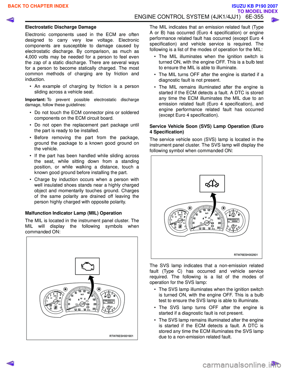
Malfunction Indicator Lamp (MIL) Operation
The MIL is located in the instrument panel cluster. The
MIL will display the following symbols when
commanded ON: The MIL indicates that an emission related fault (Type
A or B) has occurred (Euro 4 specification) or engine
performance related fault has occurred (except Euro 4
specification) and vehicle service is required. The
following is a list of the modes of operation for the MIL:
• The MIL illuminates when the ignition switch is turned ON, with the engine OFF. This is a bulb test
to ensure the MIL is able to illuminate.
• The MIL turns OFF after the engine is started if a diagnostic fault is not present.
• The MIL remains illuminated after the engine is started if the ECM detects a fault. A DTC is stored
any time the ECM illuminates the MIL due to an
emission related fault (Euro 4 specification), and
engine performance related fault has occurred
(except Euro 4 specification).
Service Vehicle Soon (SVS) Lamp Operation (Euro
4 Specification)
The service vehicle soon (SVS) lamp is located in the
instrument panel cluster. The SVS lamp will display the
following symbol when commanded ON:
The SVS lamp indicates that a non-emission related
fault (Type C) has occurred and vehicle service
required. The following is a list of the modes of
operation for the SVS lamp:
• The SVS lamp illuminates when the ignition switch is turned ON, with the engine OFF. This is a bulb
test to ensure the SVS lamp is able to illuminate.
• The SVS lamp turns OFF after the engine is started if a diagnostic fault is not present.
• The SVS lamp remains illuminated after the engine is started if the ECM detects a fault. A DTC is
stored any time the ECM illuminates the SVS lamp
due to a non-emission related fault.
RTW76ESH001901
RTW76ESH002901
BACK TO CHAPTER INDEX
TO MODEL INDEX
ISUZU KB P190 2007
Page 2402 of 6020
6E–232 ENGINE DRIVEABILITY AND EMISSIONS
SYMPTOM DIAGNOSIS
PRELIMINARY CHECKS
Before using this section, perform the “On-Board
Diagnostic (OBD) System Check” and verify all of the
following items:
• The engine control module (ECM) and malfunction indicator lamp (MIL = Check Engine Lamp) are
operating correctly.
• There are no Diagnostic Trouble Code(s) stored.
• Tech 2 data is within normal operating range. Refer to Typical Scan Data Values.
• Verify the customer complaint and locate the correct symptom in the table of contents. Perform the
procedure included in the symptom chart.
VISUAL/PHYSICAL CHECK
Several of the symptom procedures call for a careful
visual/physical check. This can lead to correcting a
problem without further checks and can save valuable
time. This check should include the following items:
• ECM grounds for cleanliness, tightness and proper location.
• Vacuum hoses for splits, kinks, and proper connection, shown on the “Emission Control System
Schematics”. Check thoroughly for any type of leak or
restriction.
• Air intake ducts for collapsed or damaged areas.
• Air leaks at throttle body mounting area, manifold absolute pressure (MAP) sensor and intake manifold
sealing surfaces.
• Ignition wires for cracking, harness, and carbon tracking.
• Wiring for proper connections, pinches and cuts.
INTERMITTENT
Important: An intermittent problem may or may not turn
on the malfunction indicator lamp (MIL) or store a
Diagnostic Trouble Code. Do NOT use the Diagnostic
Trouble Code (DTC) charts for intermittent problems.
The fault must be present to locate the problem.
Most intermittent problems are cased by faulty electrical
connections or wiring. Perform a careful visual/physical
check for the following conditions.
• Poor mating of the connector halves or a terminal not fully seated in the connector (backed out).
• Improperly formed or damaged terminal.
• All connector terminals in the problem circuit should be carefully checked for proper contact tension.
• Poor terminal-to-wire connection. This requires removing the terminal form the connector body to
check.
• Ignition coils shorted to ground and arcing at ignition wires or plugs. • MIL (Check Engine Lamp) wire to ECM shorted to
ground.
• Poor ECM grounds. Refer to the ECM wiring diagrams.
Road test the vehicle with a Digital Multimeter
connected to a suspected circuit. An abnormal voltage
when the malfunction occurs is a good indication that
there is a fault in the circuit being monitored.
Using Tech 2 to help detect intermittent conditions. The
Tech 2 has several features that can be used to located
an intermittent condition.
An intermittent MIL (Check Engine Lamp) with no stored
Diagnostic Trouble Code may be caused by the
following:
• Ignition coil shorted to ground and arcing at ignition wires or plugs.
• MIL (Check Engine Lamp) wire to ECM short to ground.
• Poor ECM grounds. Refer to the ECM wiring diagrams.
Check for improper installation of electrical options such
as light, cellular phones, etc. Check all wires from ECM
to the ignition control module for poor connections.
Check for an open diode across the A/C compressor
clutch and check for other open diodes (refer to wiring
diagrams in Electrical Diagnosis).
If problem has not been found, refer to ECM connector
symptom tables.
• Check the “Broadcast Code” of the ECM, and compare it with the latest Isuzu service bulletins and/
or Isuzu EEPROM reprogramming equipment to
determine if an update to the ECM’s reprogrammable
memory has been released.
To check the “Broadcast Code”, connect the Tech 2,
then look for “ID info.” then select “Broadcast Code”.
This should display a 4 character code, such as “XBYA”
(example only).
This identifies the contents of the reprogrammable
software and calibration contained in the ECM.
If the “Broadcast Code” is not the most current
available, it is advisable to reprogram the ECM’s
EEPROM memory, which may either help identify a
hard-to find problem or may fix the problem.
The Service Programming System (SPS) will not allow
incorrect software programming or incorrect calibration
changes.
BACK TO CHAPTER INDEX
TO MODEL INDEX
ISUZU KB P190 2007
Page 2482 of 6020
Engine Mechanical – V6 Page 6A1–3
Definition .......................................................................................................................................................... 50
Diagnostic Aids................................................................................................................................................. 50
Test Description ............................................................................................................... ................................ 50
Diagnostic Table............................................................................................................................................... 51
Drive Belt Excessive Wear ...................................................................................................... ............................ 51
Definition .......................................................................................................................................................... 51
Diagnostic Aids................................................................................................................................................. 52
Test Description ............................................................................................................... ................................ 52
Diagnostic Table............................................................................................................................................... 52
Accessory Drive Belt Tensioner Diagnosis ....................................................................................... ................ 52
Diagnostic Table............................................................................................................................................... 52
3 Minor Service Operations ....................................................................................................... .............53
3.1 Engine Oil ............................................................................................................................................................. 54
Check .................................................................................................................................................................... 54
Replace ........................................................................................................................ ......................................... 54
Pressure Check ................................................................................................................. ................................... 55
3.2 Oil Filter Cartridge ............................................................................................................................................... 56
Replace ................................................................................................................................................................. 56
3.3 Oil Filter Adaptor............................................................................................................. ..................................... 57
Remove ................................................................................................................................................................. 57
Reinstall ................................................................................................................................................................ 57
3.4 Oil Level Indicator Tube ....................................................................................................... ............................... 58
Remove ............................................................................................................................................................ 58
Reinstall ........................................................................................................................................................... 58
3.5 Accessory Drive Belt ........................................................................................................... ................................ 59
RWD Vehicle ......................................................................................................................................................... 59
Remove ............................................................................................................................................................ 59
Reinstall ........................................................................................................................................................... 59
3.6 Accessory Drive Belt Idler Pulley .............................................................................................. ......................... 60
Remove ............................................................................................................................................................ 60
Reinstall ........................................................................................................................................................... 60
3.7 Accessory Drive Belt Tensioner Assembly ........................................................................................ ............... 61
Remove ............................................................................................................................................................ 61
Reinstall ........................................................................................................................................................... 61
3.8 Power Steering Pump Bracket .................................................................................................... ........................ 62
Remove ................................................................................................................................................................. 62
Reinstall ................................................................................................................................................................ 62
3.9 Upper Intake Manifold.......................................................................................................... ................................ 62
Remove ................................................................................................................................................................. 63
Disassemble ......................................................................................................................................................... 66
Clean ..................................................................................................................................................................... 66
Inspect .................................................................................................................................................................. 66
Reassemble .......................................................................................................................................................... 67
Reinstall ...................................................................................................................... .......................................... 67
3.10 Intake Manifold Assembly – Complete............................................................................................ ................... 68
Remove ................................................................................................................................................................. 68
Disassemble ......................................................................................................................................................... 72
Clean ..................................................................................................................................................................... 73
Inspect .................................................................................................................................................................. 73
Reassemble .......................................................................................................................................................... 74
Reinstall ...................................................................................................................... .......................................... 74
3.11 Exhaust Manifold Assembly ...................................................................................................... ......................... 75
Remove ................................................................................................................................................................. 75
Inspect .................................................................................................................................................................. 77
Reinstall ................................................................................................................................................................ 77
3.12 Camshaft Cover ................................................................................................................. .................................. 79
Remove ................................................................................................................................................................. 79
Clean and Inspect .............................................................................................................. .................................. 81
BACK TO CHAPTER INDEX
TO MODEL INDEX
ISUZU KB P190 2007
Page 2518 of 6020

Engine Mechanical – V6 Page 6A1–39
2.16 Cylinder Leakage Test
A leakage test may be performed to measure cylinder/combustion chamber leakage. High cylinder leakage may indicate
one or more of the following:
• worn or burnt valves,
• broken valve springs,
• stuck valve lifters,
• incorrect valve lash/adjustment,
• damaged piston,
• worn piston rings,
• worn or scored cylinder bore,
• damaged cylinder head gasket,
• cracked or damaged cylinder head, or
• cracked or damaged engine block.
1 Disconnect the battery ground negative cable.
2 Remove the spark plugs from all cylinders, refer to 6C1-3 Engine Management – V6 – Service Operations.
3 Rotate the crankshaft to place the piston in the cylinder being tested at top dead centre (TDC) of the compression stroke.
4 Install a commercially available cylinder head leak down tester into the spark plug hole.
NOTE
If required, hold the crankshaft balancer bolt to
prevent the engine from rotating.
5 Apply shop air pressure to the cylinder head leak down tester and adjust according to the manufacturers instructions.
6 Record the cylinder leakage value. Cylinder leakage that exceeds 25 percent is considered excessive and may require component service. In excessive leakage situations, inspect for the following conditions:
• air leakage sounds at the throttle body or air inlet duct that may indicate a worn or burnt intake valve or a
broken valve spring,
• air leakage sounds at the exhaust system tailpipe that may indicate a worn or burnt exhaust valve or a broken
valve spring,
• air leakage sounds from the crankcase, oil level indicator tube, or oil fill tube that may indicate worn piston
rings, a damaged piston, a worn or scored cylinder bore, a damaged engine block or a damaged cylinder
head, or
• air bubbles in the cooling system may indicate a damaged cylinder head or a damaged cylinder head gasket.
7 Perform the leakage test on the remaining cylinders and record the values.
2.17 Engine Oil Consumption Diagnosis
Definition
Excessive oil consumption (not due to leaks) is the use of 3 litres or more of engine oil within 10,000 kilometres. Prior to
performing oil pressure testing, a preliminary inspection of the vehicle should be performed. During the preliminary visual
inspection, the following likely causes of excessive oil usage should be investigated.
Cause Correction
External oil leaks. Refer to 2.18 Engine Oil Leak Diagnosis.
Incorrect oil level or reading of the oil level indicator. Check for the correct oil level, refer to 3.1 Engine Oil.
Incorrect oil viscosity. Replace the engine oil, using the recommended SAE grade
of engine oil, refer to 3.1 Engine Oil.
Continuous high-speed driving or severe usage. Service vehicle more frequently, refer to 0B Lubrication and
Service.
Crankcase ventilation system restricted or malfunctioning. Repair or replace crankcase ventilation system components as required, refer to 6C1-3 Engine Management – V6 –
Service Operations.
BACK TO CHAPTER INDEX
TO MODEL INDEX
ISUZU KB P190 2007