2007 ISUZU KB P190 service indicator
[x] Cancel search: service indicatorPage 1661 of 6020
6E-44 ENGINE CONTROL SYSTEM (4JK1/4JJ1)
Diagnostic Starting Point - Engine Controls
Begin the system diagnosis with Diagnostic System
Check - Engine Controls. The Diagnostic System
Check - Engine Controls will provide the following
information:
• The identification of the control modules which command the system.
• The ability of the control modules to communicate through the serial data circuit.
• The identification of any stored diagnostic trouble codes (DTCs) and the their statuses.
The use of the Diagnostic System Check - Engine
Controls will identify the correct procedure for
diagnosing the system and where the procedure is
located.
Important: Engine Control System Check Sheet must
be used to verify the complaint vehicle, you need to
know the correct (normal) operating behavior of the
system and verify that the customer complaint is a valid
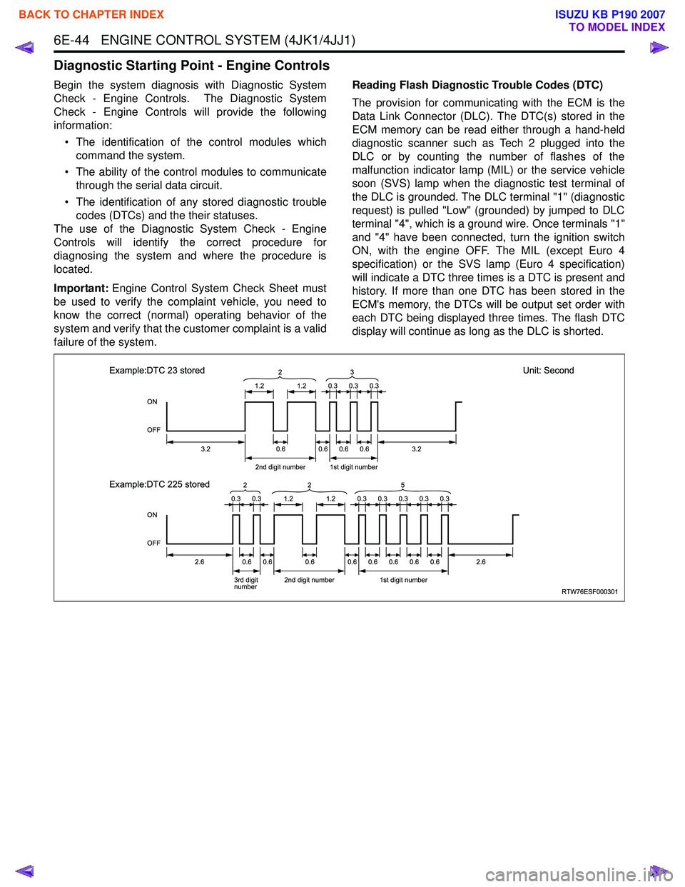
failure of the system. Reading Flash Diagnostic Trouble Codes (DTC)
The provision for communicating with the ECM is the
Data Link Connector (DLC). The DTC(s) stored in the
ECM memory can be read either through a hand-held
diagnostic scanner such as Tech 2 plugged into the
DLC or by counting the number of flashes of the
malfunction indicator lamp (MIL) or the service vehicle
soon (SVS) lamp when the diagnostic test terminal of
the DLC is grounded. The DLC terminal "1" (diagnostic
request) is pulled "Low" (grounded) by jumped to DLC
terminal "4", which is a ground wire. Once terminals "1"
and "4" have been connected, turn the ignition switch
ON, with the engine OFF. The MIL (except Euro 4
specification) or the SVS lamp (Euro 4 specification)
will indicate a DTC three times is a DTC is present and
history. If more than one DTC has been stored in the
ECM's memory, the DTCs will be output set order with
each DTC being displayed three times. The flash DTC
display will continue as long as the DLC is shorted.
RTW76ESF000301
ON
OFF
ON
OFF
1.2
3.2
2.62.6
2nd digit number1st digit number
3.20.6 2
1.2
0.60.60.6
0.30.30.3
0.30.30.30.30.3
Example:DTC 23 stored
Unit: Second
Example:DTC 225 stored
3rd digit
number 2nd digit number1st digit number
0.60.60.60.60.60.60.60.6
3
0.30.31.21.2
2
25
BACK TO CHAPTER INDEX
TO MODEL INDEX
ISUZU KB P190 2007
Page 1666 of 6020
ENGINE CONTROL SYSTEM (4JK1/4JJ1) 6E-49
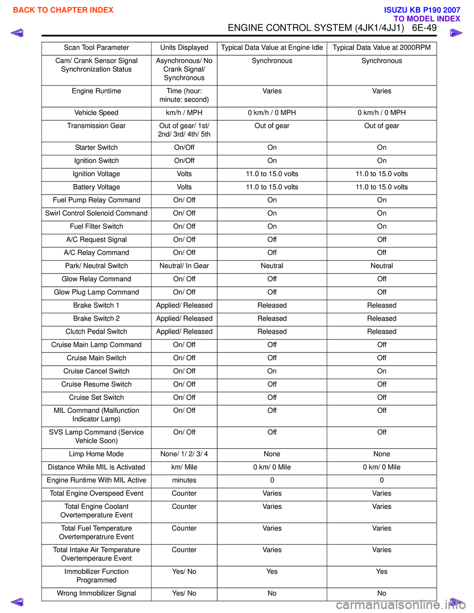
Cam/ Crank Sensor Signal Synchronization Status Asynchronous/ No
Crank Signal/ Synchronous Synchronous Synchronous
Engine Runtime Time (hour: minute: second) Va r i e s
Va r i e s
Vehicle Speed km/h / MPH0 km/h / 0 MPH 0 km/h / 0 MPH
Transmission Gear Out of gear/ 1st/ 2nd/ 3rd/ 4th/ 5th Out of gear
Out of gear
Starter Switch On/OffOn On
Ignition Switch On/OffOn On
Ignition Voltage Volts11.0 to 15.0 volts 11.0 to 15.0 volts
Battery Voltage Volts11.0 to 15.0 volts 11.0 to 15.0 volts
Fuel Pump Relay Command On/ Off OnOn
Swirl Control Solenoid Command On/ Off OnOn
Fuel Filter Switch On/ OffOn On
A/C Request Signal On/ OffOff Off
A/C Relay Command On/ OffOff Off
Park/ Neutral Switch Neutral/ In Gear NeutralNeutral
Glow Relay Command On/ OffOff Off
Glow Plug Lamp Command On/ Off OffOff
Brake Switch 1 Applied/ Released Released Released
Brake Switch 2 Applied/ Released Released Released
Clutch Pedal Switch Applied/ Released ReleasedReleased
Cruise Main Lamp Command On/ Off OffOff
Cruise Main Switch On/ OffOff Off
Cruise Cancel Switch On/ OffOn On
Cruise Resume Switch On/ OffOff Off
Cruise Set Switch On/ OffOff Off
MIL Command (Malfunction Indicator Lamp) On/ Off
Off Off
SVS Lamp Command (Service Vehicle Soon) On/ Off
Off Off
Limp Home Mode None/ 1/ 2/ 3/ 4 None None
Distance While MIL is Activated km/ Mile 0 km/ 0 Mile0 km/ 0 Mile
Engine Runtime With MIL Active minutes 00
Total Engine Overspeed Event Counter VariesVaries
Total Engine Coolant
Overtemperature Event Counter
Varies Varies
Total Fuel Temperature
Overtemperatrure Event Counter
Varies Varies
Total Intake Air Temperature Overtemperaure Event Counter
Varies Varies
Immobilizer Function Programmed Ye s / N o
Ye s Ye s
Wrong Immobilizer Signal Yes/ NoNo No
Scan Tool Parameter Units Displayed Typical Data Value at Engine Idle Typical Data Value at 2000RPM
BACK TO CHAPTER INDEX
TO MODEL INDEX
ISUZU KB P190 2007
Page 1671 of 6020
6E-54 ENGINE CONTROL SYSTEM (4JK1/4JJ1)
Cruise Cancel Switch
This parameter displays the input state of the cruise
cancel switch to the ECM. When the Cruise Cancel
switch is applied, the scan tool displays Off.
Cruise Resume Switch
This parameter displays the input state of the cruise
resume/accel. switch to the ECM. When the Cruise
Resume/Accel. switch is applied, the scan tool displays
On.
Cruise Set Switch
This parameter displays the input state of the cruise
set/coast switch to the ECM. When the Cruise Set/
Coast switch is pushed, the scan tool displays On.
MIL Command (Malfunction Indicator Lamp)
This parameter displays the commanded state of the
malfunction indicator lamp (MIL) control circuit. The
MIL should be On when the scan tool indicates
command On. The MIL should be Off when the scan
tool indicates command Off.
SVS Lamp Command (Service Vehicle Soon)
This parameter displays the commanded state of the
service vehicle soon (SVS) lamp control circuit. The
SVS lamp should be On when the scan tool indicates
command On. The SVS lamp should be Off when the
scan tool indicates command Off.
Limp Home Mode
This parameter indicates the state of the limp-home
mode. None indicates limp-home mode is not applied.
1, 2, 3 and 4 indicates fuel injection quantity reduction
is applied. 2 or higher number inhibits pilot injection. If 4
is indicated, engine running will be stopped when the
vehicle speed is less than 5 km/h (3 MPH) for 5
seconds.
Distance While MIL is Activated
This parameter displays the mileage since the
malfunction indicator lamp (MIL) is turned ON.
Engine Runtime With MIL Active
This parameter displays the engine run time elapsed
since the malfunction indicator lamp (MIL) is turned
ON. The scan tool will display the time in minutes.
Total Engine Overspeed Event
This parameter indicates counter of engine overspeed
event. Counter will be zero if any DTC is cleared.
Total Engine Coolant Overtemperature Event
This parameter indicates counter of engine overheat
event. The counter is active if engine coolant is over
11 0 °C (230 °F). Counter will be zero if any DTC is
cleared. Total Fuel Temperature Overtemperature Event
This parameter indicates counter of fuel temperature
excessively high condition. The counter is active if fuel
temperature is over 95 °C (203 °F). Counter will be zero
if any DTC is cleared.
Total Intake Air Temperature Overtemperature
Event
This parameter indicates counter of intake air
temperature excessively high condition. The counter is
active if intake air temperature is over 55 °C (131 °F).
Counter will be zero if any DTC is cleared.
Immobilizer Function Programmed
This parameter displays the state of the immobilizer
function programming in the ECM. The scan tool will
display Yes or No. Yes indicates the immobilizer
security information is correctly programmed in the
ECM. No indicates the ECM is not programmed or
ECM is reset.
Wrong Immobilizer Signal
This parameter displays the input state of the received
response signal to the ECM. When the ECM received
wrong response signal from the immobilizer control unit
(ICU), the scan tool displays Yes.
Immobilizer Signal
This parameter displays the input state of the response
signal to the ECM. When the ECM received any
response signal from the immobilizer control unit (ICU),
the scan tool displays Yes.
Security Wait Time
This parameter displays the security wait time length in
the ECM. Inactive indicates not in security wait time.
Time indicates under security wait time. This wait time
stage will prevent any further attempts to enter the
security code until the wait time has elapsed. The wait
time will increase each time an incorrect security code
is entered. Note that this parameter is not count
downed. It keeps displaying the same time until that
wait time has elapsed. The ignition switch must be kept
at ON position during the wait time period.
BACK TO CHAPTER INDEX
TO MODEL INDEX
ISUZU KB P190 2007
Page 1672 of 6020

ENGINE CONTROL SYSTEM (4JK1/4JJ1) 6E-55
Scan Tool Output Controls
Scan Tool Output ControlDescriptions
Fuel Supply Pump Learn Resetting The purpose of this test to reset the fuel supply pump adjustment value.
Important: The fuel supply pump relearn procedure must be done when the fuel supply
pump or engine is replaced, or an ECM from another vehicle is installed. Refer to Fuel
Supply Pump Replacement.
Fuel Pressure Control The purpose of this test is for checking whether the fuel rail pressure is changing when
commanded within 30 to 80MPa (4,350 to 11,600psi) when commanded. Faulty fuel supply
pump, fuel rail pressure (FRP) regulator, pressure limiter valve or other fuel lines could be
considered if the differential fuel rail pressure is large.
Pilot Injection Control The purpose of this test is for checking whether the pilot fuel injection is operated when it is
commanded to ON/ OFF. Faulty injector(s) could be considered if engine noise does not
change when commanded OFF.
Injection Timing Control The purpose of this test is for checking whether the main injection timing is changing when
commanded Retard/ Advance within -5 to 5 °CA.
Injector Force Drive The purpose of this test is for checking whether the fuel injector is correctly operating when
commanded ON. Faulty injector(s) could be considered if it does not create a clicking noise
(solenoid operating noise), contains an interrupted noise or has abnormal noise when
commanded ON.
Cylinder Balance Test The purpose of this test is for checking whether the fuel injector is operating when
commanded ON/ OFF. Faulty injector(s) could be considered if engine does not change
speed when commanded OFF.
Intake Throttle Solenoid Control The purpose of this test is for checking whether the intake throttle valve is correctly moved
with command. Restricted valve movement by foreign materials, excessive deposits or a
faulty valve could be considered if the position difference is large.
EGR Solenoid Control The purpose of this test is for checking whether the EGR valve is correctly moved with
command. Restricted valve movement by foreign materials, excessive deposits or a faulty
valve could be considered if the position difference is large.
Swirl Control Solenoid Control The purpose of this test is for checking whether the swirl control solenoid is operating when
commanded ON. Faulty circuit(s) or a faulty solenoid could be considered if not energizing
when commanded ON.
Turbocharger Solenoid Control The purpose of this test is for checking whether the turbocharger nozzle control actuator is
correctly moved with command. Restricted actuator movement by foreign materials,
excessive deposits, misrouted vacuum hoses, a faulty solenoid or a faulty actuator could be
considered if the actuator is not moved correctly.
Glow Relay Control The purpose of this test is for checking whether the glow relay is operating when
commanded ON. Faulty circuit(s) or a faulty glow relay could be considered if not energizing
when commanded ON.
Glow Plug Lamp Control The purpose of this test is for checking whether the glow indicator lamp is operating when
commanded ON. Faulty circuit(s) or an open circuit could be considered when not operating
when commanded ON.
Malfunction Indicator Lamp (MIL) Control The purpose of this test is for checking whether the MIL is operating when commanded ON.
Faulty circuit(s) or an open circuit could be considered when not operating when
commanded ON.
Service Vehicle Soon (SVS) Lamp Control The purpose of this test is for checking whether the SVS lamp is operating when
commanded ON. Faulty circuit(s) or an open circuit could be considered when not operating
when commanded ON.
Cruise Main Lamp Control The purpose of this test is for checking whether the cruise main lamp is operating when
commanded ON. Faulty circuit(s) or an open circuit could be considered when not operating
when commanded ON.
Cruise Set Lamp Control The purpose of this test is for checking whether the cruise set lamp is operating when
commanded ON. Faulty circuit(s) or an open circuit could be considered when not operating
when commanded ON.
BACK TO CHAPTER INDEX
TO MODEL INDEX
ISUZU KB P190 2007
Page 1823 of 6020
6E-206 ENGINE CONTROL SYSTEM (4JK1/4JJ1)
DTC P0650 (Flash Code 77)
Circuit Description
The malfunction indicator lamp (MIL) is located on the
instrument panel (IP) cluster. The MIL informs the
driver that an emission system fault has occurred and
that the engine control system requires service.
The ECM monitors the MIL control circuit for conditions
that are incorrect for the commanded state of the MIL.
For example, a failure condition exists if the ECM
detects low voltage when the MIL is commanded OFF,
or high voltage when the MIL is commanded ON. If the
ECM detects an improper voltage level on the control
circuit, this DTC will set.
Condition for Running the DTC • The ignition voltage is more than 9 volts.
• The ignition switch is ON.
Condition for Setting the DTC
Either of following condition is met: • The ECM detects a low voltage condition on the MIL control circuit when the lamp is commanded
OFF. • The ECM detects a high voltage condition on the
MIL control circuit when the lamp is commanded
ON.
Action Taken When the DTC Sets • The ECM illuminates the MIL when the diagnostic runs and fails. Refer to DTC Type Definitions for
Action Taken When the DTC Sets - Type A.
Condition for Clearing the DTC • Refer to DTC Type Definitions for Condition for Clearing the MIL/ DTC - Type A.
Diagnostic Aids • If an intermittent condition is suspected, refer to Intermittent Conditions in this section.
Schematic Reference: Engine Controls Schematics
Connector End View Reference: Engine Controls
Connector End Views or ECM Connector End Views
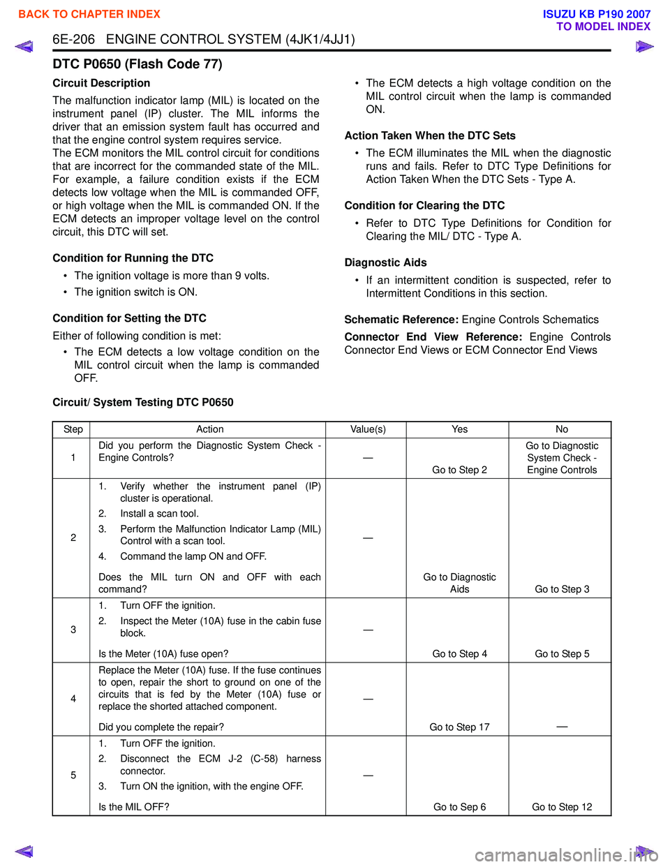
Circuit/ System Testing DTC P0650
Step Action Value(s)Yes No
1 Did you perform the Diagnostic System Check -
Engine Controls? —
Go to Step 2 Go to Diagnostic
System Check -
Engine Controls
2 1. Verify whether the instrument panel (IP)
cluster is operational.
2. Install a scan tool.
3. Perform the Malfunction Indicator Lamp (MIL) Control with a scan tool.
4. Command the lamp ON and OFF.
Does the MIL turn ON and OFF with each
command? —
Go to Diagnostic Aids Go to Step 3
3 1. Turn OFF the ignition.
2. Inspect the Meter (10A) fuse in the cabin fuse block.
Is the Meter (10A) fuse open? —
Go to Step 4 Go to Step 5
4 Replace the Meter (10A) fuse. If the fuse continues
to open, repair the short to ground on one of the
circuits that is fed by the Meter (10A) fuse or
replace the shorted attached component.
Did you complete the repair? —
Go to Step 17
—
51. Turn OFF the ignition.
2. Disconnect the ECM J-2 (C-58) harness connector.
3. Turn ON the ignition, with the engine OFF.
Is the MIL OFF? —
Go to Sep 6 Go to Step 12
BACK TO CHAPTER INDEX
TO MODEL INDEX
ISUZU KB P190 2007
Page 1940 of 6020
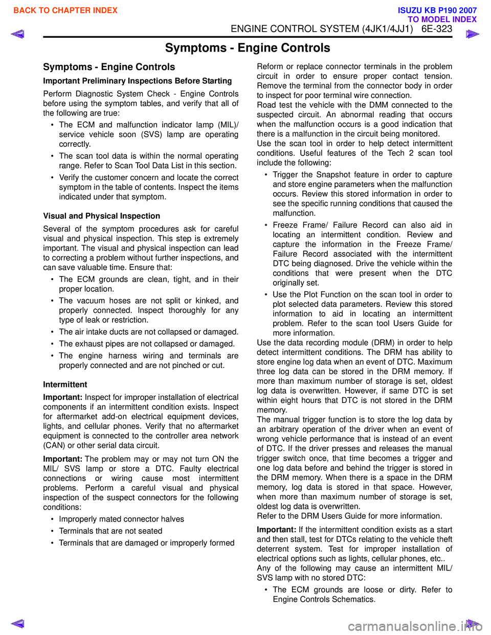
ENGINE CONTROL SYSTEM (4JK1/4JJ1) 6E-323
Symptoms - Engine Controls
Symptoms - Engine Controls
Important Preliminary Inspections Before Starting
Perform Diagnostic System Check - Engine Controls
before using the symptom tables, and verify that all of
the following are true:
• The ECM and malfunction indicator lamp (MIL)/ service vehicle soon (SVS) lamp are operating
correctly.
• The scan tool data is within the normal operating range. Refer to Scan Tool Data List in this section.
• Verify the customer concern and locate the correct symptom in the table of contents. Inspect the items
indicated under that symptom.
Visual and Physical Inspection
Several of the symptom procedures ask for careful
visual and physical inspection. This step is extremely
important. The visual and physical inspection can lead
to correcting a problem without further inspections, and
can save valuable time. Ensure that:
• The ECM grounds are clean, tight, and in their proper location.
• The vacuum hoses are not split or kinked, and properly connected. Inspect thoroughly for any
type of leak or restriction.
• The air intake ducts are not collapsed or damaged.
• The exhaust pipes are not collapsed or damaged.
• The engine harness wiring and terminals are properly connected and are not pinched or cut.
Intermittent
Important: Inspect for improper installation of electrical
components if an intermittent condition exists. Inspect
for aftermarket add-on electrical equipment devices,
lights, and cellular phones. Verify that no aftermarket
equipment is connected to the controller area network
(CAN) or other serial data circuit.
Important: The problem may or may not turn ON the
MIL/ SVS lamp or store a DTC. Faulty electrical
connections or wiring cause most intermittent
problems. Perform a careful visual and physical
inspection of the suspect connectors for the following
conditions:
• Improperly mated connector halves
• Terminals that are not seated
• Terminals that are damaged or improperly formed Reform or replace connector terminals in the problem
circuit in order to ensure proper contact tension.
Remove the terminal from the connector body in order
to inspect for poor terminal wire connection.
Road test the vehicle with the DMM connected to the
suspected circuit. An abnormal reading that occurs
when the malfunction occurs is a good indication that
there is a malfunction in the circuit being monitored.
Use the scan tool in order to help detect intermittent
conditions. Useful features of the Tech 2 scan tool
include the following:
• Trigger the Snapshot feature in order to capture and store engine parameters when the malfunction
occurs. Review this stored information in order to
see the specific running conditions that caused the
malfunction.
• Freeze Frame/ Failure Record can also aid in locating an intermittent condition. Review and
capture the information in the Freeze Frame/
Failure Record associated with the intermittent
DTC being diagnosed. Drive the vehicle within the
conditions that were present when the DTC
originally set.
• Use the Plot Function on the scan tool in order to plot selected data parameters. Review this stored
information to aid in locating an intermittent
problem. Refer to the scan tool Users Guide for
more information.
Use the data recording module (DRM) in order to help
detect intermittent conditions. The DRM has ability to
store engine log data when an event of DTC. Maximum
three log data can be stored in the DRM memory. If
more than maximum number of storage is set, oldest
log data is overwritten. However, if same DTC is set
within eight hours that DTC is not stored in the DRM
memory.
The manual trigger function is to store the log data by
an arbitrary operation of the driver when an event of
wrong vehicle performance that is instead of an event
of DTC. If the driver presses and releases the manual
trigger switch once, that time becomes a trigger and
one log data before and behind the trigger is stored in
the DRM memory. When there is a space in the DRM
memory, log data is stored in that space. However,
when more than maximum number of storage is set,
oldest log data is overwritten.
Refer to the DRM Users Guide for more information.
Important: If the intermittent condition exists as a start
and then stall, test for DTCs relating to the vehicle theft
deterrent system. Test for improper installation of
electrical options such as lights, cellular phones, etc..
Any of the following may cause an intermittent MIL/
SVS lamp with no stored DTC:
• The ECM grounds are loose or dirty. Refer to Engine Controls Schematics.
BACK TO CHAPTER INDEX
TO MODEL INDEX
ISUZU KB P190 2007
Page 1945 of 6020
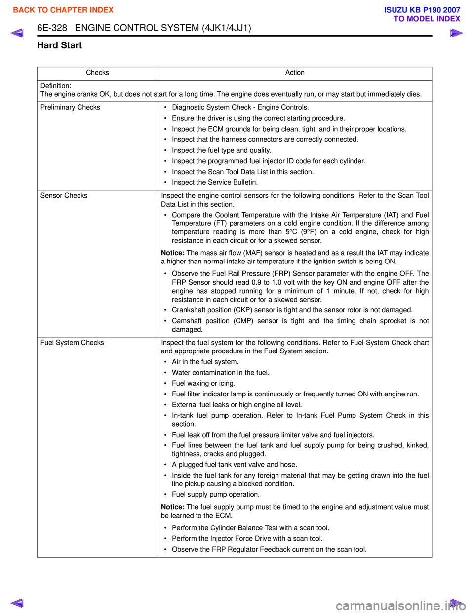
6E-328 ENGINE CONTROL SYSTEM (4JK1/4JJ1)
Hard Start
ChecksAction
Definition:
The engine cranks OK, but does not start for a long time. The engine does eventually run, or may start but immediately dies.
Preliminary Checks • Diagnostic System Check - Engine Controls.
• Ensure the driver is using the correct starting procedure.
• Inspect the ECM grounds for being clean, tight, and in their proper locations.
• Inspect that the harness connectors are correctly connected.
• Inspect the fuel type and quality.
• Inspect the programmed fuel injector ID code for each cylinder.
• Inspect the Scan Tool Data List in this section.
• Inspect the Service Bulletin.
Sensor Checks Inspect the engine control sensors for the following conditions. Refer to the Scan Tool
Data List in this section.
• Compare the Coolant Temperature with the Intake Air Temperature (IAT) and Fuel Temperature (FT) parameters on a cold engine condition. If the difference among
temperature reading is more than 5 °C (9 °F) on a cold engine, check for high
resistance in each circuit or for a skewed sensor.
Notice: The mass air flow (MAF) sensor is heated and as a result the IAT may indicate
a higher than normal intake air temperature if the ignition switch is being ON.
• Observe the Fuel Rail Pressure (FRP) Sensor parameter with the engine OFF. The FRP Sensor should read 0.9 to 1.0 volt with the key ON and engine OFF after the
engine has stopped running for a minimum of 1 minute. If not, check for high
resistance in each circuit or for a skewed sensor.
• Crankshaft position (CKP) sensor is tight and the sensor rotor is not damaged.
• Camshaft position (CMP) sensor is tight and the timing chain sprocket is not damaged.
Fuel System Checks Inspect the fuel system for the following conditions. Refer to Fuel System Check chart
and appropriate procedure in the Fuel System section.
• Air in the fuel system.
• Water contamination in the fuel.
• Fuel waxing or icing.
• Fuel filter indicator lamp is continuously or frequently turned ON with engine run.
• External fuel leaks or high engine oil level.
• In-tank fuel pump operation. Refer to In-tank Fuel Pump System Check in this section.
• Fuel leak off from the fuel pressure limiter valve and fuel injectors.
• Fuel lines between the fuel tank and fuel supply pump for being crushed, kinked, tightness, cracks and plugged.
• A plugged fuel tank vent valve and hose.
• Inside the fuel tank for any foreign material that may be getting drawn into the fuel line pickup causing a blocked condition.
• Fuel supply pump operation.
Notice: The fuel supply pump must be timed to the engine and adjustment value must
be learned to the ECM.
• Perform the Cylinder Balance Test with a scan tool.
• Perform the Injector Force Drive with a scan tool.
• Observe the FRP Regulator Feedback current on the scan tool.
BACK TO CHAPTER INDEX
TO MODEL INDEX
ISUZU KB P190 2007
Page 1947 of 6020
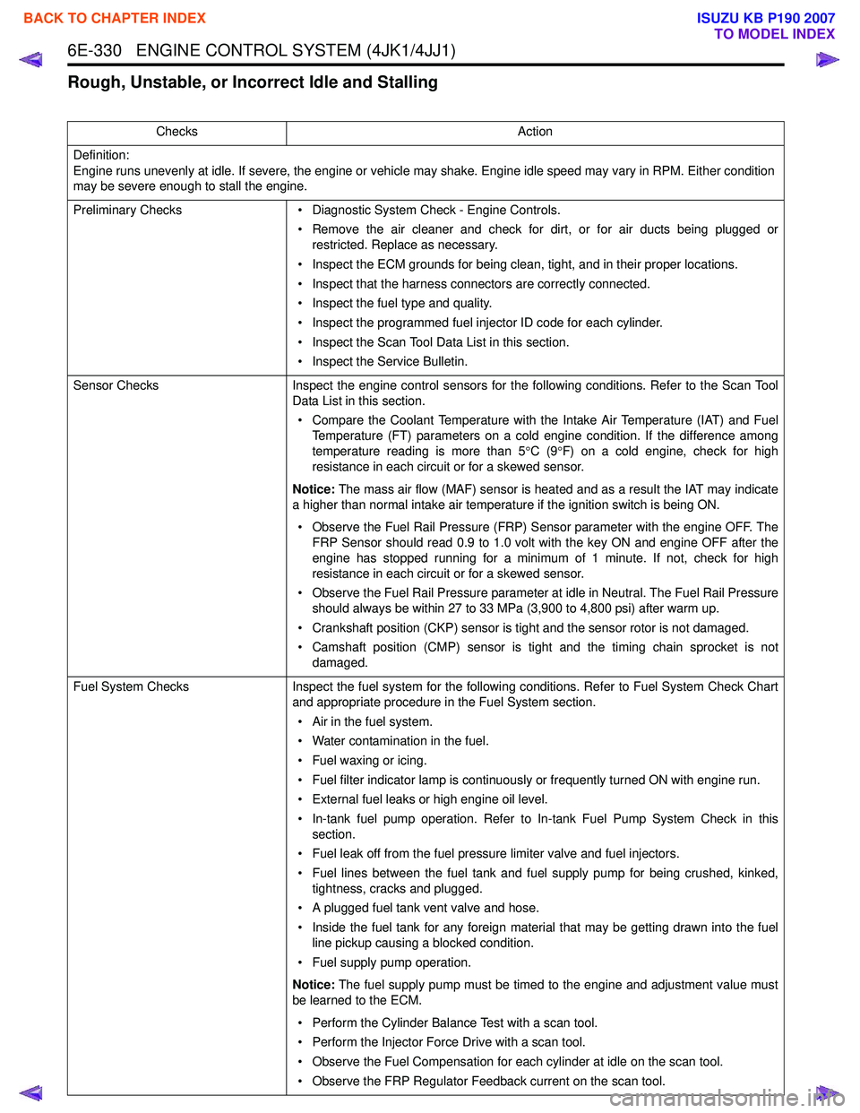
6E-330 ENGINE CONTROL SYSTEM (4JK1/4JJ1)
Rough, Unstable, or Incorrect Idle and Stalling
ChecksAction
Definition:
Engine runs unevenly at idle. If severe, the engine or vehicle may shake. Engine idle speed may vary in RPM. Either condition
may be severe enough to stall the engine.
Preliminary Checks • Diagnostic System Check - Engine Controls.
• Remove the air cleaner and check for dirt, or for air ducts being plugged or restricted. Replace as necessary.
• Inspect the ECM grounds for being clean, tight, and in their proper locations.
• Inspect that the harness connectors are correctly connected.
• Inspect the fuel type and quality.
• Inspect the programmed fuel injector ID code for each cylinder.
• Inspect the Scan Tool Data List in this section.
• Inspect the Service Bulletin.
Sensor Checks Inspect the engine control sensors for the following conditions. Refer to the Scan Tool
Data List in this section.
• Compare the Coolant Temperature with the Intake Air Temperature (IAT) and Fuel Temperature (FT) parameters on a cold engine condition. If the difference among
temperature reading is more than 5 °C (9 °F) on a cold engine, check for high
resistance in each circuit or for a skewed sensor.
Notice: The mass air flow (MAF) sensor is heated and as a result the IAT may indicate
a higher than normal intake air temperature if the ignition switch is being ON.
• Observe the Fuel Rail Pressure (FRP) Sensor parameter with the engine OFF. The FRP Sensor should read 0.9 to 1.0 volt with the key ON and engine OFF after the
engine has stopped running for a minimum of 1 minute. If not, check for high
resistance in each circuit or for a skewed sensor.
• Observe the Fuel Rail Pressure parameter at idle in Neutral. The Fuel Rail Pressure should always be within 27 to 33 MPa (3,900 to 4,800 psi) after warm up.
• Crankshaft position (CKP) sensor is tight and the sensor rotor is not damaged.
• Camshaft position (CMP) sensor is tight and the timing chain sprocket is not damaged.
Fuel System Checks Inspect the fuel system for the following conditions. Refer to Fuel System Check Chart
and appropriate procedure in the Fuel System section.
• Air in the fuel system.
• Water contamination in the fuel.
• Fuel waxing or icing.
• Fuel filter indicator lamp is continuously or frequently turned ON with engine run.
• External fuel leaks or high engine oil level.
• In-tank fuel pump operation. Refer to In-tank Fuel Pump System Check in this section.
• Fuel leak off from the fuel pressure limiter valve and fuel injectors.
• Fuel lines between the fuel tank and fuel supply pump for being crushed, kinked, tightness, cracks and plugged.
• A plugged fuel tank vent valve and hose.
• Inside the fuel tank for any foreign material that may be getting drawn into the fuel line pickup causing a blocked condition.
• Fuel supply pump operation.
Notice: The fuel supply pump must be timed to the engine and adjustment value must
be learned to the ECM.
• Perform the Cylinder Balance Test with a scan tool.
• Perform the Injector Force Drive with a scan tool.
• Observe the Fuel Compensation for each cylinder at idle on the scan tool.
• Observe the FRP Regulator Feedback current on the scan tool.
BACK TO CHAPTER INDEX
TO MODEL INDEX
ISUZU KB P190 2007