2007 ISUZU KB P190 phone
[x] Cancel search: phonePage 3301 of 6020
Engine Management – V6 – Diagnostics Page 6C1-2–23
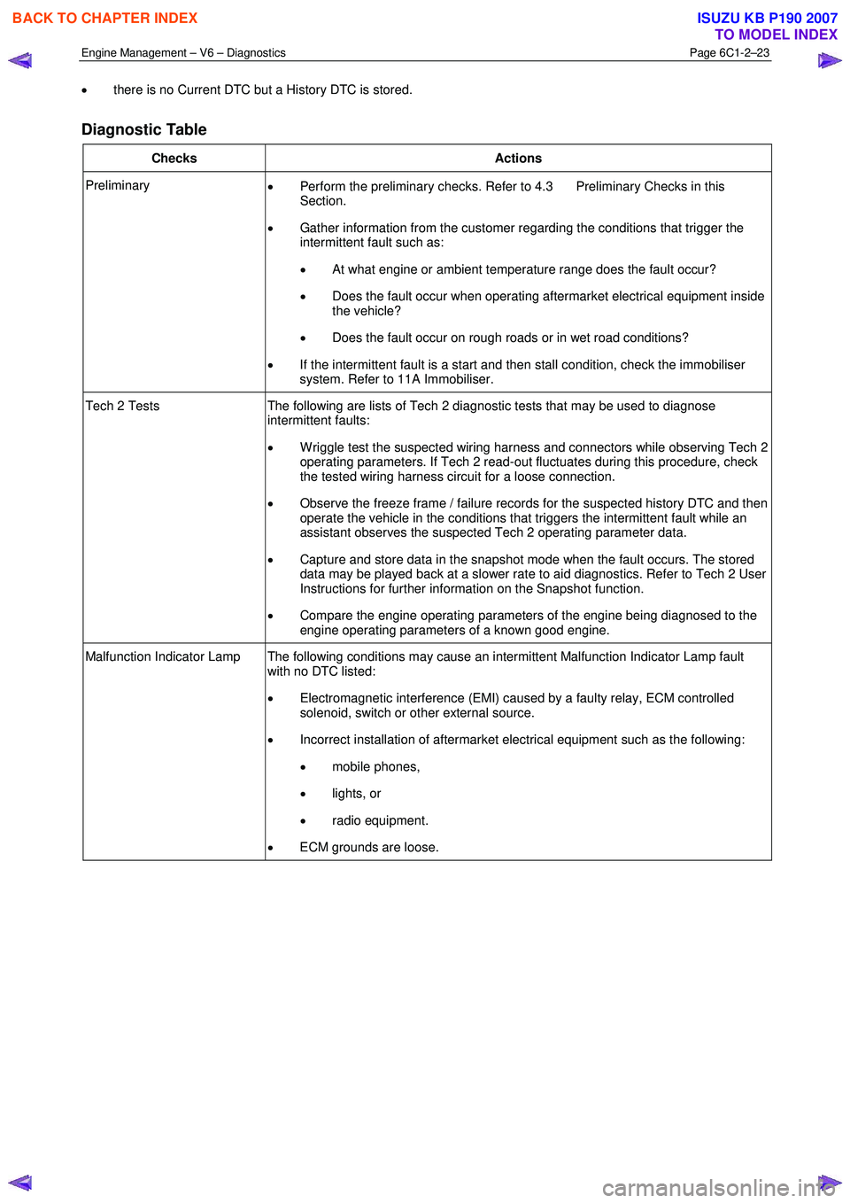
• there is no Current DTC but a History DTC is stored.
Diagnostic Table
Checks Actions
Preliminary
• Perform the preliminary checks. Refer to 4.3 Preliminary Checks in this
Section.
• Gather information from the customer regarding the conditions that trigger the
intermittent fault such as:
• At what engine or ambient temperature range does the fault occur?
• Does the fault occur when operating aftermarket electrical equipment inside
the vehicle?
• Does the fault occur on rough roads or in wet road conditions?
• If the intermittent fault is a start and then stall condition, check the immobiliser
system. Refer to 11A Immobiliser.
Tech 2 Tests The following are lists of Tech 2 diagnostic tests that may be used to diagnose
intermittent faults:
• W riggle test the suspected wiring harness and connectors while observing Tech 2
operating parameters. If Tech 2 read-out fluctuates during this procedure, check
the tested wiring harness circuit for a loose connection.
• Observe the freeze frame / failure records for the suspected history DTC and then
operate the vehicle in the conditions that triggers the intermittent fault while an
assistant observes the suspected Tech 2 operating parameter data.
• Capture and store data in the snapshot mode when the fault occurs. The stored
data may be played back at a slower rate to aid diagnostics. Refer to Tech 2 User
Instructions for further information on the Snapshot function.
• Compare the engine operating parameters of the engine being diagnosed to the
engine operating parameters of a known good engine.
Malfunction Indicator Lamp The following conditions may cause an intermittent Malfunction Indicator Lamp fault with no DTC listed:
• Electromagnetic interference (EMI) caused by a faulty relay, ECM controlled
solenoid, switch or other external source.
• Incorrect installation of aftermarket electrical equipment such as the following:
• mobile phones,
• lights, or
• radio equipment.
• ECM grounds are loose.
BACK TO CHAPTER INDEX
TO MODEL INDEX
ISUZU KB P190 2007
Page 3302 of 6020
Engine Management – V6 – Diagnostics Page 6C1-2–24
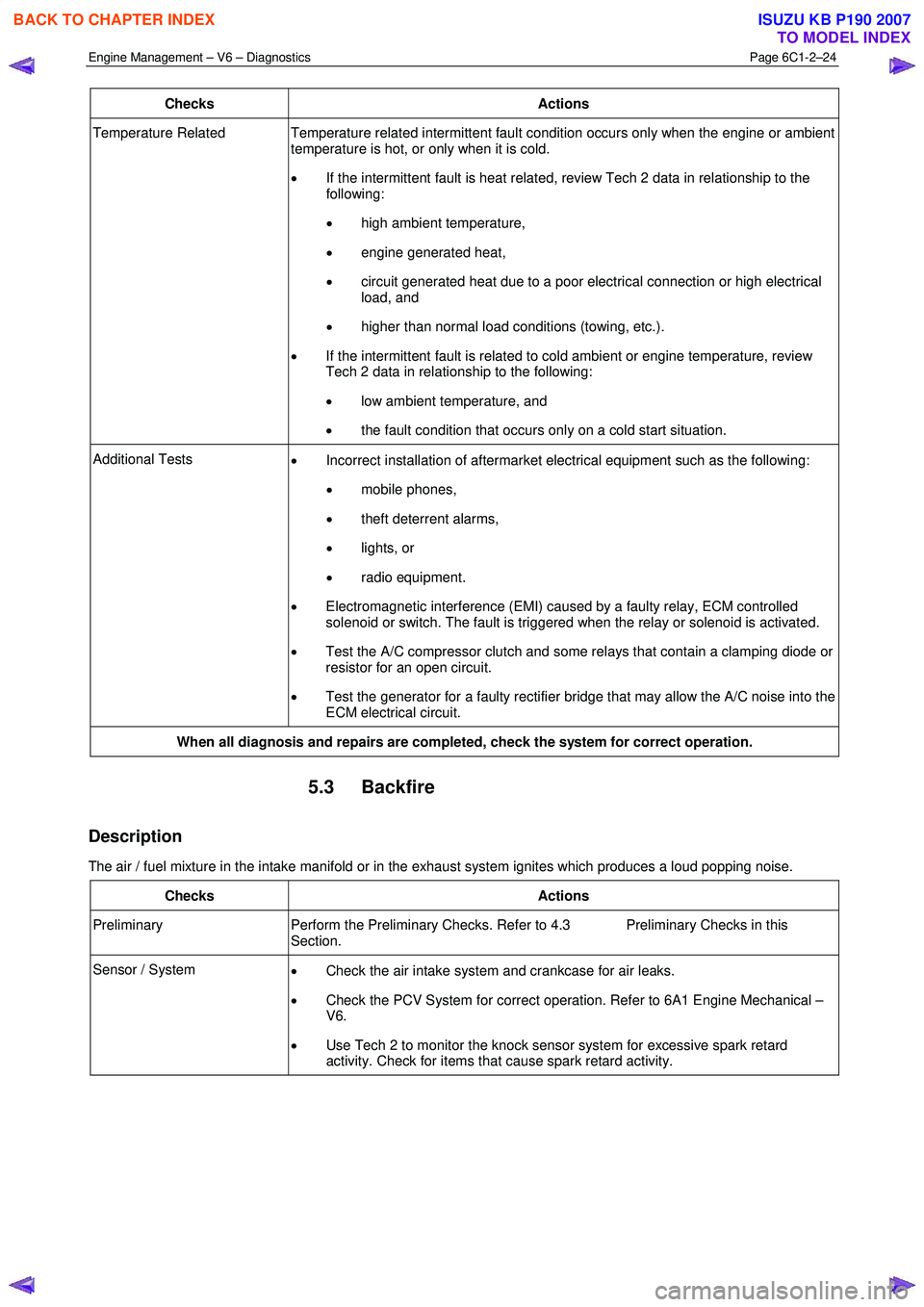
Checks Actions
Temperature Related Temperature related intermittent fault condition occurs only when the engine or ambient
temperature is hot, or only when it is cold.
• If the intermittent fault is heat related, review Tech 2 data in relationship to the
following:
• high ambient temperature,
• engine generated heat,
• circuit generated heat due to a poor electrical connection or high electrical
load, and
• higher than normal load conditions (towing, etc.).
• If the intermittent fault is related to cold ambient or engine temperature, review
Tech 2 data in relationship to the following:
• low ambient temperature, and
• the fault condition that occurs only on a cold start situation.
Additional Tests
• Incorrect installation of aftermarket electrical equipment such as the following:
• mobile phones,
• theft deterrent alarms,
• lights, or
• radio equipment.
• Electromagnetic interference (EMI) caused by a faulty relay, ECM controlled
solenoid or switch. The fault is triggered when the relay or solenoid is activated.
• Test the A/C compressor clutch and some relays that contain a clamping diode or
resistor for an open circuit.
• Test the generator for a faulty rectifier bridge that may allow the A/C noise into the
ECM electrical circuit.
When all diagnosis and repairs are completed, check the system for correct operation.
5.3 Backfire
Description
The air / fuel mixture in the intake manifold or in the exhaust system ignites which produces a loud popping noise.
Checks Actions
Preliminary Perform the Preliminary Checks. Refer to 4.3 Preliminary Checks in this
Section.
Sensor / System • Check the air intake system and crankcase for air leaks.
• Check the PCV System for correct operation. Refer to 6A1 Engine Mechanical –
V6.
• Use Tech 2 to monitor the knock sensor system for excessive spark retard
activity. Check for items that cause spark retard activity.
BACK TO CHAPTER INDEX
TO MODEL INDEX
ISUZU KB P190 2007
Page 3686 of 6020
Powertrain Interface Module – V6 Page 6E1–25
• Thorough inspection of the wiring circuits and connectors listed in the diagnostic procedures must be performed,
otherwise misdiagnosis may occur.
• Inspect the electrical circuitry or connector terminals that are suspected to be causing the complaint for the
following conditions:
• backed-out connector terminals,
• improper wiring connector mating,
• broken wiring connector locks,
• damaged connector terminals, and
• physical damage to the wiring harness.
• Before replacing a component, inspect its connector terminal for corrosion or deformation that may cause the fault
condition.
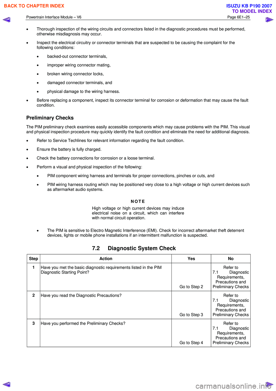
Preliminary Checks
The PIM preliminary check examines easily accessible components which may cause problems with the PIM. This visual
and physical inspection procedure may quickly identify the fault condition and eliminate the need for additional diagnosis.
• Refer to Service Techlines for relevant information regarding the fault condition.
• Ensure the battery is fully charged.
• Check the battery connections for corrosion or a loose terminal.
• Perform a visual and physical inspection of the following:
• PIM component wiring harness and terminals for proper connections, pinches or cuts, and
• PIM wiring harness routing which may be positioned very close to a high voltage or high current devices such
as aftermarket audio systems.
NOTE
High voltage or high current devices may induce
electrical noise on a circuit, which can interfere
with normal circuit operation.
• The PIM is sensitive to Electro Magnetic Interference (EMI). Check for incorrect aftermarket theft deterrent
devices, lights or mobile phone installations if an intermittent malfunction is suspected.
7.2 Diagnostic System Check
Step Action Yes No
1
Have you met the basic diagnostic requirements listed in the PIM
Diagnostic Starting Point?
Go to Step 2 Refer to
7.1 Diagnostic
Requirements,
Precautions and
Preliminary Checks
2 Have you read the Diagnostic Precautions?
Go to Step 3 Refer to
7.1 Diagnostic Requirements,
Precautions and
Preliminary Checks
3 Have you performed the Preliminary Checks?
Go to Step 4 Refer to
7.1 Diagnostic Requirements,
Precautions and
Preliminary Checks
BACK TO CHAPTER INDEX
TO MODEL INDEX
ISUZU KB P190 2007
Page 3690 of 6020
Powertrain Interface Module – V6 Page 6E1–29
Intermittent Fault Conditions
8.1 Intermittent Conditions Diagnostic Table
Description
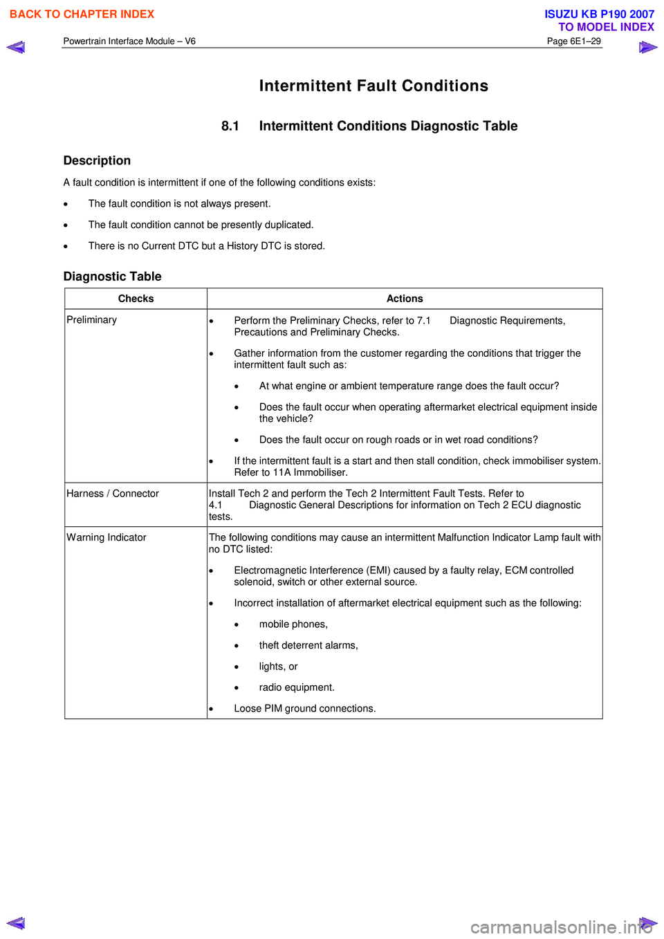
A fault condition is intermittent if one of the following conditions exists:
• The fault condition is not always present.
• The fault condition cannot be presently duplicated.
• There is no Current DTC but a History DTC is stored.
Diagnostic Table
Checks Actions
Preliminary
• Perform the Preliminary Checks, refer to 7.1 Diagnostic Requirements,
Precautions and Preliminary Checks.
• Gather information from the customer regarding the conditions that trigger the
intermittent fault such as:
• At what engine or ambient temperature range does the fault occur?
• Does the fault occur when operating aftermarket electrical equipment inside
the vehicle?
• Does the fault occur on rough roads or in wet road conditions?
• If the intermittent fault is a start and then stall condition, check immobiliser system.
Refer to 11A Immobiliser.
Harness / Connector Install Tech 2 and perform the Tech 2 Intermittent Fault Tests. Refer to 4.1 Diagnostic General Descriptions for information on Tech 2 ECU diagnostic
tests.
W arning Indicator The following conditions may cause an intermittent Malfunction Indicator Lamp fault with
no DTC listed:
• Electromagnetic Interference (EMI) caused by a faulty relay, ECM controlled
solenoid, switch or other external source.
• Incorrect installation of aftermarket electrical equipment such as the following:
• mobile phones,
• theft deterrent alarms,
• lights, or
• radio equipment.
• Loose PIM ground connections.
BACK TO CHAPTER INDEX
TO MODEL INDEX
ISUZU KB P190 2007
Page 3691 of 6020
Powertrain Interface Module – V6 Page 6E1–30
Checks Actions
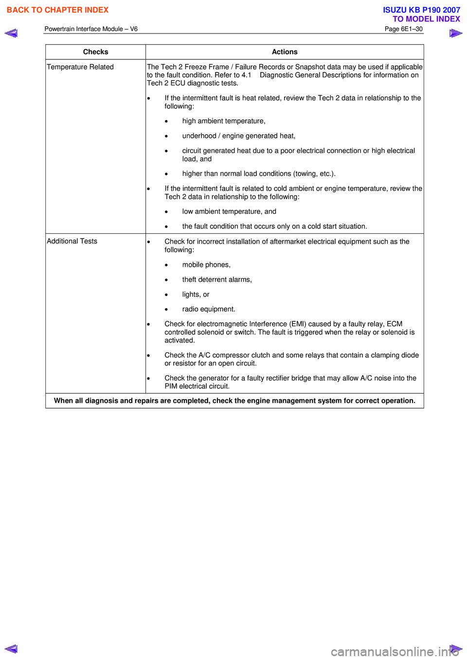
Temperature Related The Tech 2 Freeze Frame / Failure Records or Snapshot data may be used if applicable
to the fault condition. Refer to 4.1 Diagnostic General Descriptions for information on
Tech 2 ECU diagnostic tests.
• If the intermittent fault is heat related, review the Tech 2 data in relationship to the
following:
• high ambient temperature,
• underhood / engine generated heat,
• circuit generated heat due to a poor electrical connection or high electrical
load, and
• higher than normal load conditions (towing, etc.).
• If the intermittent fault is related to cold ambient or engine temperature, review the
Tech 2 data in relationship to the following:
• low ambient temperature, and
• the fault condition that occurs only on a cold start situation.
Additional Tests
• Check for incorrect installation of aftermarket electrical equipment such as the
following:
• mobile phones,
• theft deterrent alarms,
• lights, or
• radio equipment.
• Check for electromagnetic Interference (EMI) caused by a faulty relay, ECM
controlled solenoid or switch. The fault is triggered when the relay or solenoid is
activated.
• Check the A/C compressor clutch and some relays that contain a clamping diode
or resistor for an open circuit.
• Check the generator for a faulty rectifier bridge that may allow A/C noise into the
PIM electrical circuit.
When all diagnosis and repairs are completed, check the engine management system for correct operation.
BACK TO CHAPTER INDEX
TO MODEL INDEX
ISUZU KB P190 2007
Page 3780 of 6020
Automatic Transmission – 4L60E – General Information Page 7C1–20
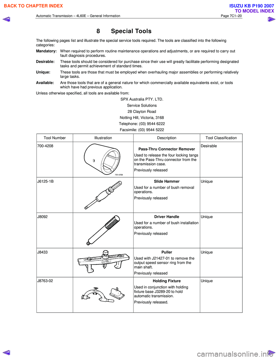
8 Special Tools
The following pages list and illustrate the special service tools required. The tools are classified into the following
categories:
Mandatory:
W hen required to perform routine maintenance operations and adjustments, or are required to carry out
fault diagnosis procedures.
Desirable:
These tools should be considered for purchase since their use will greatly facilitate performing designated
tasks and permit achievement of standard times.
Unique: These tools are those that must be employed when overhauling major assemblies or performing relatively
large tasks.
Available: Are those tools that are of a general nature for which commercially available equivalents exist, or tools
which have had previous application.
Unless otherwise specified, all tools are available from:
SPX Australia PTY. LTD. Service Solutions 28 Clayton Road
Notting Hill, Victoria, 3168
Telephone: (03) 9544 6222
Facsimile: (03) 9544 5222
Tool Number Illustration Description Tool Classification
700-4208
Pass-Thru Connector Remover
Used to release the four locking tangs
on the Pass-Thru connector from the
transmission case.
Previously released Desirable
J6125-1B
Slide Hammer
Used for a number of bush removal
operations.
Previously released Unique
J8092
Driver Handle
Used for a number of bush installation
operations.
Previously released Unique
J8433 Puller
Used with J21427-01 to remove the
output speed sensor ring from the
main shaft.
Previously released Unique
J8763-02 Holding Fixture
Used in conjunction with holding
fixture base J3289-20 to hold
automatic transmission.
Previously released. Unique
BACK TO CHAPTER INDEX
TO MODEL INDEX
ISUZU KB P190 2007
Page 3814 of 6020
Automatic Transmission – 4L60E – Electrical Diagnosis Page 7C2–28
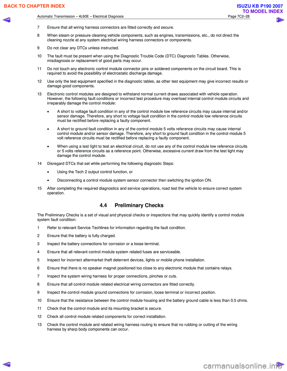
7 Ensure that all wiring harness connectors are fitted correctly and secure.
8 W hen steam or pressure cleaning vehicle components, such as engines, transmissions, etc., do not direct the cleaning nozzle at any system electrical wiring harness connectors or components.
9 Do not clear any DTCs unless instructed.
10 The fault must be present when using the Diagnostic Trouble Code (DTC) Diagnostic Tables. Otherwise, misdiagnosis or replacement of good parts may occur.
11 Do not touch any electronic control module connector pins or soldered components on the circuit board. This is required to avoid the possibility of electrostatic discharge damage.
12 Use only the test equipment specified in the diagnostic tables, as other test equipment may give incorrect results or damage good components.
13 Electronic control modules are designed to withstand normal current draws associated with vehicle operation. However, the following fault conditions or incorrect test procedure may overload internal control module circuits and
irreparably damage the control module:
• A short to voltage fault condition in any of the control module low reference circuits may cause internal and/or
sensor damage. Therefore, any short to voltage fault condition in the control module low reference circuits
must be rectified before replacing a faulty component.
• A short to ground fault condition in any of the control module 5 volts reference circuits may cause internal
control module and/or sensor damage. Therefore, any short to ground fault condition in the control module 5
volt reference circuits must be rectified before replacing a faulty component.
• W hen using a test light to test an electrical circuit, do not use any of the control module low reference circuits
or 5 volts reference circuits as a reference point. Otherwise, excessive current draw from the test light may
damage the control module.
14 Disregard DTCs that set while performing the following diagnostic Steps:
• Using the Tech 2 output control function, or
• Disconnecting a control module system sensor connector then switching the ignition ON.
15 After completing the required diagnostics and service operations, road test the vehicle to ensure correct system operation.
4.4 Preliminary Checks
The Preliminary Checks is a set of visual and physical checks or inspections that may quickly identify a control module
system fault condition:
1 Refer to relevant Service Techlines for information regarding the fault condition.
2 Ensure that the battery is fully charged.
3 Inspect the battery connections for corrosion or a loose terminal.
4 Ensure that all relevant control module system related fuses are serviceable.
5 Inspect for incorrect aftermarket theft deterrent devices, lights or mobile phone installation.
6 Ensure that there is no speaker magnet positioned too close to any electronic module that contains relays.
7 Inspect the system wiring harness for proper connections, pinches or cuts.
8 Ensure that all control module related electrical wiring connectors are fitted correctly.
9 Inspect the control module ground connections for corrosion, loose terminal or incorrect position.
10 Ensure that the resistance between the control module housing and the battery ground cable is less than 0.5 ohms.
11 Check that the control module and its mounting bracket is secure.
12 Check all control module related components for correct installation.
13 Check the control module and related wiring harness routing to ensure that no rubbing or cutting of the wiring harness by sharp body components can occur.
BACK TO CHAPTER INDEX
TO MODEL INDEX
ISUZU KB P190 2007
Page 4376 of 6020
7A2-92 TRANSMISSION CONTROL SYSTEM (JR405E)
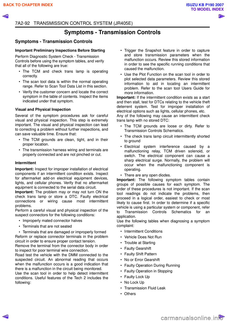
Symptoms - Transmission Controls
Symptoms - Transmission Controls
Important Preliminary Inspections Before Starting
Perform Diagnostic System Check - Transmission
Controls before using the symptom tables, and verify
that all of the following are true:
• The TCM and check trans lamp is operating correctly.
• The scan tool data is within the normal operating range. Refer to Scan Tool Data List in this section.
• Verify the customer concern and locate the correct symptom in the table of contents. Inspect the items
indicated under that symptom.
Visual and Physical Inspection
Several of the symptom procedures ask for careful
visual and physical inspection. This step is extremely
important. The visual and physical inspection can lead
to correcting a problem without further inspections, and
can save valuable time. Ensure that:
• The TCM grounds are clean, tight, and in their proper location.
• The transmission harness wiring and terminals are properly connected and are not pinched or cut.
Intermittent
Important: Inspect for improper installation of electrical
components if an intermittent condition exists. Inspect
for aftermarket add-on electrical equipment devices,
lights, and cellular phones. Verify that no aftermarket
equipment is connected to the serial data circuit.
Important: The problem may or may not turn ON the
check trans lamp or store a DTC. Faulty electrical
connections or wiring cause most intermittent
problems.
Perform a careful visual and physical inspection of the
suspect connectors for the following conditions:
• Improperly mated connector halves
• Terminals that are not seated
• Terminals that are damaged or improperly formed
Reform or replace connector terminals in the problem
circuit in order to ensure proper contact tension.
Remove the terminal from the connector body in order
to inspect for poor terminal wire connection.
Road test the vehicle with the DMM connected to the
suspected circuit. An abnormal reading that occurs
when the malfunction occurs is a good indication that
there is a malfunction in the circuit being monitored.
Use the scan tool in order to help detect intermittent
conditions. Useful features of the Tech 2 includes the
following: • Trigger the Snapshot feature in order to capture
and store transmission parameters when the
malfunction occurs. Review this stored information
in order to see the specific running conditions that
caused the malfunction.
• Use the Plot Function on the scan tool in order to plot selected data parameters. Review this stored
information to aid in locating an intermittent
problem. Refer to the scan tool Users Guide for
more information.
Important: If the intermittent condition exists as a start
and then stall, test for DTCs relating to the vehicle theft
deterrent system. Test for improper installation of
electrical options such as lights, cellular phones, etc.
Any of the following may cause an intermittent check
trans lamp with no stored DTC:
• The TCM grounds are loose or dirty. Refer to Transmission Controls Schematics.
• The check trans lamp circuit intermittently shorted to ground
• Electrical system interference caused by a malfunctioning relay, TCM driven solenoid, or
switch. The electrical component can cause a
sharp electrical surge. Normally, the problem will
occur when the malfunctioning component is
operating.
• There are any open diodes.
Important: The following symptom tables contain
groups of possible causes for each symptom. The
order of these procedures is not important. If the scan
tool readings do not indicate the problems, then
proceed in a logical order, easiest to check or most
likely to cause first. In order to determine if a specific
vehicle is using a particular system or component, refer
to Transmission Controls Schematics for an
application.
Use the following tables when diagnosing a symptom
complaint:
• Intermittent Conditions
• Vehicle Does Not Run
• Trouble at Starting
• Faulty Gearshift
• Faulty Shift Pattern
• No or Error Gearshift
• Faulty Operation During Running
• Faulty Operation in Stopping
• Faulty Lock Up
• No Lock Up
• Transmission Fluid Leak
•Others
BACK TO CHAPTER INDEX
TO MODEL INDEX
ISUZU KB P190 2007