2007 ISUZU KB P190 phone
[x] Cancel search: phonePage 2402 of 6020
6E–232 ENGINE DRIVEABILITY AND EMISSIONS
SYMPTOM DIAGNOSIS
PRELIMINARY CHECKS
Before using this section, perform the “On-Board
Diagnostic (OBD) System Check” and verify all of the
following items:
• The engine control module (ECM) and malfunction indicator lamp (MIL = Check Engine Lamp) are
operating correctly.
• There are no Diagnostic Trouble Code(s) stored.
• Tech 2 data is within normal operating range. Refer to Typical Scan Data Values.
• Verify the customer complaint and locate the correct symptom in the table of contents. Perform the
procedure included in the symptom chart.
VISUAL/PHYSICAL CHECK
Several of the symptom procedures call for a careful
visual/physical check. This can lead to correcting a
problem without further checks and can save valuable
time. This check should include the following items:
• ECM grounds for cleanliness, tightness and proper location.
• Vacuum hoses for splits, kinks, and proper connection, shown on the “Emission Control System
Schematics”. Check thoroughly for any type of leak or
restriction.
• Air intake ducts for collapsed or damaged areas.
• Air leaks at throttle body mounting area, manifold absolute pressure (MAP) sensor and intake manifold
sealing surfaces.
• Ignition wires for cracking, harness, and carbon tracking.
• Wiring for proper connections, pinches and cuts.
INTERMITTENT
Important: An intermittent problem may or may not turn
on the malfunction indicator lamp (MIL) or store a
Diagnostic Trouble Code. Do NOT use the Diagnostic
Trouble Code (DTC) charts for intermittent problems.
The fault must be present to locate the problem.
Most intermittent problems are cased by faulty electrical
connections or wiring. Perform a careful visual/physical
check for the following conditions.
• Poor mating of the connector halves or a terminal not fully seated in the connector (backed out).
• Improperly formed or damaged terminal.
• All connector terminals in the problem circuit should be carefully checked for proper contact tension.
• Poor terminal-to-wire connection. This requires removing the terminal form the connector body to
check.
• Ignition coils shorted to ground and arcing at ignition wires or plugs. • MIL (Check Engine Lamp) wire to ECM shorted to
ground.
• Poor ECM grounds. Refer to the ECM wiring diagrams.
Road test the vehicle with a Digital Multimeter
connected to a suspected circuit. An abnormal voltage
when the malfunction occurs is a good indication that
there is a fault in the circuit being monitored.
Using Tech 2 to help detect intermittent conditions. The
Tech 2 has several features that can be used to located
an intermittent condition.
An intermittent MIL (Check Engine Lamp) with no stored
Diagnostic Trouble Code may be caused by the
following:
• Ignition coil shorted to ground and arcing at ignition wires or plugs.
• MIL (Check Engine Lamp) wire to ECM short to ground.
• Poor ECM grounds. Refer to the ECM wiring diagrams.
Check for improper installation of electrical options such
as light, cellular phones, etc. Check all wires from ECM
to the ignition control module for poor connections.
Check for an open diode across the A/C compressor
clutch and check for other open diodes (refer to wiring
diagrams in Electrical Diagnosis).
If problem has not been found, refer to ECM connector
symptom tables.
• Check the “Broadcast Code” of the ECM, and compare it with the latest Isuzu service bulletins and/
or Isuzu EEPROM reprogramming equipment to
determine if an update to the ECM’s reprogrammable
memory has been released.
To check the “Broadcast Code”, connect the Tech 2,
then look for “ID info.” then select “Broadcast Code”.
This should display a 4 character code, such as “XBYA”
(example only).
This identifies the contents of the reprogrammable
software and calibration contained in the ECM.
If the “Broadcast Code” is not the most current
available, it is advisable to reprogram the ECM’s
EEPROM memory, which may either help identify a
hard-to find problem or may fix the problem.
The Service Programming System (SPS) will not allow
incorrect software programming or incorrect calibration
changes.
BACK TO CHAPTER INDEX
TO MODEL INDEX
ISUZU KB P190 2007
Page 3221 of 6020
Fuel System – V6 Page 6C – 19
Remove
• A depressurised fuel system contains fuel
in the fuel filter and fuel lines that can be
spilled during service operations.
• Fuel vapour remains in the fuel tank even
when completely empty. Seal all openings
in the fuel tank using suitable material or a
plastic plug. Ensure no naked flames or
other ignition sources are nearby. Ensure
all cellular phones (and transmission
devices that may cause any metal objects
to become unintentional receiving
antennas) are switched off.
• Place a dry chemical (Class B) fire
extinguisher nearby before performing any
on-vehicle service procedures. Failure to
follow these precautions may result in
personal injury.
1 Remove the fuel pump relay, refer to 8A Electrical Body and Chassis.
2 Depressurise the fuel system, refer to 3.4 Fuel System Depressurisation.
Never drain or store fuel into an open
container, due to the possibility of fire or
explosion.
3 Siphon the fuel tank, using commercially-available equipment.
Before proceeding, clean all traces of dirt and
other foreign material from the top of the fuel
tank, near the modular fuel pump and sender
assembly.
7 Place a drain tray under the fuel filter area.
Fuel can spill from the disconnected filter.
BACK TO CHAPTER INDEX
TO MODEL INDEX
ISUZU KB P190 2007
Page 3225 of 6020
Fuel System – V6 Page 6C – 23
4.5 Modular Fuel Pump and Sender
Assembly
NOTE
If the modular fuel pump and sender assembly
develops a fault it must be replaced as a
complete unit. The only serviced parts are the
retainer locking ring and the O-ring seal.
Remove
• A depressurised fuel system contains fuel
in the fuel filter and fuel lines that can be
spilled during service operations.
• Fuel vapour remains in the fuel tank even
when completely empty. Seal all openings
in the fuel tank using suitable material or a
plastic plug. Ensure no naked flames or
other ignition sources are nearby. Ensure
all cellular phones (and transmission
devices that may cause any metal objects
to become unintentional receiving
antennas) are switched off.
• Place a dry chemical (Class B) fire
extinguisher nearby before performing any
on-vehicle service procedures. Failure to
follow these precautions may result in
personal injury.
• Wear safety glasses when using
compressed air. Do not blow compressed
air directly onto any body part.
1 Remove the fuel pump relay, refer to 8A Engine Body and Chassis.
2 Remove the fuel tank assembly from the vehicle, refer to 4.4 Fuel Tank.
Before proceeding, clean all traces of dirt and
other foreign material from the top of the fuel
tank, near the modular fuel pump and sender
assembly.
3 Use compressed air to ensure all dirt and foreign materials are removed from all fuel connections before disconnecting the parts.
Fuel can spill from the disconnected modular
fuel pump and sender assembly.
BACK TO CHAPTER INDEX
TO MODEL INDEX
ISUZU KB P190 2007
Page 3228 of 6020
Fuel System – V6 Page 6C – 26
Fuel vapour remains in the fuel tank even
when completely empty. Seal all openings in
the fuel tank using suitable material or a
plastic plug. Ensure no naked flames or other
ignition sources are nearby. Ensure all
cellular phones (and transmission devices
that may cause any metal objects to become
unintentional receiving antennas) are
switched off.
15 Place a suitable material over the opening in the fuel tank to prevent any foreign matter from entering the fuel system.
Fuel Level Sender Assembly
Test
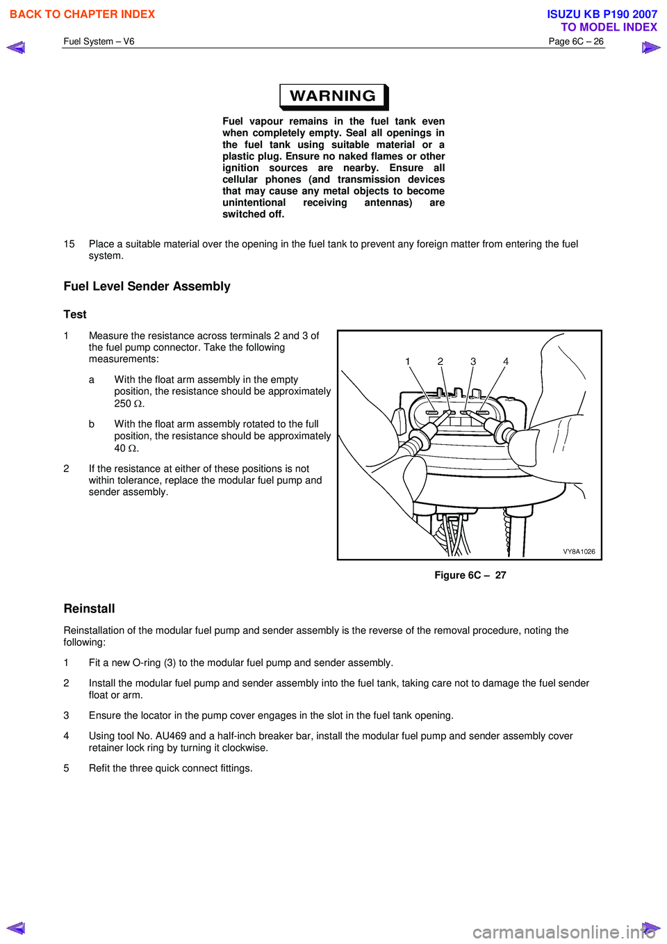
1 Measure the resistance across terminals 2 and 3 of the fuel pump connector. Take the following
measurements:
a W ith the float arm assembly in the empty position, the resistance should be approximately
250 Ω.
b W ith the float arm assembly rotated to the full position, the resistance should be approximately
40 Ω.
2 If the resistance at either of these positions is not within tolerance, replace the modular fuel pump and
sender assembly.
Figure 6C – 27
Reinstall
Reinstallation of the modular fuel pump and sender assembly is the reverse of the removal procedure, noting the
following:
1 Fit a new O-ring (3) to the modular fuel pump and sender assembly.
2 Install the modular fuel pump and sender assembly into the fuel tank, taking care not to damage the fuel sender float or arm.
3 Ensure the locator in the pump cover engages in the slot in the fuel tank opening.
4 Using tool No. AU469 and a half-inch breaker bar, install the modular fuel pump and sender assembly cover retainer lock ring by turning it clockwise.
5 Refit the three quick connect fittings.
BACK TO CHAPTER INDEX
TO MODEL INDEX
ISUZU KB P190 2007
Page 3232 of 6020
Fuel System – V6 Page 6C – 30
4.7 Fuel Tank Siphon Procedure
• Fuel vapour remains in the modular fuel
pump and sender assembly and fuel lines
that can be spilled during service
operations. Ensure no naked flames or
other ignition sources are nearby. Ensure
all cellular phones (and transmission
devices that may cause any metal objects
to become unintentional receiving
antennas) are switched off.
• Place a dry chemical (Class B) fire
extinguisher nearby before performing any
on-vehicle service procedures. Failure to
follow these precautions may result in
personal injury.
For an exploded view of fuel tank components, refer Figure 6C – 17.
1 Depressurise the fuel system, refer to 3.4 Fuel System Depressurisation.
2 Reinstall the fuel pump relay, refer to 8A Electrical Body and Chassis.
Disconnecting the battery affects certain
vehicle electronic systems. 1.1 WARNING,
CAUTION and NOTES.
3 Disconnect the negative battery terminal.
4 Remove the fuel filler cap.
NOTE
Lubricate the fuel siphon hose with J36850
TransJel Transmission Assembly Lubricant or
equivalent to aid hose insertion. Use only an
approved lubricant.
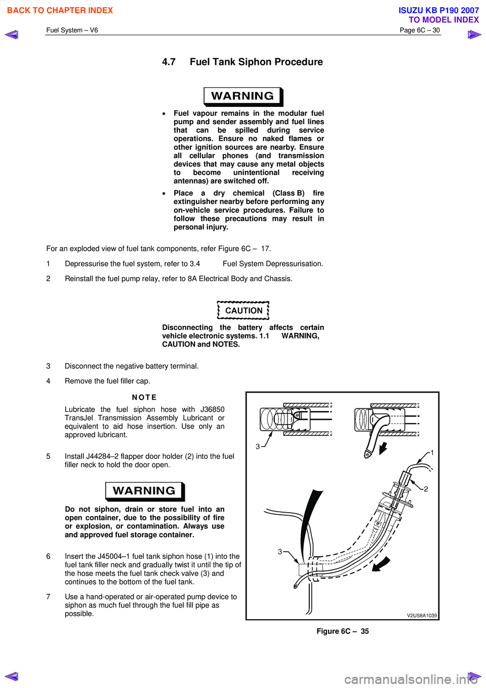
5 Install J44284–2 flapper door holder (2) into the fuel filler neck to hold the door open.
Do not siphon, drain or store fuel into an
open container, due to the possibility of fire
or explosion, or contamination. Always use
and approved fuel storage container.
6 Insert the J45004–1 fuel tank siphon hose (1) into the fuel tank filler neck and gradually twist it until the tip of
the hose meets the fuel tank check valve (3) and
continues to the bottom of the fuel tank.
7 Use a hand-operated or air-operated pump device to siphon as much fuel through the fuel fill pipe as
possible.
Figure 6C – 35
BACK TO CHAPTER INDEX
TO MODEL INDEX
ISUZU KB P190 2007
Page 3233 of 6020
Fuel System – V6 Page 6C – 31
Fuel vapour remains in the fuel tank even
when completely empty. Seal all openings in
the fuel tank using suitable material or a
plastic plug. Ensure no naked flames or other
ignition sources are nearby. Ensure all
cellular phones (and transmission devices
that may cause any metal objects to become
unintentional receiving antennas) are
switched off.
Do not use excessive force when removing
the fuel siphon hose from the fuel filler neck.
If the fuel siphon hose gets stuck upon
removal, gently twist and tug the fuel siphon
hose back and forth until it releases.
NOTE
• If fuel does not siphon from the fuel tank, the
fuel siphon hose may have entered the fuel
tank through a roof-facing check valve
opening. If required, insert the J45004–1 fuel
siphon hose (1) into the fuel tank filler neck,
refer to Figure 6C – 35, but twist the fuel
siphon hose 90° as it slides down the filler
neck. This enables the fuel siphon hose to
enter the fuel tank through a floor-facing
check valve opening.
• The siphon procedure will not remove all fuel
from the fuel tank. If required, fuel remaining
in the fuel tank may be siphoned out through
the top of the fuel tank, once the modular fuel
pump and sender assembly is removed from
the tank, refer to 4.4 Fuel Tank.
8 Remove the siphon equipment.
BACK TO CHAPTER INDEX
TO MODEL INDEX
ISUZU KB P190 2007
Page 3235 of 6020
Fuel System – V6 Page 6C – 33
4.9 Fuel Lines
Remove
• A depressurised fuel system contains fuel
in the fuel filter and fuel lines that can be
spilled during service operations.
• Fuel vapour remains in the fuel tank even
when completely empty. Seal all openings
in the fuel tank using suitable material or a
plastic plug. Ensure no naked flames or
other ignition sources are nearby. Ensure
all cellular phones (and transmission
devices that may cause any metal objects
to become unintentional receiving
antennas) are switched off.
• Place a dry chemical (Class B) fire
extinguisher nearby before performing any
on-vehicle service procedures. Failure to
follow these precautions may result in
personal injury.
• Wear safety glasses when using
compressed air. Do not blow compressed
air onto any body part.
1 Remove the fuel pump relay, refer to 8A Electrical Body and Chassis.
2 Depressurise the fuel system, refer to 3.4 Fuel System Depressurisation.
Never drain or store fuel into an open
container, due to the possibility of fire or
explosion.
3 Raise the vehicle, preferably on a hoist, refer to 0A General Information.
Before proceeding, clean all traces of dirt and
other foreign material from the fuel lines.
4 Use compressed air to ensure that all dirt and foreign materials are removed from all fuel connections before the parts are disconnected.
5 If required, remove the stone guard, refer to Figure 6C – 17 and fuel lines. Use the following illustrations showing the fuel line layout and location of other items relating to the fuel system as a guide, also refer to 4.1 Fuel Lines
And Quick Connect Fittings and 4.6 Evaporative Emission Control Canister.
BACK TO CHAPTER INDEX
TO MODEL INDEX
ISUZU KB P190 2007
Page 3297 of 6020
Engine Management – V6 – Diagnostics Page 6C1-2–19
• Do not start the engine if the battery terminal is not properly secured to the battery.
• Do not disconnect or reconnect the following while the ignition is switched on or when the engine is running:
− Any engine management system component electrical wiring connector, or
− Battery terminal leads.
• Ensure the correct procedure for disconnecting and connecting engine management system electrical wiring
connectors is always followed. For information on the correct procedure for disconnecting and connecting specific
wiring connectors, refer to 6C1-3 Engine Management – V6 – Service Operations.
• Ensure that all wiring harness connectors are fitted correctly.
• W hen steam or pressure cleaning engines, do not direct the cleaning nozzle at engine management system
components.
• Do not clear any DTCs unless instructed.
• The fault must be present when using the diagnostic trouble code (DTC) diagnostic tables. Otherwise,
misdiagnosis or replacement of good parts may occur.
• Do not touch the ECM connector pins or soldered components on the ECM circuit board to prevent ECM
Electrostatic Discharge damage. Refer to 8A Electrical - Body and Chassis for information on Electrostatic
Discharge.
• Use only the test equipment specified in the diagnostic tables as other test equipment may give incorrect results or
damage good components.
• The ECM is designed to withstand normal current draw associated with vehicle operations. However, the following
fault conditions or incorrect test procedure may overload the ECM internal circuit and damage the ECM:
− A short to voltage fault condition in any of the ECM low reference circuits may cause internal ECM and / or
sensor damage. Therefore, any short to voltage fault condition in the ECM low reference circuits must be
rectified before replacing a faulty component.
− A short to ground fault condition in any of the ECM 5 V reference circuits may cause internal ECM and / or
sensor damage. Therefore, any short to ground fault condition in the ECM 5 V reference circuits must be
rectified before replacing a faulty component.
− W hen using a test lamp to test an electrical circuit, do not use any of the ECM low reference circuits or 5 V
reference circuits as a reference point. Otherwise, excessive current draw from the test lamp may damage
the ECM.
• Disregard DTCs that set while performing the following diagnostic Steps:
− Using Tech 2 actuator tests, or
− Disconnecting an engine management system sensor connector then switching on the ignition.
• After completing the required diagnostics and service operations, road test the vehicle to ensure correct engine
management system operation.
4.3 Preliminary Checks
The preliminary checks are a set of visual and physical checks or inspections that may quickly identify engine
management system fault condition.
• Refer to the appropriate Service Techlines for relevant information regarding the fault condition.
• Ensure the battery is fully charged.
• Inspect the battery connections for corrosion or a loose terminal.
• Ensure that all engine management system related fuses are serviceable.
• Inspect for incorrect aftermarket theft deterrent devices, lights or mobile phone installation.
• Ensure there is no speaker magnet positioned too close to any electronic module that contains relays.
• Inspect the engine wiring harness for proper connections, pinches or cuts.
• Ensure that all engine management related electrical wiring connectors are fitted correctly.
• Inspect the ECM ground connections for corrosion, loose terminal or incorrect position.
BACK TO CHAPTER INDEX
TO MODEL INDEX
ISUZU KB P190 2007