Page 3931 of 6020

Automatic Transmission – 4L60E – On-vehicle Servicing Page 7C4–18
Ensure the four wheels are off the ground
before performing the starting test.
4 W ith the ignition switched to the ON position, check if the engine can only be started in the Park and Neutral shift selector positions and ensure the back-up lamps illuminate when Reverse is selected. A further minor adjustment
may be required to achieve this state.
NOTE
To gain access to the rear attaching screw (11) it
will be necessary to remove the connector.
5 After the switch has been adjusted, tighten the rear attaching screw (11) to the correct torque specification. Neutral start and back-up lamp switch
attaching screw torque specification .................. 25.0 Nm
6 Reinstall the connector and the CPA securing pin.
7 Remove the switch front attaching screw (1).
8 Install the heat shield (3) and tighten the attaching screws (1 and 2) to the correct torque specification.
Heat shield front attaching screw
torque specification ............................................ 25.0 Nm
Heat shield rear attaching screw torque specification ..............................................9.0 Nm
9 Lower the vehicle to the ground and re-check the operation of the neutral start and back-up lamp switch. The vehicle must start only with the shift selector in the Park or Neutral positions and the back-up lamps should only
illuminate when Reverse is selected.
3.5 Vehicle Speed Sensor
NOTE
For the speed sensor fitted to four wheel drive
vehicles (4WD), refer to 7D Transfer Case and
Adaptor Housing.
Remove
1 Raise the vehicle and support in a safe manner, refer
to 0A General Information for the location of support
points.
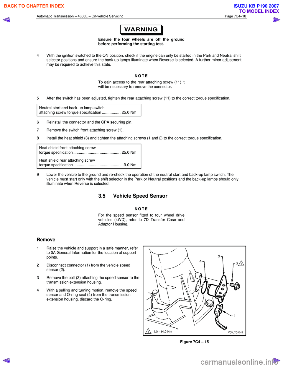
2 Disconnect connector (1) from the vehicle speed sensor (2).
3 Remove the bolt (3) attaching the speed sensor to the transmission extension housing.
4 With a pulling and turning motion, remove the speed sensor and O-ring seal (4) from the transmission
extension housing, discard the O-ring.
Figure 7C4 – 15
BACK TO CHAPTER INDEX
TO MODEL INDEX
ISUZU KB P190 2007
Page 3956 of 6020

Automatic Transmission – 4L60E – On-vehicle Servicing Page 7C4–43
If the verifier disc does not clip into place, the
quick-connect fitting is not engaged, rectify
as required.
10 As a security check, push and clip each verification disc into place over the quick-connect fittings. If difficulty is experienced, repeat the installation process until the verification disc can be clipped into place over the radiator
quick-connect fitting.
11 Snap the outlet cooler line (4) in the clip (5) of the radiator fan shroud.
12 Ensure the routeing of the cooler lines is correct and there is no fouling of the lines.
13 Tighten the screw attaching the cooler lines bracket to the correct torque specifications.
Transmission cooler lines bracket
attaching screw torque specification .................. 23.0 Nm
14 If required, top up the transmission fluid level (cold).
15 Start the engine and check for any fluid leak at the fittings. If a leak is found, stop the engine and rectify the leak.
16 Check and top up the transmission fluid to the correct level as required, refer to 2.1 Transmission Fluid.
3.18 Transmission Assembly
Remove
Disconnection of the battery affects certain
vehicle electronic systems. Refer to 6D1-3
Battery, before disconnecting the battery.
1 Disconnect the battery ground lead.
2 Raise the vehicle and support in a safe manner, refer to 0A General Information for the location of support points.
3 Remove the heat shield from the neutral start and back-up lamp switch, gently prise the selector cable from the transmission external manual shaft linkage and remove the selector cable from the bracket, refer to
3.3 Selector Cable Assembly.
4 Disconnect the harness connectors from the following:
a Vehicle speed sensor, refer to 3.5 Vehicle Speed Sensor.
b Neutral start and back-up switch, refer to 3.4 Neutral Start and Back-up Lamp Switch.
c For the following on four wheel drive vehicles (4W D), refer to 7D Transfer Case and Adaptor Housing:
• neutral switch,
• 2WD – 4WD shift actuator switch,
• speed sensor.
NOTE
If the battery is connected, avoid turning the
ignition switch to the ON position, as the transfer
case control module (TTCM) must first be
removed (memory to be cleared as Check 4W D
Indicator will light).
5 Remove the following components: a Front and centre exhaust assemblies, refer to 6F Exhaust System.
BACK TO CHAPTER INDEX
TO MODEL INDEX
ISUZU KB P190 2007
Page 4286 of 6020

7A2-2 TRANSMISSION CONTROL SYSTEM (JR405E)
Specifications
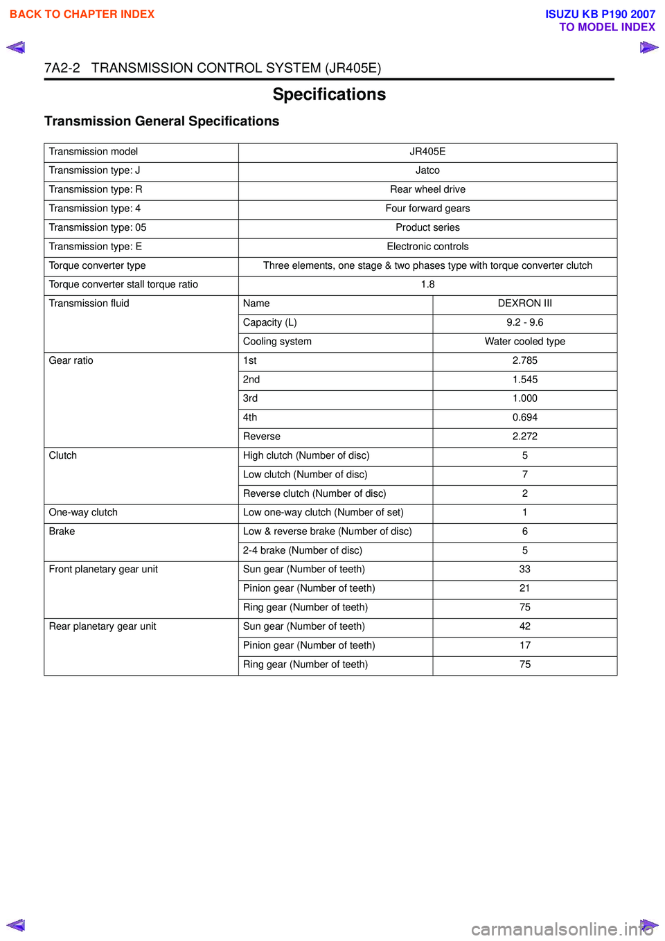
Transmission General Specifications
Transmission modelJR405E
Transmission type: J Jatco
Transmission type: R Rear wheel drive
Transmission type: 4 Four forward gears
Transmission type: 05 Product series
Transmission type: E Electronic controls
Torque converter type Three elements, one stage & two phases type with torque converter clutch
Torque converter stall torque ratio 1.8
Transmission fluid Name DEXRON III
Capacity (L) 9.2 - 9.6
Cooling system Water cooled type
Gear ratio 1st 2.785
2nd 1.545
3rd 1.000
4th 0.694
Reverse 2.272
Clutch High clutch (Number of disc) 5
Low clutch (Number of disc) 7
Reverse clutch (Number of disc) 2
One-way clutch Low one-way clutch (Number of set) 1
Brake Low & reverse brake (Number of disc) 6
2-4 brake (Number of disc) 5
Front planetary gear unit Sun gear (Number of teeth) 33
Pinion gear (Number of teeth) 21
Ring gear (Number of teeth) 75
Rear planetary gear unit Sun gear (Number of teeth) 42
Pinion gear (Number of teeth) 17
Ring gear (Number of teeth) 75
BACK TO CHAPTER INDEX
TO MODEL INDEX
ISUZU KB P190 2007
Page 4877 of 6020
TRANSFER CONTROL SYSTEM 7D1-3
General Description
RTW 77DLF000501
Transfer Position and Drive Mode
Three drive modes can be selected through operation of 4W D switch.
Transfer Position 4WD SWITCH Mode Drive mode
2H RW D Rear wheel drive
HIGH
4H 4W D (HIGH) High-speed mechanical
lock-up four wheel drive
LOW 4L 4W D (LOW ) Low-speed mechanical
lock-up four wheel drive
NEUTRAL 2H & 4L (10 Sec) NEUTRAL Towed by other vehicle
BACK TO CHAPTER INDEX
TO MODEL INDEX
ISUZU KB P190 2007
Page 4950 of 6020

8A-12 ELECTRICAL-BODY AND CHASSIS
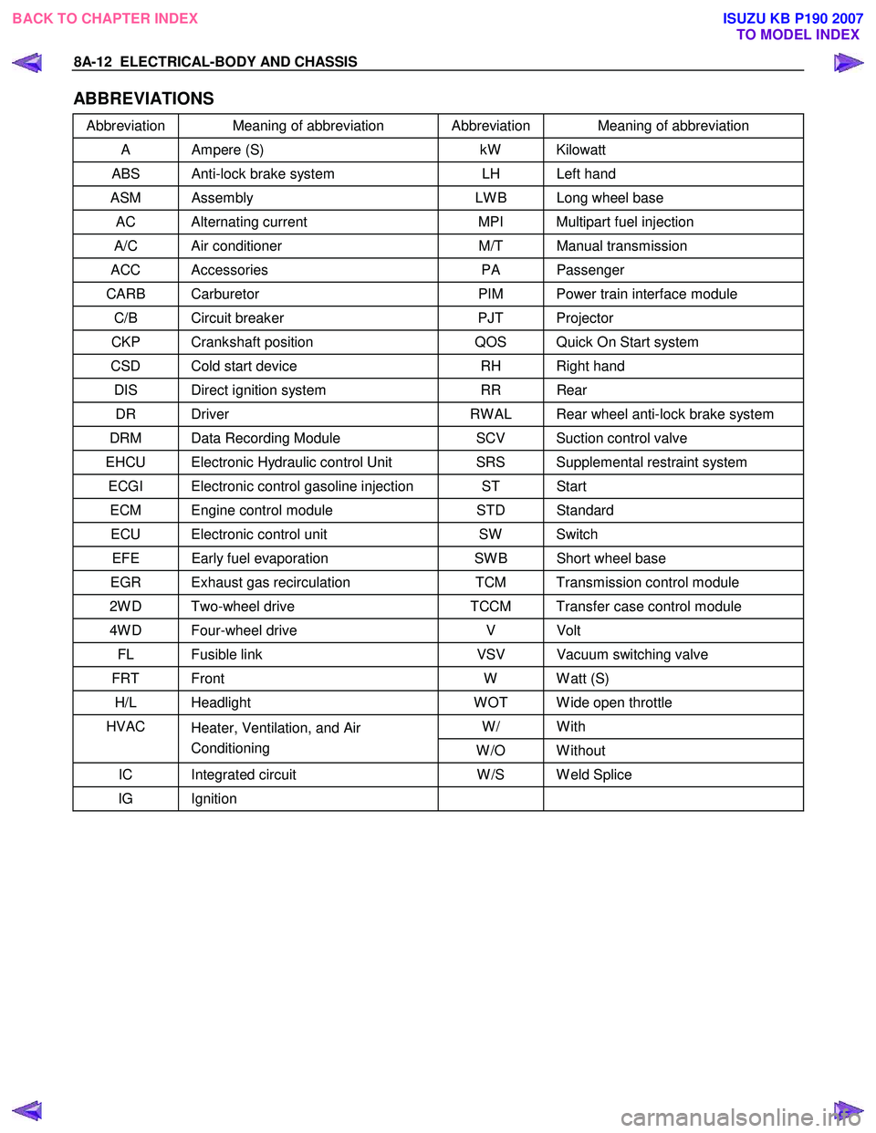
ABBREVIATIONS
Abbreviation Meaning of abbreviation Abbreviation Meaning of abbreviation
A Ampere (S) kW Kilowatt
ABS Anti-lock brake system LH Left hand
ASM Assembly LW B Long wheel base
AC Alternating current MPI Multipart fuel injection
A/C Air conditioner M/T Manual transmission
ACC Accessories PA Passenger
CARB Carburetor PIM Power train interface module
C/B Circuit breaker PJT Projector
CKP Crankshaft position QOS Quick On Start system
CSD Cold start device RH Right hand
DIS Direct ignition system RR Rear
DR Driver RW AL Rear wheel anti-lock brake system
DRM Data Recording Module SCV Suction control valve
EHCU Electronic Hydraulic control Unit SRS Supplemental restraint system
ECGI Electronic control gasoline injection ST Start
ECM Engine control module STD Standard
ECU Electronic control unit SW Switch
EFE Early fuel evaporation SW B Short wheel base
EGR Exhaust gas recirculation TCM Transmission control module
2W D Two-wheel drive TCCM Transfer case control module
4W D Four-wheel drive V Volt
FL Fusible link VSV Vacuum switching valve
FRT Front W W att (S)
H/L Headlight W OT W ide open throttle
W/ With HVAC
Heater, Ventilation, and Air
Conditioning W /O W ithout
IC Integrated circuit W /S W eld Splice
IG Ignition
BACK TO CHAPTER INDEX
TO MODEL INDEXISUZU KB P190 2007
Page 5180 of 6020
8A-242 ELECTRICAL-BODY AND CHASSIS
HORN SWITCH
Removal
1. Disable the SRS (Refer to “Disabling the SRS” in Section
9A).
2. Insertion hole for pin push bar at below the steering wheel indicated arrow.
RTW 78ASH001901
3. Check the position of the pins in the holes before insert the
pin push bar. Push the pin in the direction of the arrow.
4. Push the four pins using the φ5 ∼6 bar for cancel the lock on
the four pins.
RTW 78ASH002201
5. Disconnect the SRS air bag connector 1 and horn lead
connector
2 and remove the air bag assembly.
6. Remove the horn switch.
RTW 78ASH002401
Installation
1. Connect the SRS bag connector and horn lead connector.
2. Align each snap stud of the driver air bag to the hole in the steering wheel.
BACK TO CHAPTER INDEX TO MODEL INDEXISUZU KB P190 2007
Page:
< prev 1-8 9-16 17-24