2007 ISUZU KB P190 four wheel drive
[x] Cancel search: four wheel drivePage 2785 of 6020
Engine Mechanical – V6 Page 6A1–8
Page 6A1–8
1 General Information
The HFV6 engine features a closed vee, deep skirt die cast aluminium cylinder block with cast iron cylinder liners,
internally balanced crankcase, full length wa ter jackets and six bolt main bearing caps.
The cylinders are arranged in two banks of three with a 60 degree included angle between the two banks.
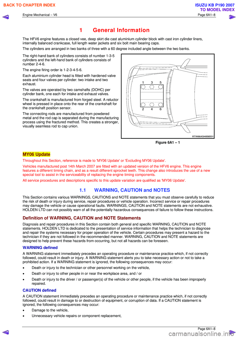
The right-hand bank of cylinders consists of number 1-3-5
cylinders and the left-hand bank of cylinders consists of
number 2-4-6.
The engine firing order is 1-2-3-4-5-6.
Each aluminium cylinder head is fitted with hardened valve
seats and four valves per cylinder: two intake and two
exhaust.
The valves are operated by two camshafts (DOHC) per
cylinder bank, one each for intake and exhaust valves.
The crankshaft is manufactured from forged steel. A reluctor
wheel is pressed in place onto the rear of the crankshaft for
the crankshaft position sensor.
The connecting rods are m anufactured from powdered
metal and the rod cap is separ ated during the manufacturing
process using the fractured me thod. This creates a stronger,
visually seamless rod to cap union.
Figure 6A1 – 1
MY06 Update
Throughout this Section, reference is made to 'MY06 Update' or 'Excluding MY06 Update'.
Vehicles manufactured post 14th Marc h 2007 are fitted with an updated version of the HFV6 engine. This engine
features a different timing chain, and as a result different sprocket teeth. This change also introduces the use of a new
special tool to assist in the serviceab ility of replacing the engine timing components.
All service procedures and descriptions specific to this update variation are qualified as 'MY06 Update'.
1.1 WARNING, CAUTION and NOTES
This Section contains various WARNING S, CAUTIONS and NOTE statements that y ou must observe carefully to reduce
the risk of death or injury during servic e, repair procedures or vehicle operation. Incorrect service or repair procedures
may damage the vehicle or cause operat ional faults. WARNINGS, CAUTION and NOTE statements are not exhaustive.
HOLDEN LTD can not possibly warn of a ll the potentially hazardous consequences of failure to follow these instructions.
Definition of WARNING, CAUTION and NOTE Statements
Diagnosis and repair procedures in this Section contain both general and specific WARNING, CAUTION and NOTE
statements. HOLDEN LTD is dedicated to the presentation of service information that helps the technician to diagnose
and repair the systems necessary for proper operation of the vehicle. Certain procedures may present a hazard to the
technician if they are not followed in the reco mmended manner. WARNING, CAUTION and NOTE statements are
designed to help prevent these hazards from o ccurring, but not all hazards can be foreseen.
WARNING defined
A WARNING statement immediately precedes an operating procedure or maint enance practice which, if not correctly
followed, could result in death or injury . A WARNING statement alerts you to ta ke necessary action or not to take a
prohibited action. If a WARNING statement is ignored, the following consequences may occur:
• Death or injury to the technician or other personnel working on the vehicle,
• Death or injury to other people in or near the workplace area, and / or
• Death or injury to the driver / or passenger(s) of the vehicle or other people, if the vehicle has been improperly
repaired.
CAUTION defined
A CAUTION statement immediately prec edes an operating procedure or maintenance practice which, if not correctly
followed, could result in damage to or destruction of equi pment, or corruption of data. If a CAUTION statement is
ignored, the following consequences may occur:
• Damage to the vehicle,
• Unnecessary vehicle repairs or component replacement,
BACK TO CHAPTER INDEX
TO MODEL INDEX
ISUZU KB P190 2007
Page 2800 of 6020
Engine Mechanical – V6 Page 6A1–23
Page 6A1–23
Crankshaft
The crankshaft is a forged steel design with four main bearings. The number three main bearing controls crankshaft
thrust. A crankshaft position reluctor wheel is pressed onto the rear of the crankshaft, in front of the rear main journal.
The crankshaft is internally balanced with an integral oil pum p drive machined into the nose in front of the front main
journal.
Pistons, Pins and Connecting Rods
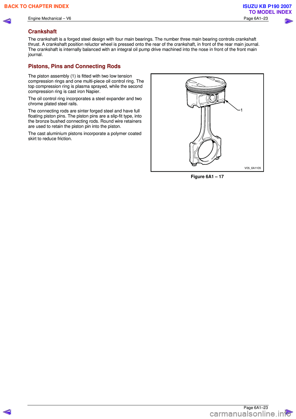
The piston assembly (1) is fitted with two low tension
compression rings and one multi-piece oil control ring. The
top compression ring is plasma sprayed, while the second
compression ring is cast iron Napier.
The oil control ring incorpor ates a steel expander and two
chrome plated steel rails.
The connecting rods are sint er forged steel and have full
floating piston pins. The piston pi ns are a slip-fit type, into
the bronze bushed connecting rods. Round wire retainers
are used to retain the piston pin into the piston.
The cast aluminium pistons incorporate a polymer coated
skirt to reduce friction.
Figure 6A1 – 17
BACK TO CHAPTER INDEX
TO MODEL INDEX
ISUZU KB P190 2007
Page 3020 of 6020
Engine Mechanical – V6 Page 6A1–243
Page 6A1–243
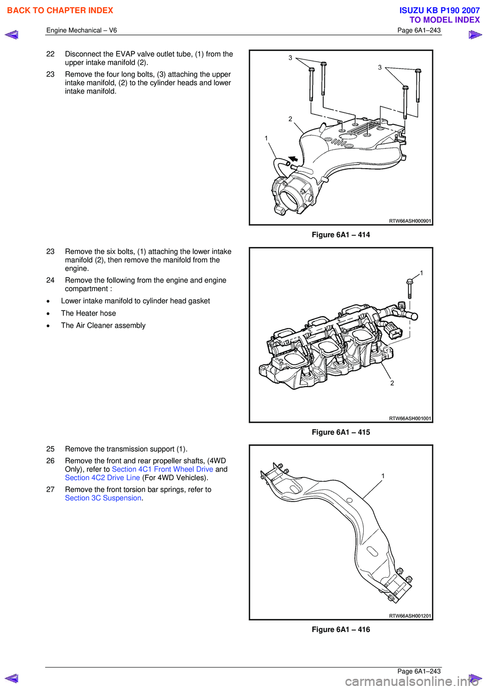
22 Disconnect the EVAP valve outlet tube, (1) from the
upper intake manifold (2).
23 Remove the four long bolts, (3) attaching the upper intake manifold, (2) to the cylinder heads and lower
intake manifold.
Figure 6A1 – 414
23 Remove the six bolts, (1) attaching the lower intake manifold (2), then remove the manifold from the
engine.
24 Remove the following from the engine and engine compartment :
• Lower intake manifold to cylinder head gasket
• The Heater hose
• The Air Cleaner assembly
Figure 6A1 – 415
25 Remove the transmission support (1).
26 Remove the front and rear propeller shafts, (4WD Only), refer to Section 4C1 Front Wheel Drive and
Section 4C2 Drive Line (For 4WD Vehicles).
27 Remove the front torsion bar springs, refer to Section 3C Suspension .
Figure 6A1 – 416
BACK TO CHAPTER INDEX
TO MODEL INDEX
ISUZU KB P190 2007
Page 3380 of 6020
Engine Management – V6 – Diagnostics Page 6C1-2–102
3-way catalytic converter damage. The malfunction indicator lamp (MIL) will flash ON and OFF when the conditions for
catalytic converter damage are present. DTCs P0301 through P0306 correspond to cylinders 1 through 6. If the ECM is
able to determine that a specific cylinder is misfiring, the DTC for that cylinder will set. If the misfire rate is sufficient to
cause emission levels to exceed a predetermined value, this DTC sets.
Conditions for Running the DTC
• DTCs P0121, P0122, P0123, P0221, P0222, P0223, P0335, P0336, or P0338 are not set.
• The engine speed is between 400 – 7,000 rpm and steady.
• The delivered torque signal is more than 10 percent at idle.
• The delivered torque signal is between 9 – 30 percent with the transmission in drive.
• The intake air temperature (IAT) is more than –30° C.
• The fuel level is more than 12 percent.
• The torque management is not active.
• DTC P0300 runs continuously when the above conditions exist for at least 1,000 engine revolutions.
Conditions for Setting the DTC
• The ECM detects a crankshaft rotation speed variation indicating a misfire rate sufficient to cause emissions levels
to exceed mandated standards.
• The condition above exists for more than 4 seconds.
Action Taken When the DTC Sets
• The control module activates the MIL on the second ignition cycle that the diagnostic runs and fails.
• The control module records the operating conditions at the time the diagnostic fails. The first time the diagnostic
fails, the control module stores this information in the Failure Records. If the diagnostic reports a failure on the
second consecutive ignition cycle, the control module records the operating conditions at the time of the failure.
The control module writes the operating conditions to the Freeze Frame and updates the Failure Records.
Conditions for Clearing the MIL/DTC
• The ECM turns OFF the malfunction indicator lamp (MIL) after four consecutive ignition cycles that the diagnostic
runs and does not fail.
• A current DTC, Last Test Failed, clears when the diagnostic runs and passes.
• A history DTC clears after 40 consecutive warm-up cycles, if no failures are reported by this or any other emission
related diagnostic.
• Use Tech 2 to clear the MIL and the DTC.
Additional Information
• A misfire DTC could be caused by an excessive vibration from sources other than the engine. Inspect for the
following possible sources:
− A tyre or wheel that is out of round or out of balance
− Variable thickness brake rotors
− An unbalanced drive shaft
− Certain rough road conditions
− A damaged accessory drive component or belt
• A misfire DTC could be caused by a camshaft actuator stuck in the full advance or retard position.
• For an intermittent condition, refer to 5.2 Intermittent Fault Conditions in this Section.
BACK TO CHAPTER INDEX
TO MODEL INDEX
ISUZU KB P190 2007
Page 3383 of 6020
Engine Management – V6 – Diagnostics Page 6C1-2–105
Circuit Description
The engine control module (ECM) uses information from the crankshaft position (CKP) sensor and the camshaft position
(CMP) sensor to determine when an engine misfire is occurring. By monitoring variations in the crankshaft rotation
speed for each cylinder, the ECM is able to detect individual misfire events. A misfire rate that is high enough can cause
3-way catalytic converter damage. The malfunction indicator lamp (MIL) will flash ON and OFF when the conditions for
catalytic converter damage are preset. DTCs P0301 – P0306 correspond to cylinders 1 to 6. If the ECM is able to
determine that a specific cylinder is misfiring, the DTC for that cylinder sets.
Conditions for Running the DTC
• DTCs P0121, P0122, P0123, P0221, P0222, P0223, P0335, P0336, or P0338 are not set.
• The engine speed is between 400 – 7,000 rpm and steady.
• The delivered torque signal is more than 10 percent at idle with the transmission in neutral.
• The delivered torque signal is between 10 – 30 percent with the transmission in drive.
• The intake air temperature (IAT) is more than –30° C.
• The engine run time is more than 45 seconds.
• The fuel level is more than 12 percent.
• The torque management is not active.
• DTCs P0301, P0302, P0303, P0304, P0305, and P0306 run continuously when the above conditions exist for at
least 1,000 engine revolutions.
Conditions for Setting the DTC
• The ECM detects a crankshaft rotation speed variation indicating a single cylinder misfire rate sufficient to cause
emissions levels to exceed mandated standards.
• The condition exists for more than 4 seconds.
Action Taken When the DTC Sets
• The control module activates the MIL on the second ignition cycle that the diagnostic runs and fails.
• The control module records the operating conditions at the time the diagnostic fails. The first time the diagnostic
fails, the control module stores this information in the Failure Records. If the diagnostic reports a failure on the
second consecutive ignition cycle, the control module records the operating conditions at the time of the failure.
The control module writes the operating conditions to the Freeze Frame and updates the Failure Records.
Conditions for Clearing the MIL/DTC
• The ECM turns OFF the malfunction indicator lamp (MIL) after four consecutive ignition cycles that the diagnostic
runs and does not fail.
• A current DTC, Last Test Failed, clears when the diagnostic runs and passes.
• A history DTC clears after 40 consecutive warm-up cycles, if no failures are reported by this or any other emission
related diagnostic.
• Use Tech 2 to clear the MIL and the DTC.
Additional Information
• A misfire DTC could be caused by an excessive vibration from sources other than the engine. Check for the
following possible sources:
− Tyre or wheel out of round or balance
− Variable thickness brake rotor or drum
− Drive shaft not balanced
− Certain rough road conditions
BACK TO CHAPTER INDEX
TO MODEL INDEX
ISUZU KB P190 2007
Page 3612 of 6020
Starting System – V6 Page 6D1-2–4
• Clarify a procedure,
• Present additional information for accomplishing a procedure,
• Give insight into the reasons for performing a procedure in the recommended manner, and / or
Present information that gives the technician the benefit of past experience in accomplishing a procedure with greater
ease.
1.2 Components
Starting System Components
The main components of the starting system are:
• battery,
• wiring,
• ignition switch,
• theft deterrent engine crank inhibitor (a function of the theft deterrent system),
• park / neutral and back-up switch (on vehicles with 4 speed automatic transmission),
• engine control module (ECM),
• start relay,
• solenoid switch, and
• starter motor.
Starter Motor and Solenoid Switch Components
Solenoid Switch
The solenoid switch is used to activate the DC motor and has two windings; the pull-in winding and the hold-in winding.
The pull-in winding has heavier wire and is grounded through the DC motor winding and brushes. The hold-in winding is
grounded through the solenoid casing.
Planetary Drive Train
The planetary drive train consists of an internally toothed ring gear and three planetary gear wheels, which rotate on
sleeve bearings on the planetary drive shaft. The ring gear is keyed into the drive-end housing and is made from
high-grade polyamide with mineral additives.
W hen the starter motor operates, the armature turns the planetary gears inside the fixed planetary ring gear. This drives
the planetary shaft at a reduced speed ratio which turns the drive assembly. A fork lever in the drive-end housing forces
the drive assembly forward to engage with the flexplate / flywheel ring gear on the engine and transmit cranking torque.
An internal clutch allows the drive assembly pinion gear to rotate freely when the engine starts. This prevents the
armature from being driven at excessive speed by the engine.
Armature
The armature shaft is supported at each end by oil absorbent, sintered metal bushes; one in the commutator end shield
and one in the planetary drive shaft. The front end of the armature has a gear profile. This meshes with the three
planetary gear wheels. These in turn, mesh with the internal teeth of the ring gear.
Brushes
A brush plate supports four commutator brushes. This plate is fixed to the commutator end shield with two retaining
screws. Two negative brushes are grounded to the pole housing. The two positive brushes are insulated from the pole
housing and connected to the solenoid switch M terminal, refer to Figure 6D1-2 – 1.
BACK TO CHAPTER INDEX
TO MODEL INDEX
ISUZU KB P190 2007
Page 3774 of 6020
Automatic Transmission – 4L60E – General Information Page 7C1–14
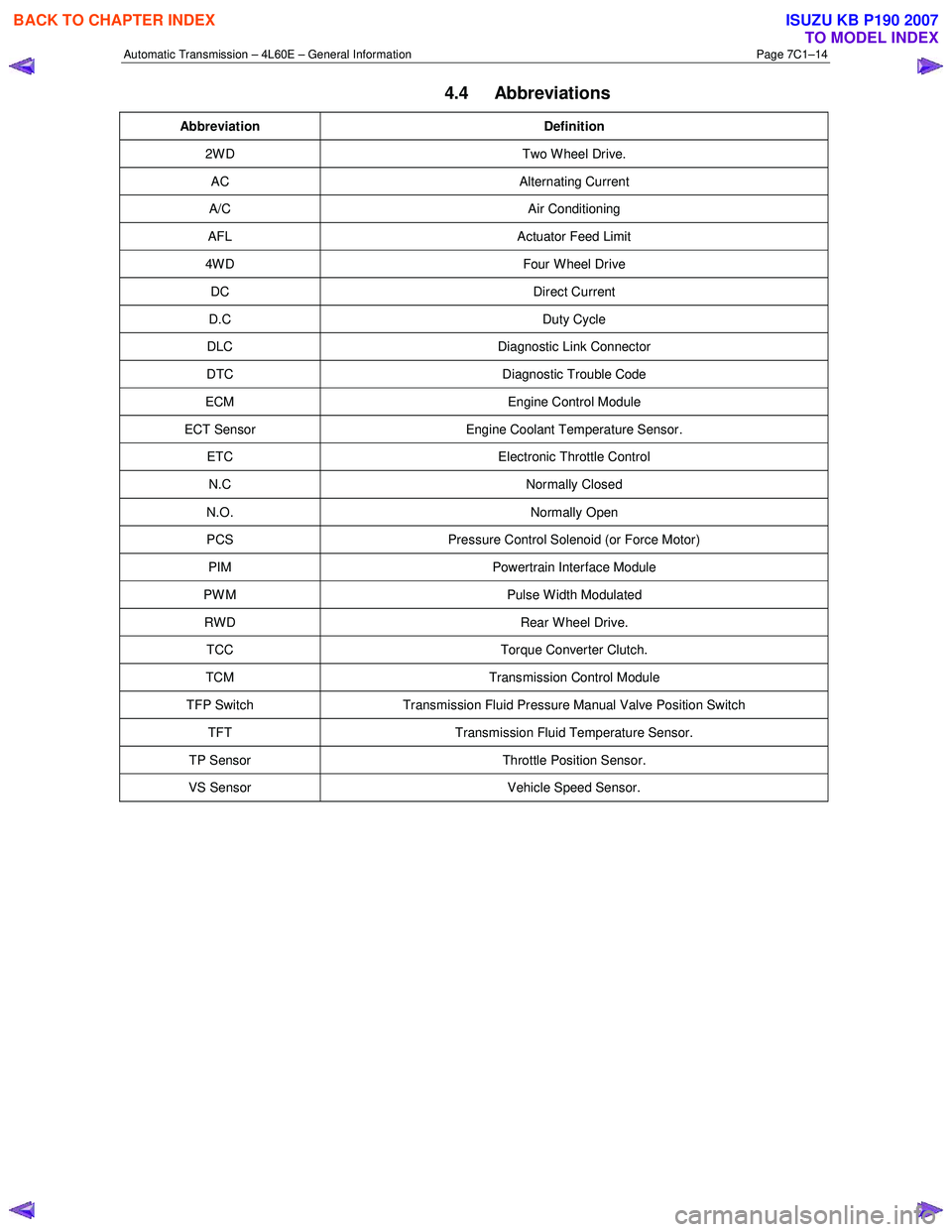
4.4 Abbreviations
Abbreviation Definition
2W D Two W heel Drive.
AC Alternating Current
A/C Air Conditioning
AFL Actuator Feed Limit
4W D Four W heel Drive
DC Direct Current
D.C Duty Cycle
DLC Diagnostic Link Connector
DTC Diagnostic Trouble Code
ECM Engine Control Module
ECT Sensor Engine Coolant Temperature Sensor.
ETC Electronic Throttle Control
N.C Normally Closed
N.O. Normally Open
PCS Pressure Control Solenoid (or Force Motor)
PIM Powertrain Interface Module
PW M Pulse W idth Modulated
RWD Rear Wheel Drive.
TCC Torque Converter Clutch.
TCM Transmission Control Module
TFP Switch Transmission Fluid Pressure Manual Valve Position Switch
TFT Transmission Fluid Temperature Sensor.
TP Sensor Throttle Position Sensor.
VS Sensor Vehicle Speed Sensor.
BACK TO CHAPTER INDEX
TO MODEL INDEX
ISUZU KB P190 2007
Page 3916 of 6020
Automatic Transmission – 4L60E – On-vehicle Servicing Page 7C4–3
1 General Information
This Section describes the removal and reinstallation procedures of the four speed 4L60E hydra-matic automatic
transmission as well as the service operations which can be performed with the transmission still fitted to the vehicle.
1.1 General Service Information
Description
The shift selector mechanism is linked to the transmission manual shaft with a selector cable. A heat protector is fitted
over the neutral start and back-up switch and manual shaft select lever.
For rear wheel drive (RWD) vehicles an extension housing is fitted to the rear of the transmission case.
Four wheel drive (4W D) vehicles have an adaptor housing and transfer case fitted to the rear of the transmission case,
for description and service operation refer to 7D Transfer Case and Adaptor Housing.
The four speed 4L60E hydra-matic automatic transmission is fitted with a filler tube, a breather hose and a vent pipe for
hot fluid overflow.
The transmission fluid is driven through a cooler within the radiator via the cooler line/hose assemblies to maintain
normal operating temperature.
Service Information
Throughout the service operations within this
Section, when handling retaining clips, using
compressed air or cleaning fluids, wear safety
equipment to avoid personal injury.
Refer to 7C1 Automatic Transmission – 4L60E – General Information for the following:
• information relating to mechanical and electrical operations,
• abbreviations, transmission specifications, special tools and torque wrench specifications,
• servicing, cleaning and inspection procedure recommendations.
It is essential to read and understand the General Information, W arnings, Cautions and Service Notes contained in that
same Section, before any service operation is performed on the four speed 4L60E hydra-matic automatic transmission or
any associated components.
Failure to comply with the procedures and service notes can affect the reliable and efficient operation of this automatic
transmission.
1.2 WARNINGS, CAUTIONS and NOTES
This Section contains various W ARNINGS, CAUTIONS and NOTE statements that you must observe carefully to reduce
the risk of death or injury during service, repair procedures or vehicle operation. Incorrect service or repair procedures
may damage the vehicle or cause operational faults. W ARNINGS, CAUTION and NOTE statements are not exhaustive.
GM HOLDEN LTD can not possibly warn of all the potentially hazardous consequences of failure to follow these
instructions.
Definition of WARNING, CAUTION and NOTE Statements
Diagnosis and repair procedures in this Section contain both general and specific W ARNING, CAUTION and NOTE
statements. GM HOLDEN LTD is dedicated to the presentation of service information that helps the technician to
diagnose and repair the systems necessary for proper operation of the vehicle. Certain procedures may present a hazard
to the technician if they are not followed in the recommended manner. W ARNING, CAUTION and NOTE statements are
designed to help prevent these hazards from occurring, but not all hazards can be foreseen.
BACK TO CHAPTER INDEX
TO MODEL INDEX
ISUZU KB P190 2007