2007 ISUZU KB P190 Alternator
[x] Cancel search: AlternatorPage 2157 of 6020
STARTING AND CHARGING SYSTEM 6D3-9
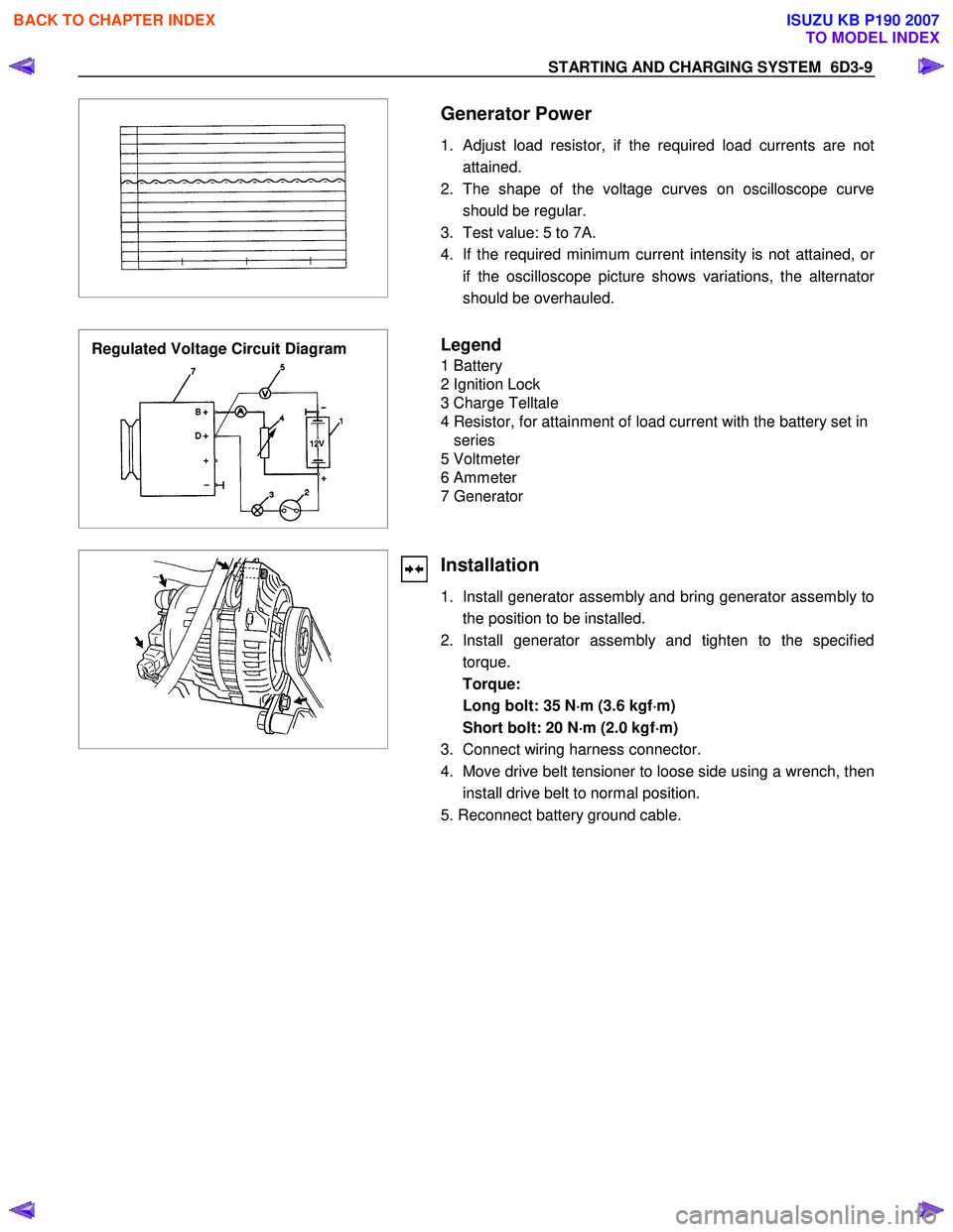
Generator Power
1. Adjust load resistor, if the required load currents are not attained.
2. The shape of the voltage curves on oscilloscope curve should be regular.
3. Test value: 5 to 7A.
4. If the required minimum current intensity is not attained, o
r
if the oscilloscope picture shows variations, the alternator
should be overhauled.
Regulated Voltage Circuit Diagram
Legend
1 Battery
2 Ignition Lock
3 Charge Telltale
4 Resistor, for attainment of load current with the battery set in series
5 Voltmeter
6 Ammeter
7 Generator
Installation
1. Install generator assembly and bring generator assembly to the position to be installed.
2. Install generator assembly and tighten to the specified torque.
Torque:
Long bolt: 35 N ⋅
⋅⋅
⋅
m (3.6 kgf ⋅
⋅⋅
⋅
m)
Short bolt: 20 N ⋅
⋅⋅
⋅
m (2.0 kgf ⋅
⋅⋅
⋅
m)
3. Connect wiring harness connector.
4. Move drive belt tensioner to loose side using a wrench, then install drive belt to normal position.
5. Reconnect battery ground cable.
BACK TO CHAPTER INDEX
TO MODEL INDEX
ISUZU KB P190 2007
Page 2158 of 6020
6D3-10 STARTING AND CHARGING SYSTEM
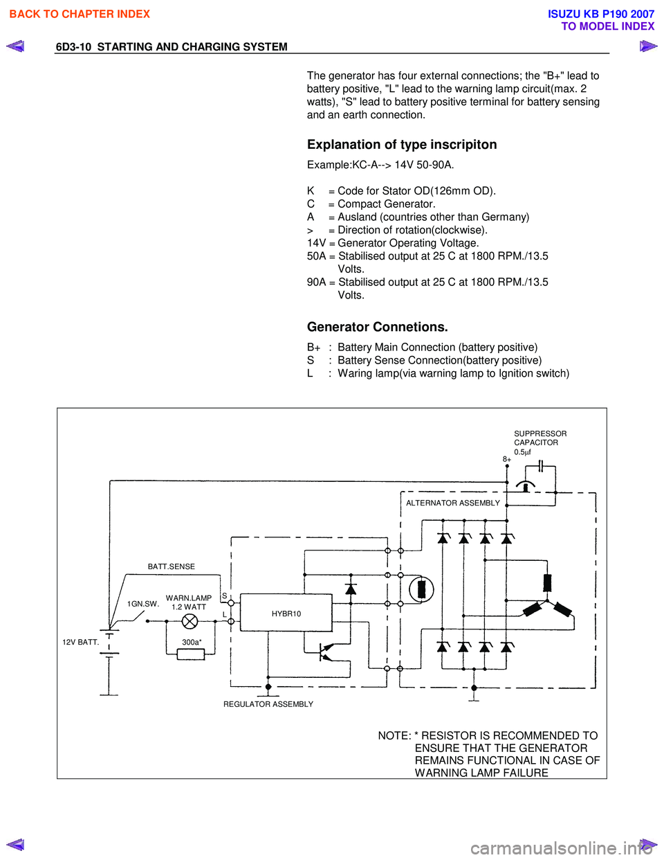
The generator has four external connections; the "B+" lead to
battery positive, "L" lead to the warning lamp circuit(max. 2
watts), "S" lead to battery positive terminal for battery sensing
and an earth connection.
Explanation of type inscripiton
Example:KC-A--> 14V 50-90A.
K = Code for Stator OD(126mm OD).
C = Compact Generator.
A = Ausland (countries other than Germany)
> = Direction of rotation(clockwise).
14V = Generator Operating Voltage.
50A = Stabilised output at 25 C at 1800 RPM./13.5
Volts.
90A = Stabilised output at 25 C at 1800 RPM./13.5
Volts.
Generator Connetions.
B+ : Battery Main Connection (battery positive)
S : Battery Sense Connection(battery positive)
L : W aring lamp(via warning lamp to Ignition switch)
BATT.SENSE
REGULATOR ASSEMBLYHYBR10 ALTERNATOR ASSEMBLY
12V BATT. 1GN.SW .
300a*
W ARN.LAMP
1.2 W ATT L
S 8+
SUPPRESSOR
CAPACITOR
0.5 µf
NOTE: * RESISTOR IS RECOMMENDED TO
ENSURE THAT THE GENERATOR
REMAINS FUNCTIONAL IN CASE OF
W ARNING LAMP FAILURE
BACK TO CHAPTER INDEX
TO MODEL INDEX
ISUZU KB P190 2007
Page 3307 of 6020
Engine Management – V6 – Diagnostics Page 6C1-2–29
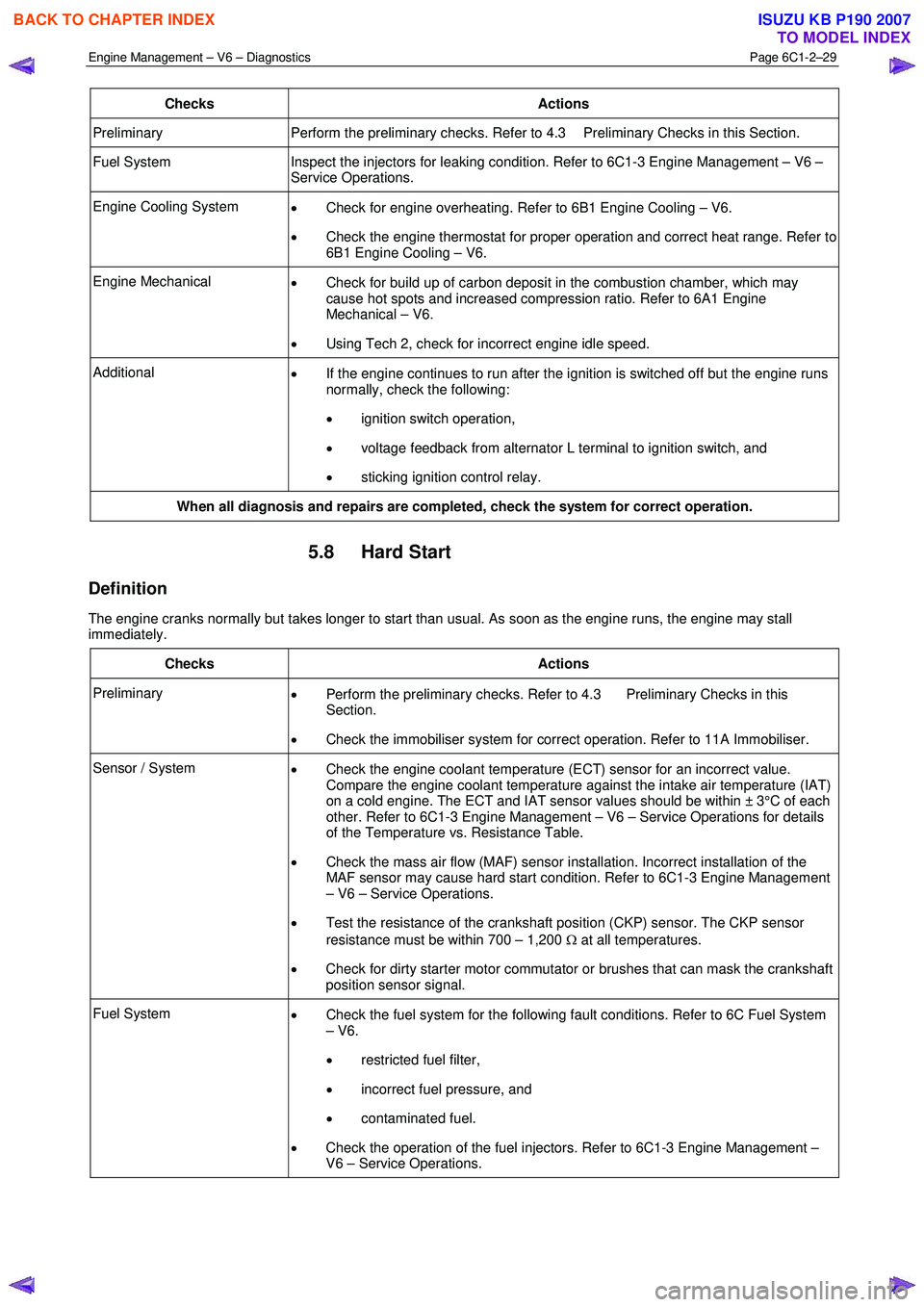
Checks Actions
Preliminary Perform the preliminary checks. Refer to 4.3 Preliminary Checks in this Section.
Fuel System Inspect the injectors for leaking condition. Refer to 6C1-3 Engine Management – V6 –
Service Operations.
Engine Cooling System • Check for engine overheating. Refer to 6B1 Engine Cooling – V6.
• Check the engine thermostat for proper operation and correct heat range. Refer to
6B1 Engine Cooling – V6.
Engine Mechanical • Check for build up of carbon deposit in the combustion chamber, which may
cause hot spots and increased compression ratio. Refer to 6A1 Engine
Mechanical – V6.
• Using Tech 2, check for incorrect engine idle speed.
Additional
• If the engine continues to run after the ignition is switched off but the engine runs
normally, check the following:
• ignition switch operation,
• voltage feedback from alternator L terminal to ignition switch, and
• sticking ignition control relay.
When all diagnosis and repairs are completed, check the system for correct operation.
5.8 Hard Start
Definition
The engine cranks normally but takes longer to start than usual. As soon as the engine runs, the engine may stall
immediately.
Checks Actions
Preliminary • Perform the preliminary checks. Refer to 4.3 Preliminary Checks in this
Section.
• Check the immobiliser system for correct operation. Refer to 11A Immobiliser.
Sensor / System
• Check the engine coolant temperature (ECT) sensor for an incorrect value.
Compare the engine coolant temperature against the intake air temperature (IAT)
on a cold engine. The ECT and IAT sensor values should be within ± 3°C of each
other. Refer to 6C1-3 Engine Management – V6 – Service Operations for details
of the Temperature vs. Resistance Table.
• Check the mass air flow (MAF) sensor installation. Incorrect installation of the
MAF sensor may cause hard start condition. Refer to 6C1-3 Engine Management
– V6 – Service Operations.
• Test the resistance of the crankshaft position (CKP) sensor. The CKP sensor
resistance must be within 700 – 1,200 Ω at all temperatures.
• Check for dirty starter motor commutator or brushes that can mask the crankshaft
position sensor signal.
Fuel System • Check the fuel system for the following fault conditions. Refer to 6C Fuel System
– V6.
• restricted fuel filter,
• incorrect fuel pressure, and
• contaminated fuel.
• Check the operation of the fuel injectors. Refer to 6C1-3 Engine Management –
V6 – Service Operations.
BACK TO CHAPTER INDEX
TO MODEL INDEX
ISUZU KB P190 2007
Page 3334 of 6020
Engine Management – V6 – Diagnostics Page 6C1-2–56
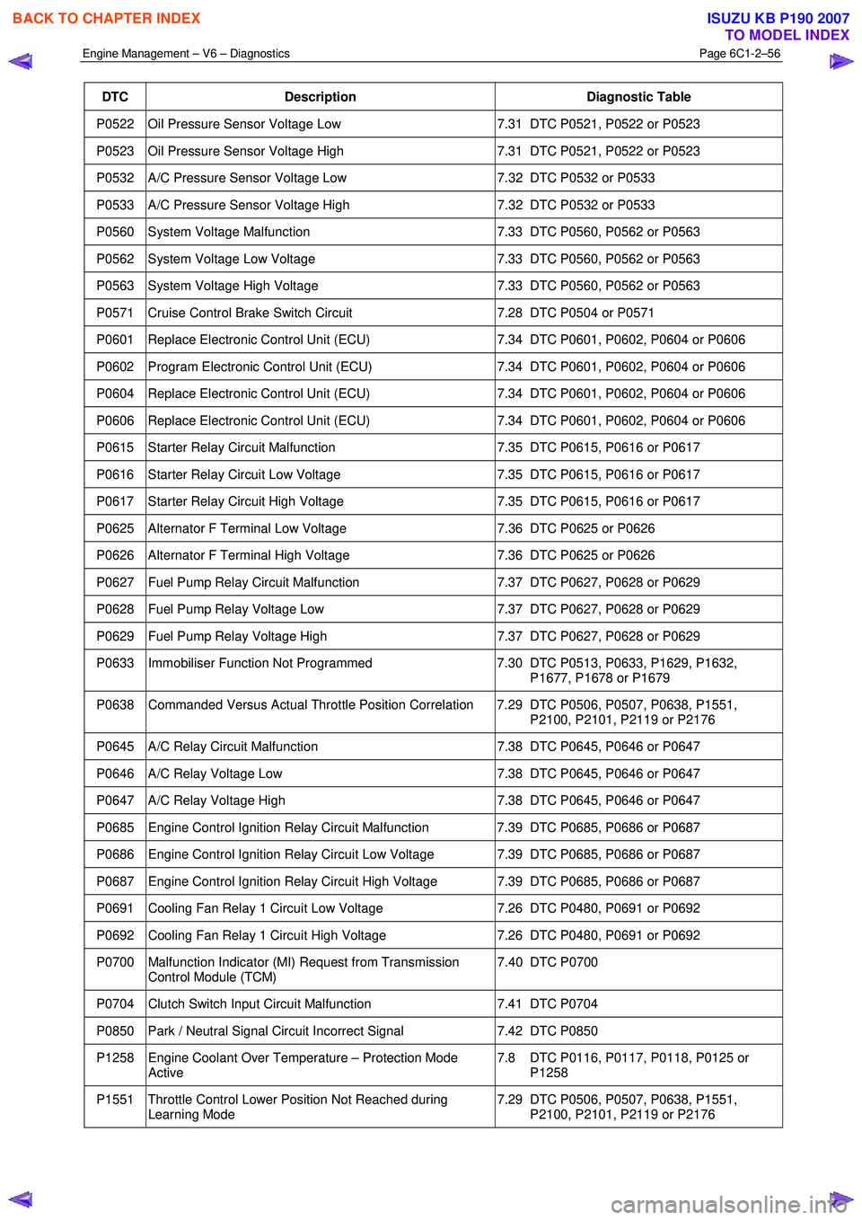
DTC Description Diagnostic Table
P0522 Oil Pressure Sensor Voltage Low 7.31 DTC P0521, P0522 or P0523
P0523 Oil Pressure Sensor Voltage High 7.31 DTC P0521, P0522 or P0523
P0532 A/C Pressure Sensor Voltage Low 7.32 DTC P0532 or P0533
P0533 A/C Pressure Sensor Voltage High 7.32 DTC P0532 or P0533
P0560 System Voltage Malfunction 7.33 DTC P0560, P0562 or P0563
P0562 System Voltage Low Voltage 7.33 DTC P0560, P0562 or P0563
P0563 System Voltage High Voltage 7.33 DTC P0560, P0562 or P0563
P0571 Cruise Control Brake Switch Circuit 7.28 DTC P0504 or P0571
P0601 Replace Electronic Control Unit (ECU) 7.34 DTC P0601, P0602, P0604 or P0606
P0602 Program Electronic Control Unit (ECU) 7.34 DTC P0601, P0602, P0604 or P0606
P0604 Replace Electronic Control Unit (ECU) 7.34 DTC P0601, P0602, P0604 or P0606
P0606 Replace Electronic Control Unit (ECU) 7.34 DTC P0601, P0602, P0604 or P0606
P0615 Starter Relay Circuit Malfunction 7.35 DTC P0615, P0616 or P0617
P0616 Starter Relay Circuit Low Voltage 7.35 DTC P0615, P0616 or P0617
P0617 Starter Relay Circuit High Voltage 7.35 DTC P0615, P0616 or P0617
P0625 Alternator F Terminal Low Voltage 7.36 DTC P0625 or P0626
P0626 Alternator F Terminal High Voltage 7.36 DTC P0625 or P0626
P0627 Fuel Pump Relay Circuit Malfunction 7.37 DTC P0627, P0628 or P0629
P0628 Fuel Pump Relay Voltage Low 7.37 DTC P0627, P0628 or P0629
P0629 Fuel Pump Relay Voltage High 7.37 DTC P0627, P0628 or P0629
P0633 Immobiliser Function Not Programmed 7.30 DTC P0513, P0633, P1629, P1632,
P1677, P1678 or P1679
P0638 Commanded Versus Actual Throttle Position Correlation 7.29 DTC P0506, P0507, P0638, P1551, P2100, P2101, P2119 or P2176
P0645 A/C Relay Circuit Malfunction 7.38 DTC P0645, P0646 or P0647
P0646 A/C Relay Voltage Low 7.38 DTC P0645, P0646 or P0647
P0647 A/C Relay Voltage High 7.38 DTC P0645, P0646 or P0647
P0685 Engine Control Ignition Relay Circuit Malfunction 7.39 DTC P0685, P0686 or P0687
P0686 Engine Control Ignition Relay Circuit Low Voltage 7.39 DTC P0685, P0686 or P0687
P0687 Engine Control Ignition Relay Circuit High Voltage 7.39 DTC P0685, P0686 or P0687
P0691 Cooling Fan Relay 1 Circuit Low Voltage 7.26 DTC P0480, P0691 or P0692
P0692 Cooling Fan Relay 1 Circuit High Voltage 7.26 DTC P0480, P0691 or P0692
P0700 Malfunction Indicator (MI) Request from Transmission
Control Module (TCM) 7.40 DTC P0700
P0704 Clutch Switch Input Circuit Malfunction
7.41 DTC P0704
P0850 Park / Neutral Signal Circuit Incorrect Signal 7.42 DTC P0850
P1258 Engine Coolant Over Temperature – Protection Mode
Active 7.8 DTC P0116, P0117, P0118, P0125 or
P1258
P1551 Throttle Control Lower Position Not Reached during Learning Mode 7.29 DTC P0506, P0507, P0638, P1551,
P2100, P2101, P2119 or P2176
BACK TO CHAPTER INDEX
TO MODEL INDEX
ISUZU KB P190 2007
Page 3335 of 6020
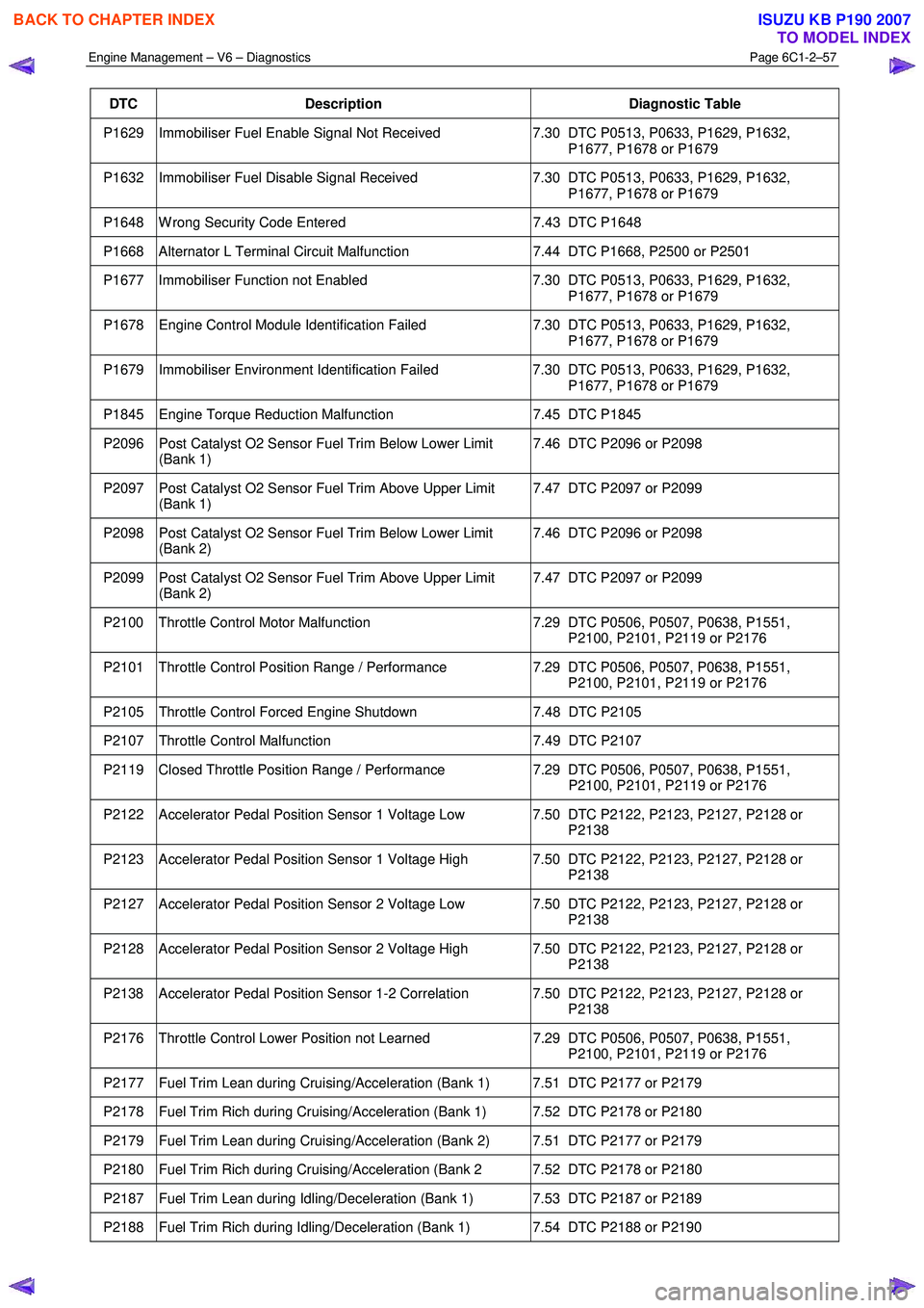
Engine Management – V6 – Diagnostics Page 6C1-2–57
DTC Description Diagnostic Table
P1629 Immobiliser Fuel Enable Signal Not Received 7.30 DTC P0513, P0633, P1629, P1632,
P1677, P1678 or P1679
P1632 Immobiliser Fuel Disable Signal Received 7.30 DTC P0513, P0633, P1629, P1632,
P1677, P1678 or P1679
P1648 W rong Security Code Entered 7.43 DTC P1648
P1668 Alternator L Terminal Circuit Malfunction 7.44 DTC P1668, P2500 or P2501
P1677 Immobiliser Function not Enabled 7.30 DTC P0513, P0633, P1629, P1632,
P1677, P1678 or P1679
P1678 Engine Control Module Identification Failed 7.30 DTC P0513, P0633, P1629, P1632,
P1677, P1678 or P1679
P1679 Immobiliser Environment Identification Failed 7.30 DTC P0513, P0633, P1629, P1632,
P1677, P1678 or P1679
P1845 Engine Torque Reduction Malfunction 7.45 DTC P1845
P2096 Post Catalyst O2 Sensor Fuel Trim Below Lower Limit
(Bank 1) 7.46 DTC P2096 or P2098
P2097 Post Catalyst O2 Sensor Fuel Trim Above Upper Limit
(Bank 1) 7.47 DTC P2097 or P2099
P2098 Post Catalyst O2 Sensor Fuel Trim Below Lower Limit
(Bank 2) 7.46 DTC P2096 or P2098
P2099 Post Catalyst O2 Sensor Fuel Trim Above Upper Limit
(Bank 2) 7.47 DTC P2097 or P2099
P2100 Throttle Control Motor Malfunction
7.29 DTC P0506, P0507, P0638, P1551,
P2100, P2101, P2119 or P2176
P2101 Throttle Control Position Range / Performance 7.29 DTC P0506, P0507, P0638, P1551,
P2100, P2101, P2119 or P2176
P2105 Throttle Control Forced Engine Shutdown 7.48 DTC P2105
P2107 Throttle Control Malfunction 7.49 DTC P2107
P2119 Closed Throttle Position Range / Performance 7.29 DTC P0506, P0507, P0638, P1551,
P2100, P2101, P2119 or P2176
P2122 Accelerator Pedal Position Sensor 1 Voltage Low 7.50 DTC P2122, P2123, P2127, P2128 or P2138
P2123 Accelerator Pedal Position Sensor 1 Voltage High 7.50 DTC P2122, P2123, P2127, P2128 or P2138
P2127 Accelerator Pedal Position Sensor 2 Voltage Low 7.50 DTC P2122, P2123, P2127, P2128 or P2138
P2128 Accelerator Pedal Position Sensor 2 Voltage High 7.50 DTC P2122, P2123, P2127, P2128 or P2138
P2138 Accelerator Pedal Position Sensor 1-2 Correlation 7.50 DTC P2122, P2123, P2127, P2128 or P2138
P2176 Throttle Control Lower Position not Learned 7.29 DTC P0506, P0507, P0638, P1551,
P2100, P2101, P2119 or P2176
P2177 Fuel Trim Lean during Cruising/Acceleration (Bank 1) 7.51 DTC P2177 or P2179
P2178 Fuel Trim Rich during Cruising/Acceleration (Bank 1) 7.52 DTC P2178 or P2180
P2179 Fuel Trim Lean during Cruising/Acceleration (Bank 2) 7.51 DTC P2177 or P2179
P2180 Fuel Trim Rich during Cruising/Acceleration (Bank 2 7.52 DTC P2178 or P2180
P2187 Fuel Trim Lean during Idling/Deceleration (Bank 1) 7.53 DTC P2187 or P2189
P2188 Fuel Trim Rich during Idling/Deceleration (Bank 1) 7.54 DTC P2188 or P2190
BACK TO CHAPTER INDEX
TO MODEL INDEX
ISUZU KB P190 2007
Page 3338 of 6020
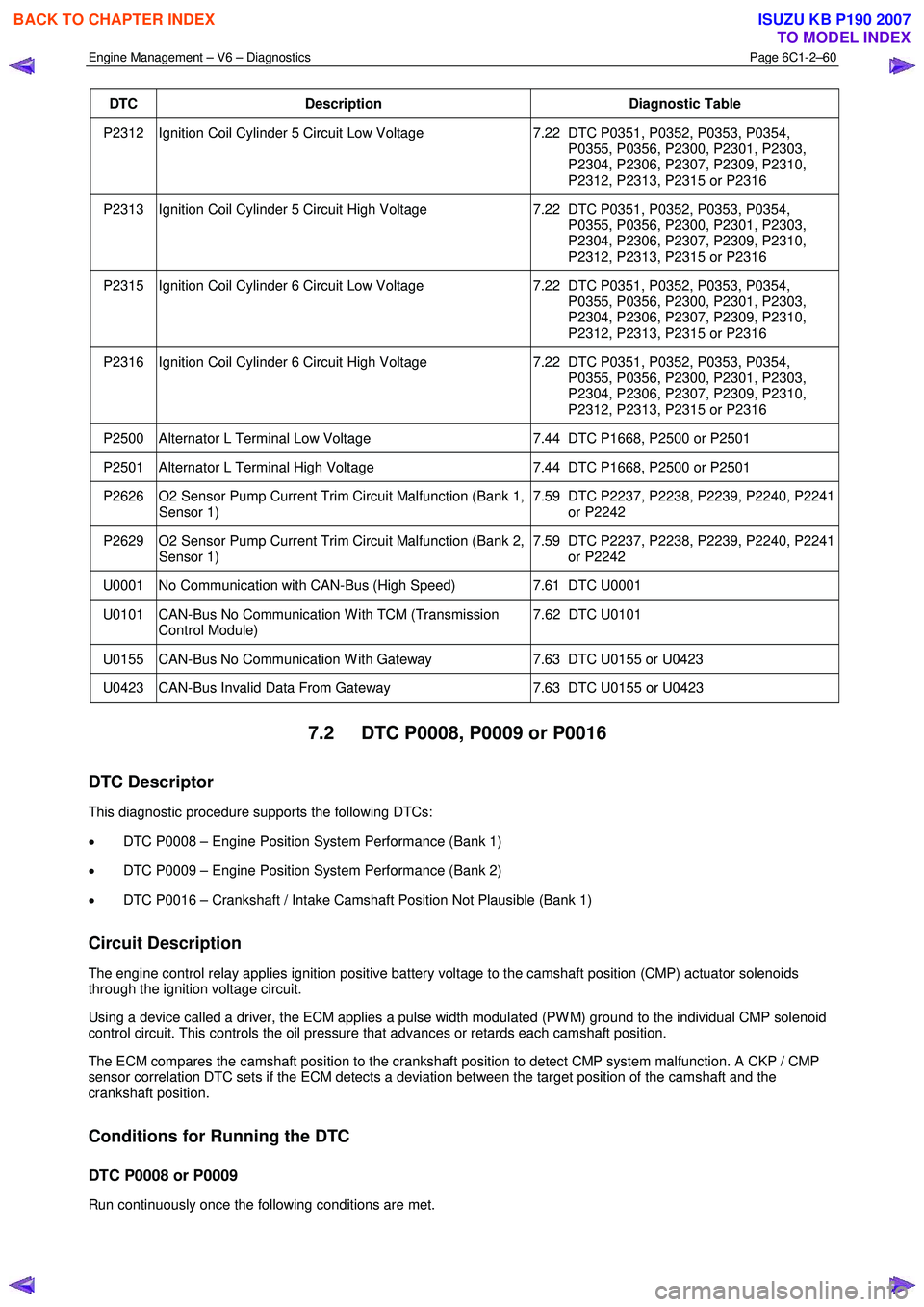
Engine Management – V6 – Diagnostics Page 6C1-2–60
DTC Description Diagnostic Table
P2312 Ignition Coil Cylinder 5 Circuit Low Voltage 7.22 DTC P0351, P0352, P0353, P0354,
P0355, P0356, P2300, P2301, P2303,
P2304, P2306, P2307, P2309, P2310,
P2312, P2313, P2315 or P2316
P2313 Ignition Coil Cylinder 5 Circuit High Voltage 7.22 DTC P0351, P0352, P0353, P0354,
P0355, P0356, P2300, P2301, P2303,
P2304, P2306, P2307, P2309, P2310,
P2312, P2313, P2315 or P2316
P2315 Ignition Coil Cylinder 6 Circuit Low Voltage 7.22 DTC P0351, P0352, P0353, P0354,
P0355, P0356, P2300, P2301, P2303,
P2304, P2306, P2307, P2309, P2310,
P2312, P2313, P2315 or P2316
P2316 Ignition Coil Cylinder 6 Circuit High Voltage 7.22 DTC P0351, P0352, P0353, P0354,
P0355, P0356, P2300, P2301, P2303,
P2304, P2306, P2307, P2309, P2310,
P2312, P2313, P2315 or P2316
P2500 Alternator L Terminal Low Voltage 7.44 DTC P1668, P2500 or P2501
P2501 Alternator L Terminal High Voltage 7.44 DTC P1668, P2500 or P2501
P2626 O2 Sensor Pump Current Trim Circuit Malfunction (Bank 1,
Sensor 1) 7.59 DTC P2237, P2238, P2239, P2240, P2241
or P2242
P2629 O2 Sensor Pump Current Trim Circuit Malfunction (Bank 2, Sensor 1) 7.59 DTC P2237, P2238, P2239, P2240, P2241
or P2242
U0001 No Communication with CAN-Bus (High Speed) 7.61 DTC U0001
U0101 CAN-Bus No Communication W ith TCM (Transmission
Control Module) 7.62 DTC U0101
U0155 CAN-Bus No Communication W ith Gateway
7.63 DTC U0155 or U0423
U0423 CAN-Bus Invalid Data From Gateway 7.63 DTC U0155 or U0423
7.2 DTC P0008, P0009 or P0016
DTC Descriptor
This diagnostic procedure supports the following DTCs:
• DTC P0008 – Engine Position System Performance (Bank 1)
• DTC P0009 – Engine Position System Performance (Bank 2)
• DTC P0016 – Crankshaft / Intake Camshaft Position Not Plausible (Bank 1)
Circuit Description
The engine control relay applies ignition positive battery voltage to the camshaft position (CMP) actuator solenoids
through the ignition voltage circuit.
Using a device called a driver, the ECM applies a pulse width modulated (PW M) ground to the individual CMP solenoid
control circuit. This controls the oil pressure that advances or retards each camshaft position.
The ECM compares the camshaft position to the crankshaft position to detect CMP system malfunction. A CKP / CMP
sensor correlation DTC sets if the ECM detects a deviation between the target position of the camshaft and the
crankshaft position.
Conditions for Running the DTC
DTC P0008 or P0009
Run continuously once the following conditions are met.
BACK TO CHAPTER INDEX
TO MODEL INDEX
ISUZU KB P190 2007
Page 3431 of 6020
Engine Management – V6 – Diagnostics Page 6C1-2–153
Step Action Yes No
When all diagnosis and repairs are completed, check the system for correct operation.
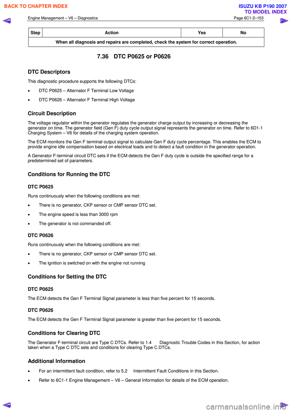
7.36 DTC P0625 or P0626
DTC Descriptors
This diagnostic procedure supports the following DTCs:
• DTC P0625 – Alternator F Terminal Low Voltage
• DTC P0626 – Alternator F Terminal High Voltage
Circuit Description
The voltage regulator within the generator regulates the generator charge output by increasing or decreasing the
generator on time. The generator field (Gen F) duty cycle output signal represents the generator on time. Refer to 6D1-1
Charging System – V6 for details of the charging system operation.
The ECM monitors the Gen F terminal output signal to calculate Gen F duty cycle percentage. This enables the ECM to
provide engine idle compensation based on electrical loads and to detect a fault condition in the generator operation.
A Generator F-terminal circuit DTC sets if the ECM detects the Gen F duty cycle is outside the specified range for a
predetermined set of parameters.
Conditions for Running the DTC
DTC P0625
Runs continuously when the following conditions are met:
• There is no generator, CKP sensor or CMP sensor DTC set.
• The engine speed is less than 3000 rpm
• The generator is not commanded off.
DTC P0626
Runs continuously when the following conditions are met:
• There is no generator, CKP sensor or CMP sensor DTC set.
• The ignition is switched on with the engine not running
Conditions for Setting the DTC
DTC P0625
The ECM detects the Gen F Terminal Signal parameter is less than five percent for 15 seconds.
DTC P0626
The ECM detects the Gen F Terminal Signal parameter is greater than five percent for 15 seconds.
Conditions for Clearing DTC
The Generator F-terminal circuit are Type C DTCs. Refer to 1.4 Diagnostic Trouble Codes in this Section, for action
taken when a Type C DTC sets and conditions for clearing Type C DTCs.
Additional Information
• For an intermittent fault condition, refer to 5.2 Intermittent Fault Conditions in this Section.
• Refer to 6C1-1 Engine Management – V6 – General Information for details of the ECM operation.
BACK TO CHAPTER INDEX
TO MODEL INDEX
ISUZU KB P190 2007
Page 3502 of 6020
Engine Management – V6 – Diagnostics Page 6C1-2–224
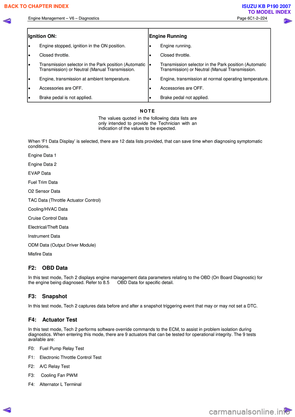
Ignition ON:
• Engine stopped, ignition in the ON position.
• Closed throttle.
• Transmission selector in the Park position (Automatic
Transmission) or Neutral (Manual Transmission.
• Engine, transmission at ambient temperature.
• Accessories are OFF.
• Brake pedal is not applied.
Engine Running
• Engine running.
• Closed throttle.
• Transmission selector in the Park position (Automatic
Transmission) or Neutral (Manual Transmission.
• Engine, transmission at normal operating temperature.
• Accessories are OFF.
• Brake pedal not applied.
NOTE
The values quoted in the following data lists are
only intended to provide the Technician with an
indication of the values to be expected.
W hen ‘F1 Data Display’ is selected, there are 12 data lists provided, that can save time when diagnosing symptomatic
conditions.
Engine Data 1
Engine Data 2
EVAP Data
Fuel Trim Data
O2 Sensor Data
TAC Data (Throttle Actuator Control)
Cooling/HVAC Data
Cruise Control Data
Electrical/Theft Data
Instrument Data
ODM Data (Output Driver Module)
Misfire Data
F2: OBD Data
In this test mode, Tech 2 displays engine management data parameters relating to the OBD (On Board Diagnostic) for
the engine being diagnosed. Refer to 8.5 OBD Data for specific detail.
F3: Snapshot
In this test mode, Tech 2 captures data before and after a snapshot triggering event that may or may not set a DTC.
F4: Actuator Test
In this test mode, Tech 2 performs software override commands to the ECM, to assist in problem isolation during
diagnostics. W hen entering this mode, there are 9 actuators that can be tested for operational integrity. The 9 tests
available are:
F0: Fuel Pump Relay Test
F1: Electronic Throttle Control Test
F2: A/C Relay Test
F3: Cooling Fan PW M
F4: Alternator L Terminal
BACK TO CHAPTER INDEX
TO MODEL INDEX
ISUZU KB P190 2007