2007 ISUZU KB P190 Alternator
[x] Cancel search: AlternatorPage 2040 of 6020
6A-26 ENGINE MECHANICAL (C24SE)
OPERATIONS ON INSTALLED ENGINE
SEALING OPERATIONS
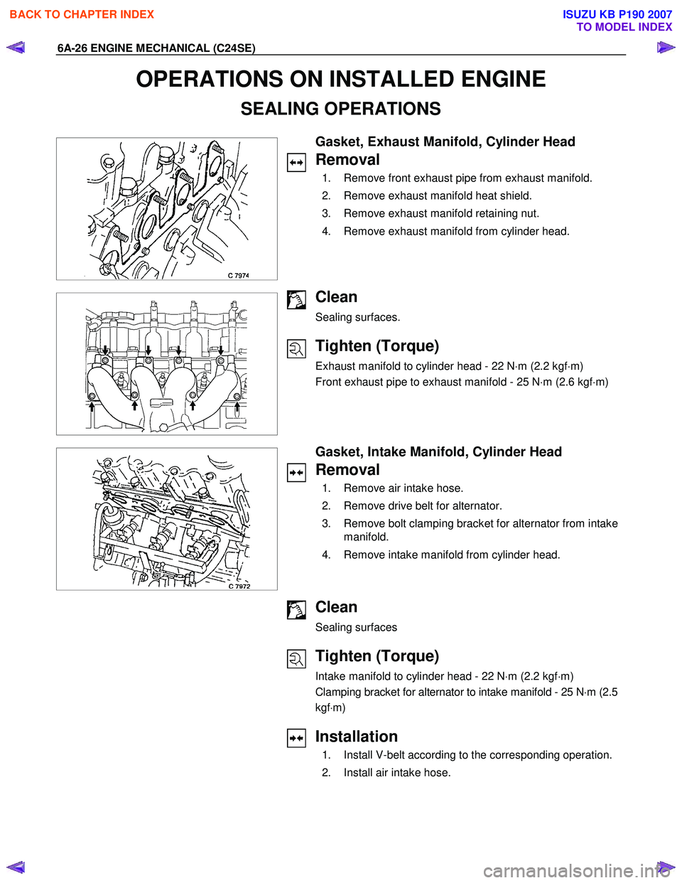
Gasket, Exhaust Manifold, Cylinder Head
Removal
1. Remove front exhaust pipe from exhaust manifold.
2. Remove exhaust manifold heat shield.
3. Remove exhaust manifold retaining nut.
4. Remove exhaust manifold from cylinder head.
Clean
Sealing surfaces.
Tighten (Torque)
Exhaust manifold to cylinder head - 22 N ⋅m (2.2 kgf ⋅m)
Front exhaust pipe to exhaust manifold - 25 N ⋅m (2.6 kgf ⋅m)
Gasket, Intake Manifold, Cylinder Head
Removal
1. Remove air intake hose.
2. Remove drive belt for alternator.
3. Remove bolt clamping bracket for alternator from intake manifold.
4. Remove intake manifold from cylinder head.
Clean
Sealing surfaces
Tighten (Torque)
Intake manifold to cylinder head - 22 N ⋅m (2.2 kgf ⋅m)
Clamping bracket for alternator to intake manifold - 25 N ⋅m (2.5
kgf ⋅m)
Installation
1. Install V-belt according to the corresponding operation.
2. Install air intake hose.
BACK TO CHAPTER INDEX
TO MODEL INDEX
ISUZU KB P190 2007
Page 2049 of 6020
ENGINE MECHANICAL (C24SE) 6A-35
Camshaft Housing, Removal and
Installation
Cylinder Head
Important!
Remove cylinder head only from cold engine (room
temperature).
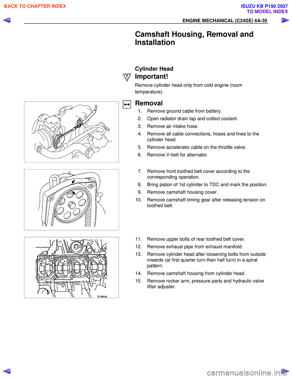
Removal
1. Remove ground cable from battery.
2. Open radiator drain tap and collect coolant.
3. Remove air intake hose.
4. Remove all cable connections, hoses and lines to the cylinder head.
5. Remove accelerator cable on the throttle valve.
6. Remove V-belt for alternator.
7. Remove front toothed belt cover according to the
corresponding operation.
8. Bring piston of 1st cylinder to TDC and mark the position.
9. Remove camshaft housing cover.
10. Remove camshaft timing gear after releasing tension on toothed belt.
11. Remove upper bolts of rear toothed belt cover.
12. Remove exhaust pipe from exhaust manifold.
13. Remove cylinder head after loosening bolts from outside inwards (at first quarter turn then half turn) in a spiral
pattern.
14. Remove camshaft housing from cylinder head.
15. Remove rocker arm, pressure parts and hydraulic valve lifter adjuster.
BACK TO CHAPTER INDEX
TO MODEL INDEX
ISUZU KB P190 2007
Page 2053 of 6020

ENGINE MECHANICAL (C24SE) 6A-39
Camshaft Housing, Check for Plane Surface
Clean
Sealing surfaces.
Inspection
Check length and width of sealing surface for deformation and
diagnosis for warpage and use straight edge feeler gauge.
Measure
Height of camshaft housing (sealing surface to sealing
surface).
Dimension I: (74.0 mm)
Cylinder Head, Removal and Installation
Important
Only remove cylinder head with engine cold (room
temperature).
Removal
1. Remove the alternator, power steering and V-belts.
Removal
2. Loosen the fastening bolts from alternator.
3. Loosen the lower alternator fastening bolt by swinging the alternator to the rear.
Removal
4. Remove the front toothed belt cover.
5. Remove the toothed belt from camshaft pulley.
See operation "Timing Check and Adjust".
BACK TO CHAPTER INDEX
TO MODEL INDEX
ISUZU KB P190 2007
Page 2056 of 6020
6A-42 ENGINE MECHANICAL (C24SE)
Installation
1. Install the fastening bolts.
2. Loosen the lower alternator fastening bolt.
3. Install the alternator, power steering and V-belts.
Cylinder Head, Disassemble and Assemble
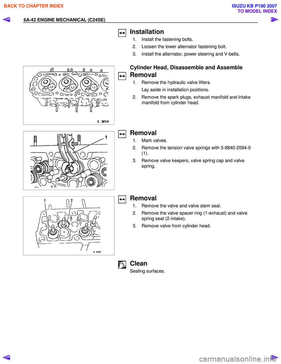
Removal
1. Remove the hydraulic valve lifters.
Lay aside in installation positions.
2. Remove the spark plugs, exhaust manifold and intake manifold from cylinder head.
Removal
1. Mark valves.
2. Remove the tension valve springs with 5-8840-2594-0 (1).
3. Remove valve keepers, valve spring cap and valve spring.
Removal
1. Remove the valve and valve stem seal.
2. Remove the valve spacer ring (1-exhaust) and valve spring seat (2-intake).
3. Remove valve from cylinder head.
Clean
Sealing surfaces.
BACK TO CHAPTER INDEX
TO MODEL INDEX
ISUZU KB P190 2007
Page 2081 of 6020
ENGINE MECHANICAL (C24SE) 6A-67
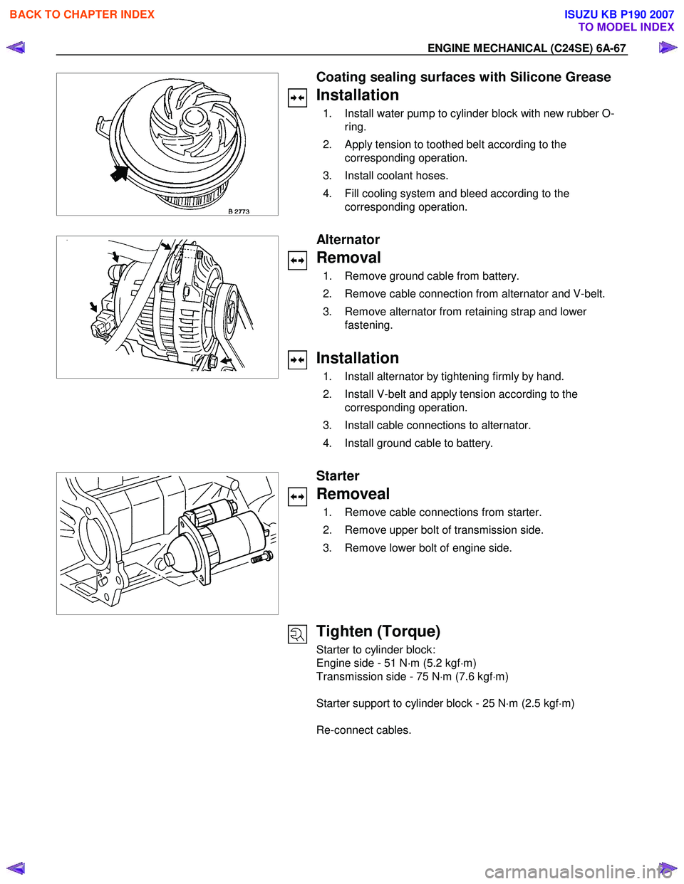
Coating sealing surfaces with Silicone Grease
Installation
1. Install water pump to cylinder block with new rubber O-ring.
2. Apply tension to toothed belt according to the corresponding operation.
3. Install coolant hoses.
4. Fill cooling system and bleed according to the corresponding operation.
Alternator
Removal
1. Remove ground cable from battery.
2. Remove cable connection from alternator and V-belt.
3. Remove alternator from retaining strap and lower fastening.
Installation
1. Install alternator by tightening firmly by hand.
2. Install V-belt and apply tension according to the corresponding operation.
3. Install cable connections to alternator.
4. Install ground cable to battery.
Starter
Removeal
1. Remove cable connections from starter.
2. Remove upper bolt of transmission side.
3. Remove lower bolt of engine side.
Tighten (Torque)
Starter to cylinder block:
Engine side - 51 N ⋅m (5.2 kgf ⋅m)
Transmission side - 75 N ⋅m (7.6 kgf ⋅m)
Starter support to cylinder block - 25 N ⋅m (2.5 kgf ⋅m)
Re-connect cables.
BACK TO CHAPTER INDEX
TO MODEL INDEX
ISUZU KB P190 2007
Page 2082 of 6020
6A-68 ENGINE MECHANICAL (C24SE)
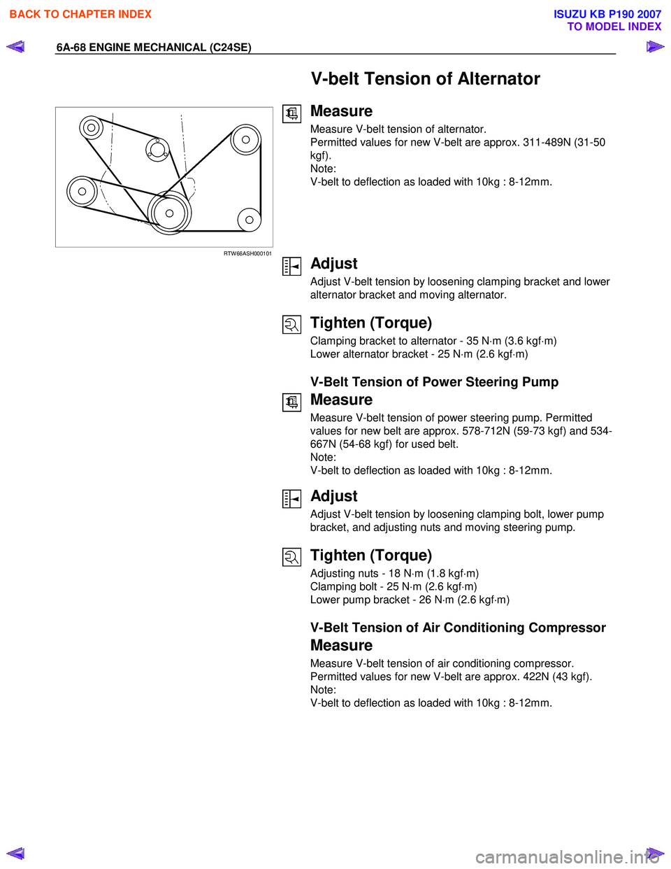
V-belt Tension of Alternator
RTW 66ASH000101
Measure
Measure V-belt tension of alternator.
Permitted values for new V-belt are approx. 311-489N (31-50
kgf).
Note:
V-belt to deflection as loaded with 10kg : 8-12mm.
Adjust
Adjust V-belt tension by loosening clamping bracket and lower
alternator bracket and moving alternator.
Tighten (Torque)
Clamping bracket to alternator - 35 N ⋅m (3.6 kgf ⋅m)
Lower alternator bracket - 25 N ⋅m (2.6 kgf ⋅m)
V-Belt Tension of Power Steering Pump
Measure
Measure V-belt tension of power steering pump. Permitted
values for new belt are approx. 578-712N (59-73 kgf) and 534-
667N (54-68 kgf) for used belt.
Note:
V-belt to deflection as loaded with 10kg : 8-12mm.
Adjust
Adjust V-belt tension by loosening clamping bolt, lower pump
bracket, and adjusting nuts and moving steering pump.
Tighten (Torque)
Adjusting nuts - 18 N ⋅m (1.8 kgf ⋅m)
Clamping bolt - 25 N ⋅m (2.6 kgf ⋅m)
Lower pump bracket - 26 N ⋅m (2.6 kgf ⋅m)
V-Belt Tension of Air Conditioning Compressor
Measure
Measure V-belt tension of air conditioning compressor.
Permitted values for new V-belt are approx. 422N (43 kgf).
Note:
V-belt to deflection as loaded with 10kg : 8-12mm.
BACK TO CHAPTER INDEX
TO MODEL INDEX
ISUZU KB P190 2007
Page 2102 of 6020
6A-88 ENGINE MECHANICAL (C24SE)
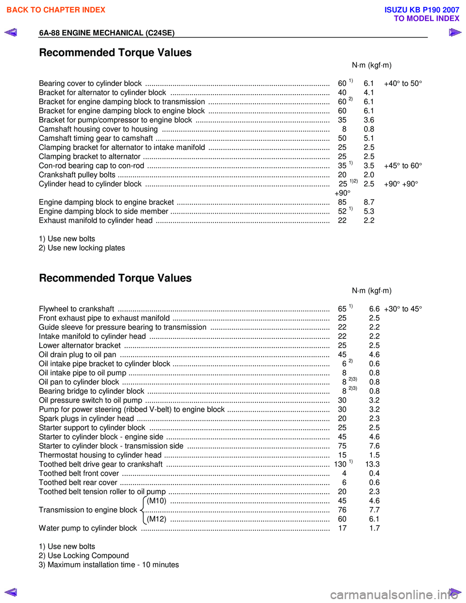
Recommended Torque Values
N⋅m (kgf ⋅m)
Bearing cover to cylinder block ........................................................................................ 60
1) 6.1 +40 ° to 50 °
Bracket for alternator to cylinder block ............................................................................ 40 4.1
Bracket for engine damping block to transmission .......................................................... 60
2) 6.1
Bracket for engine damping block to engine block .......................................................... 60 6.1
Bracket for pump/compressor to engine block ................................................................ 35 3.6
Camshaft housing cover to housing ................................................................................ 8 0.8
Camshaft timing gear to camshaft ................................................................................... 50 5.1
Clamping bracket for alternator to intake manifold .......................................................... 25 2.5
Clamping bracket to alternator ......................................................................................... 25 2.5
Con-rod bearing cap to con-rod ....................................................................................... 35
1) 3.5 +45 ° to 60 °
Crankshaft pulley bolts ..................................................................................................... 2 0 2.0
Cylinder head to cylinder block ........................................................................................ 25
1)2) 2.5 +90 ° +90 °
+90 °
Engine damping block to engine bracket ......................................................................... 85 8.7
Engine damping block to side member ............................................................................ 52
1) 5.3
Exhaust manifold to cylinder head ................................................................................... 22 2.2
1) Use new bolts
2) Use new locking plates
Recommended Torque Values
N⋅m (kgf ⋅m)
Flywheel to crankshaft ..................................................................................................... 65
1) 6.6 +30° to 45 °
Front exhaust pipe to exhaust manifold ........................................................................... 25 2.5
Guide sleeve for pressure bearing to transmission ......................................................... 22 2.2
Intake manifold to cylinder head ...................................................................................... 22 2.2
Lower alternator bracket .................................................................................................. 25 2.5
Oil drain plug to oil pan .................................................................................................... 45 4.6
Oil intake pipe bracket to cylinder block ........................................................................... 6
2) 0.6
Oil intake pipe to oil pump ................................................................................................ 8 0.8
Oil pan to cylinder block ................................................................................................... 8
2)3) 0.8
Bearing bridge to cylinder block ....................................................................................... 8 2)3) 0.8
Oil pressure switch to oil pump ........................................................................................ 30 3.2
Pump for power steering (ribbed V-belt) to engine block ................................................. 30 3.2
Spark plugs in cylinder head ............................................................................................ 20 2. 3
Starter support to cylinder block ...................................................................................... 25 2.5
Starter to cylinder block - engine side .............................................................................. 45 4.6
Starter to cylinder block - transmission side .................................................................... 75 7.6
Thermostat housing to cylinder head ............................................................................... 15 1.5
Toothed belt drive gear to crankshaft .............................................................................. 130
1) 13.3
Toothed belt front cover ................................................................................................... 4 0.4
Toothed belt rear cover .................................................................................................... 6 0.6
Toothed belt tension roller to oil pump ............................................................................. 20 2.3 (M10) ............................................................................ 45 4.6
Transmission to engine block ......................................................................................... 76 7.7 (M12) ............................................................................ 60 6.1
W ater pump to cylinder block .......................................................................................... 17 1.7
1) Use new bolts
2) Use Locking Compound
3) Maximum installation time - 10 minutes
BACK TO CHAPTER INDEX
TO MODEL INDEX
ISUZU KB P190 2007
Page 2156 of 6020
6D3-8 STARTING AND CHARGING SYSTEM
General On-Vehicle Inspection
The operating condition of charging system is indicated by the
charge warning lamp. The warning lamp comes on when the
starter switch is turned to "ON" position. The charging system
operates normally if the lamp goes off when the engine starts.
If the warning lamp shows abnormality or if undercharged or
overcharged battery condition is suspected, perform diagnosis
by checking the charging system as follows:
1. Check visually the belt and wiring connector.
2. W ith the engine stopped, turn the stator switch to "ON" position and observe the warning lamp.
If lamp does not come on:
Disconnect wiring connector from generator, and ground the terminal "L" on connector side.
If lamp comes on:
Repair or replace the generator.
Generator
Removal
1. Disconnect battery ground cable.
2. Move drive belt tensioner to loose side using wrench then remove drive belt.
3. Disconnect terminal "B" wiring connector and connector.
4. Remove generator assembly.
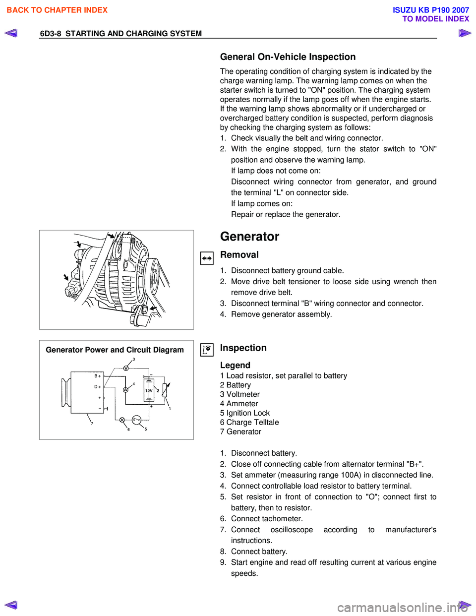
Generator Power and Circuit Diagram
Inspection
Legend
1 Load resistor, set parallel to battery
2 Battery
3 Voltmeter
4 Ammeter
5 Ignition Lock
6 Charge Telltale
7 Generator
1. Disconnect battery.
2. Close off connecting cable from alternator terminal "B+".
3. Set ammeter (measuring range 100A) in disconnected line.
4. Connect controllable load resistor to battery terminal.
5. Set resistor in front of connection to "O"; connect first to battery, then to resistor.
6. Connect tachometer.
7. Connect oscilloscope according to manufacturer's instructions.
8. Connect battery.
9. Start engine and read off resulting current at various engine speeds.
BACK TO CHAPTER INDEX
TO MODEL INDEX
ISUZU KB P190 2007