2007 ISUZU KB P190 display
[x] Cancel search: displayPage 3497 of 6020
Engine Management – V6 – Diagnostics Page 6C1-2–219
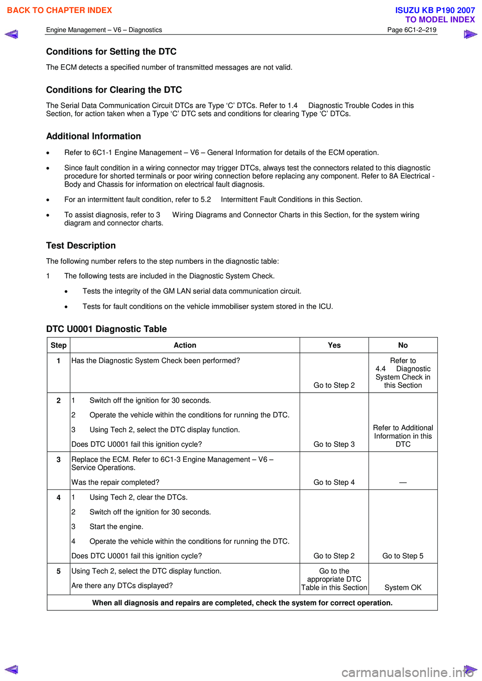
Conditions for Setting the DTC
The ECM detects a specified number of transmitted messages are not valid.
Conditions for Clearing the DTC
The Serial Data Communication Circuit DTCs are Type ‘C’ DTCs. Refer to 1.4 Diagnostic Trouble Codes in this
Section, for action taken when a Type ‘C’ DTC sets and conditions for clearing Type ‘C’ DTCs.
Additional Information
• Refer to 6C1-1 Engine Management – V6 – General Information for details of the ECM operation.
• Since fault condition in a wiring connector may trigger DTCs, always test the connectors related to this diagnostic
procedure for shorted terminals or poor wiring connection before replacing any component. Refer to 8A Electrical -
Body and Chassis for information on electrical fault diagnosis.
• For an intermittent fault condition, refer to 5.2 Intermittent Fault Conditions in this Section.
• To assist diagnosis, refer to 3 W iring Diagrams and Connector Charts in this Section, for the system wiring
diagram and connector charts.
Test Description
The following number refers to the step numbers in the diagnostic table:
1 The following tests are included in the Diagnostic System Check.
• Tests the integrity of the GM LAN serial data communication circuit.
• Tests for fault conditions on the vehicle immobiliser system stored in the ICU.
DTC U0001 Diagnostic Table
Step Action Yes No
1 Has the Diagnostic System Check been performed?
Go to Step 2 Refer to
4.4 Diagnostic
System Check in this Section
2 1 Switch off the ignition for 30 seconds.
2 Operate the vehicle within the conditions for running the DTC.
3 Using Tech 2, select the DTC display function.
Does DTC U0001 fail this ignition cycle? Go to Step 3 Refer to Additional
Information in this DTC
3 Replace the ECM. Refer to 6C1-3 Engine Management – V6 –
Service Operations.
W as the repair completed? Go to Step 4 —
4 1 Using Tech 2, clear the DTCs.
2 Switch off the ignition for 30 seconds.
3 Start the engine.
4 Operate the vehicle within the conditions for running the DTC.
Does DTC U0001 fail this ignition cycle? Go to Step 2 Go to Step 5
5 Using Tech 2, select the DTC display function.
Are there any DTCs displayed? Go to the
appropriate DTC
Table in this Section System OK
When all diagnosis and repairs are completed, check the system for correct operation.
BACK TO CHAPTER INDEX
TO MODEL INDEX
ISUZU KB P190 2007
Page 3499 of 6020
Engine Management – V6 – Diagnostics Page 6C1-2–221
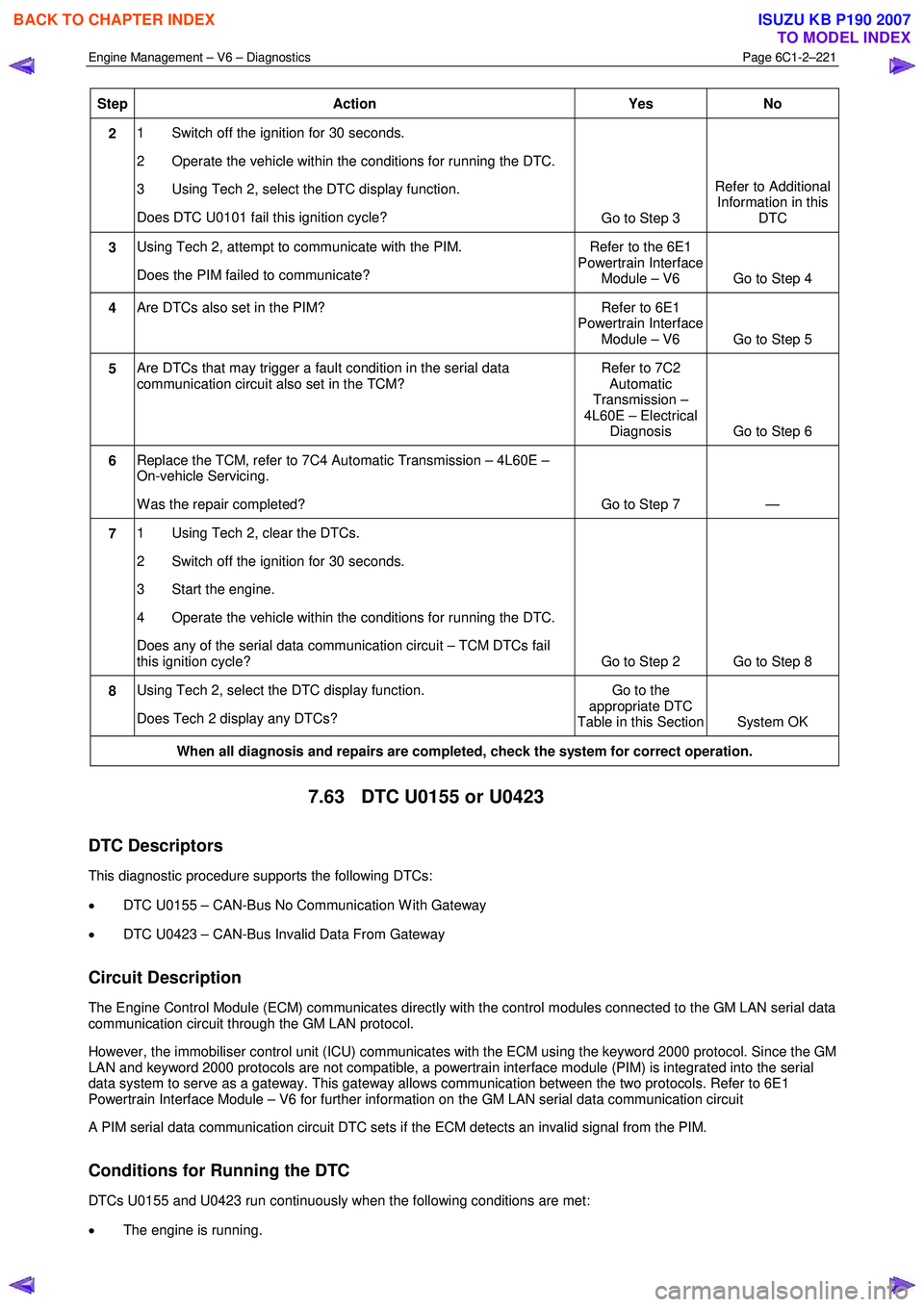
Step Action Yes No
2 1 Switch off the ignition for 30 seconds.
2 Operate the vehicle within the conditions for running the DTC.
3 Using Tech 2, select the DTC display function.
Does DTC U0101 fail this ignition cycle? Go to Step 3 Refer to Additional
Information in this DTC
3 Using Tech 2, attempt to communicate with the PIM.
Does the PIM failed to communicate? Refer to the 6E1
Powertrain Interface Module – V6 Go to Step 4
4 Are DTCs also set in the PIM? Refer to 6E1
Powertrain Interface Module – V6 Go to Step 5
5 Are DTCs that may trigger a fault condition in the serial data
communication circuit also set in the TCM? Refer to 7C2
Automatic
Transmission –
4L60E – Electrical Diagnosis Go to Step 6
6 Replace the TCM, refer to 7C4 Automatic Transmission – 4L60E –
On-vehicle Servicing.
W as the repair completed? Go to Step 7 —
7 1 Using Tech 2, clear the DTCs.
2 Switch off the ignition for 30 seconds.
3 Start the engine.
4 Operate the vehicle within the conditions for running the DTC.
Does any of the serial data communication circuit – TCM DTCs fail
this ignition cycle? Go to Step 2 Go to Step 8
8 Using Tech 2, select the DTC display function.
Does Tech 2 display any DTCs? Go to the
appropriate DTC
Table in this Section System OK
When all diagnosis and repairs are completed, check the system for correct operation.
7.63 DTC U0155 or U0423
DTC Descriptors
This diagnostic procedure supports the following DTCs:
• DTC U0155 – CAN-Bus No Communication W ith Gateway
• DTC U0423 – CAN-Bus Invalid Data From Gateway
Circuit Description
The Engine Control Module (ECM) communicates directly with the control modules connected to the GM LAN serial data
communication circuit through the GM LAN protocol.
However, the immobiliser control unit (ICU) communicates with the ECM using the keyword 2000 protocol. Since the GM
LAN and keyword 2000 protocols are not compatible, a powertrain interface module (PIM) is integrated into the serial
data system to serve as a gateway. This gateway allows communication between the two protocols. Refer to 6E1
Powertrain Interface Module – V6 for further information on the GM LAN serial data communication circuit
A PIM serial data communication circuit DTC sets if the ECM detects an invalid signal from the PIM.
Conditions for Running the DTC
DTCs U0155 and U0423 run continuously when the following conditions are met:
• The engine is running.
BACK TO CHAPTER INDEX
TO MODEL INDEX
ISUZU KB P190 2007
Page 3500 of 6020
Engine Management – V6 – Diagnostics Page 6C1-2–222
• The ignition voltage is 10.0 – 16.0 V.
Conditions for Setting the DTC
The ECM did not receive a valid signal from the PIM within the specified time frame.
Conditions for Clearing the DTC
The PIM serial data communication circuit DTCs are Type C DTCs. Refer to 1.4 Diagnostic Trouble Codes in this
Section, for action taken when a Type C DTC sets and conditions for clearing Type C DTCs.
Additional Information
• Refer to 6C1-1 Engine Management – V6 – General Information for details of the ECM operation.
• Since fault condition in a wiring connector may trigger DTCs, always test the connectors related to this diagnostic
procedure for shorted terminals or poor wiring connection before replacing any component. Refer to 8A Electrical -
Body and Chassis for information on electrical fault diagnosis.
• For an intermittent fault condition, refer to 5.2 Intermittent Fault Conditions in this Section.
• To assist diagnosis, refer to 3 W iring Diagrams and Connector Charts in this Section, for the system wiring
diagram and connector charts.
Test Description
The following number refers to the step numbers in the diagnostic table:
1 The following tests are included in the Diagnostic System Check.
• Tests the integrity of the GM LAN serial data communication circuit.
• Tests for fault conditions on the vehicle immobiliser system stored in the ICU.
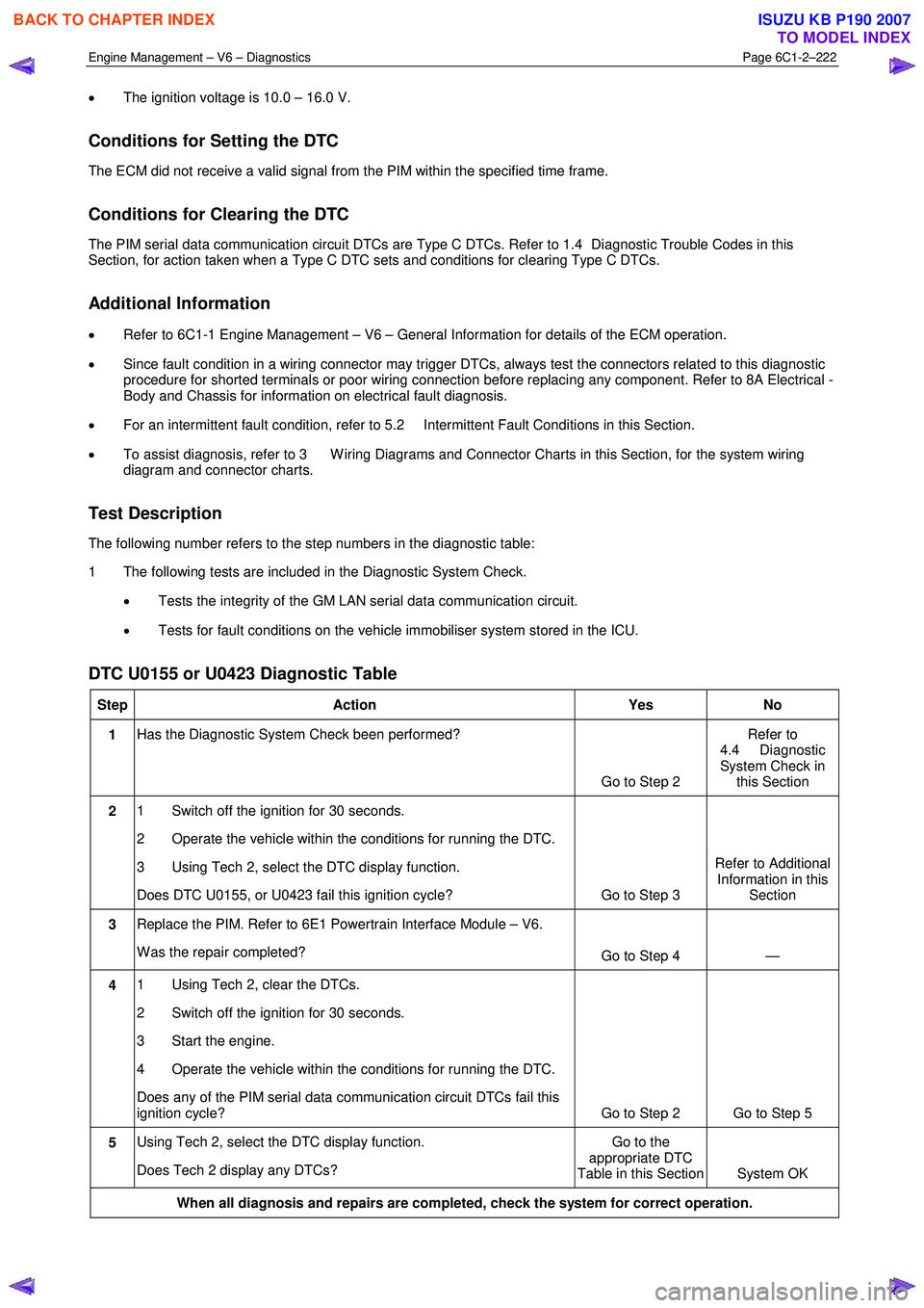
DTC U0155 or U0423 Diagnostic Table
Step Action Yes No
1 Has the Diagnostic System Check been performed?
Go to Step 2 Refer to
4.4 Diagnostic
System Check in this Section
2 1 Switch off the ignition for 30 seconds.
2 Operate the vehicle within the conditions for running the DTC.
3 Using Tech 2, select the DTC display function.
Does DTC U0155, or U0423 fail this ignition cycle? Go to Step 3 Refer to Additional
Information in this Section
3 Replace the PIM. Refer to 6E1 Powertrain Interface Module – V6.
W as the repair completed? Go to Step 4 —
4 1 Using Tech 2, clear the DTCs.
2 Switch off the ignition for 30 seconds.
3 Start the engine.
4 Operate the vehicle within the conditions for running the DTC.
Does any of the PIM serial data communication circuit DTCs fail this
ignition cycle? Go to Step 2 Go to Step 5
5 Using Tech 2, select the DTC display function.
Does Tech 2 display any DTCs? Go to the
appropriate DTC
Table in this Section System OK
When all diagnosis and repairs are completed, check the system for correct operation.
BACK TO CHAPTER INDEX
TO MODEL INDEX
ISUZU KB P190 2007
Page 3501 of 6020
Engine Management – V6 – Diagnostics Page 6C1-2–223
8 HFV6 Engine – Tech 2 Functions
8.1 Introduction
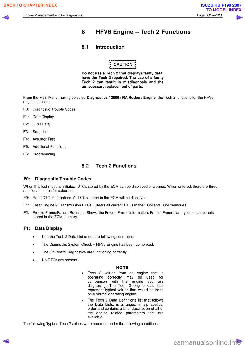
Do not use a Tech 2 that displays faulty data;
have the Tech 2 repaired. The use of a faulty
Tech 2 can result in misdiagnosis and the
unnecessary replacement of parts.
From the Main Menu, having selected Diagnostics / 2006 / RA Rodeo / Engine , the Tech 2 functions for the HFV6
engine, include:
F0: Diagnostic Trouble Codes
F1: Data Display
F2: OBD Data
F3: Snapshot
F4: Actuator Test
F5: Additional Functions
F6: Programming
8.2 Tech 2 Functions
F0: Diagnostic Trouble Codes
W hen this test mode is initiated, DTCs stored by the ECM can be displayed or cleared. W hen entered, there are three
additional modes for selection:
F0: Read DTC Information: All DTCs stored in the ECM will be displayed.
F1: Clear Engine & Transmission DTCs: Clears all current DTCs in the ECM and TCM memories.
F2: Freeze Frame/Failure Records: Shows the Freeze Frame information. Freeze Frames are types of snapshots stored in the ECM memory.
F1: Data Display
• Use the Tech 2 Data List under the following conditions:
• The Diagnostic System Check – HFV6 Engine has been completed.
• The On-Board Diagnostics are functioning correctly.
• No DTCs are present.
NOTE
• Tech 2 values from an engine that is
operating correctly may be used for
comparison with the engine you are
diagnosing. The Tech 2 engine data lists
represent typical values that would be seen
on a normal operating engine.
• The Tech 2 Data Definitions list that follows
the Data Lists, is arranged in alphabetical
order and contains a brief description of all of
the engine related parameters that are
available.
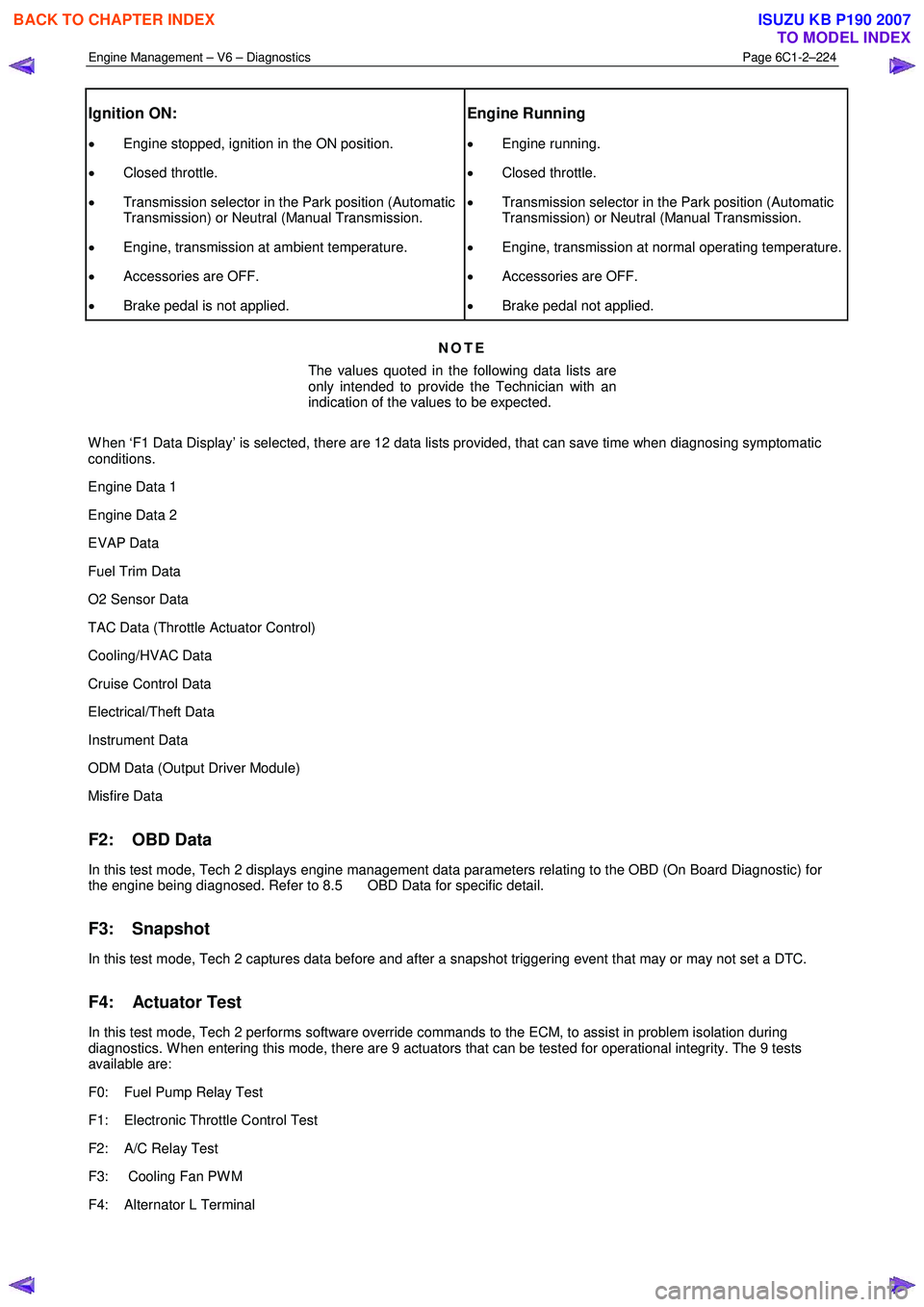
The following ‘typical’ Tech 2 values were recorded under the following conditions:
BACK TO CHAPTER INDEX
TO MODEL INDEX
ISUZU KB P190 2007
Page 3502 of 6020
Engine Management – V6 – Diagnostics Page 6C1-2–224
Ignition ON:
• Engine stopped, ignition in the ON position.
• Closed throttle.
• Transmission selector in the Park position (Automatic
Transmission) or Neutral (Manual Transmission.
• Engine, transmission at ambient temperature.
• Accessories are OFF.
• Brake pedal is not applied.
Engine Running
• Engine running.
• Closed throttle.
• Transmission selector in the Park position (Automatic
Transmission) or Neutral (Manual Transmission.
• Engine, transmission at normal operating temperature.
• Accessories are OFF.
• Brake pedal not applied.
NOTE
The values quoted in the following data lists are
only intended to provide the Technician with an
indication of the values to be expected.
W hen ‘F1 Data Display’ is selected, there are 12 data lists provided, that can save time when diagnosing symptomatic
conditions.
Engine Data 1
Engine Data 2
EVAP Data
Fuel Trim Data
O2 Sensor Data
TAC Data (Throttle Actuator Control)
Cooling/HVAC Data
Cruise Control Data
Electrical/Theft Data
Instrument Data
ODM Data (Output Driver Module)
Misfire Data
F2: OBD Data
In this test mode, Tech 2 displays engine management data parameters relating to the OBD (On Board Diagnostic) for
the engine being diagnosed. Refer to 8.5 OBD Data for specific detail.
F3: Snapshot
In this test mode, Tech 2 captures data before and after a snapshot triggering event that may or may not set a DTC.
F4: Actuator Test
In this test mode, Tech 2 performs software override commands to the ECM, to assist in problem isolation during
diagnostics. W hen entering this mode, there are 9 actuators that can be tested for operational integrity. The 9 tests
available are:
F0: Fuel Pump Relay Test
F1: Electronic Throttle Control Test
F2: A/C Relay Test
F3: Cooling Fan PW M
F4: Alternator L Terminal
BACK TO CHAPTER INDEX
TO MODEL INDEX
ISUZU KB P190 2007
Page 3503 of 6020
Engine Management – V6 – Diagnostics Page 6C1-2–225
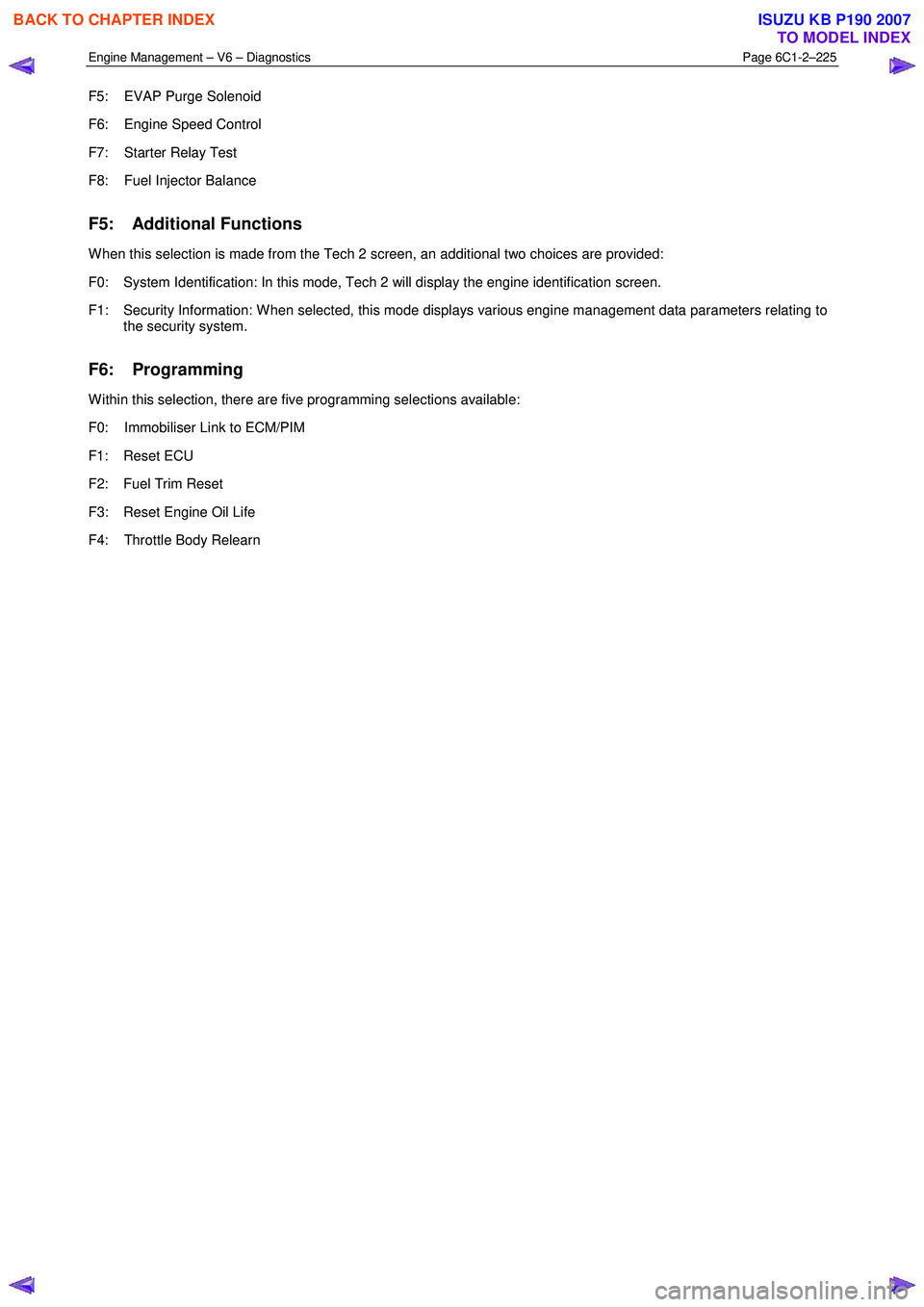
F5: EVAP Purge Solenoid
F6: Engine Speed Control
F7: Starter Relay Test
F8: Fuel Injector Balance
F5: Additional Functions
W hen this selection is made from the Tech 2 screen, an additional two choices are provided:
F0: System Identification: In this mode, Tech 2 will display the engine identification screen.
F1: Security Information: W hen selected, this mode displays various engine management data parameters relating to the security system.
F6: Programming
W ithin this selection, there are five programming selections available:
F0: Immobiliser Link to ECM/PIM
F1: Reset ECU
F2: Fuel Trim Reset
F3: Reset Engine Oil Life
F4: Throttle Body Relearn
BACK TO CHAPTER INDEX
TO MODEL INDEX
ISUZU KB P190 2007
Page 3504 of 6020
Engine Management – V6 – Diagnostics Page 6C1-2–226
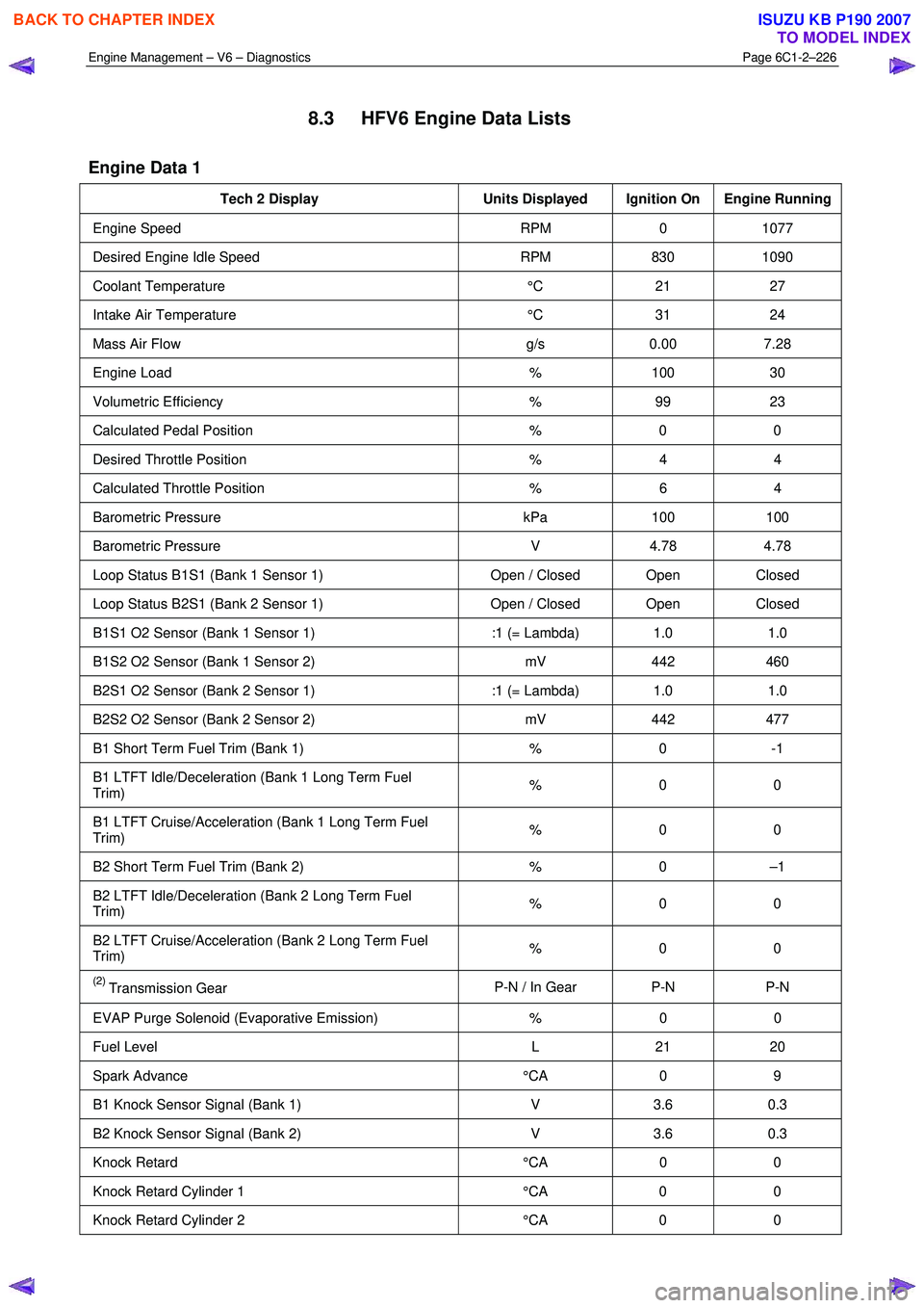
8.3 HFV6 Engine Data Lists
Engine Data 1
Tech 2 Display Units Displayed Ignition On Engine Running
Engine Speed RPM 0 1077
Desired Engine Idle Speed RPM 830 1090
Coolant Temperature °C 21 27
Intake Air Temperature °C 31 24
Mass Air Flow g/s 0.00 7.28
Engine Load % 100 30
Volumetric Efficiency % 99 23
Calculated Pedal Position % 0 0
Desired Throttle Position % 4 4
Calculated Throttle Position % 6 4
Barometric Pressure kPa 100 100
Barometric Pressure V 4.78 4.78
Loop Status B1S1 (Bank 1 Sensor 1) Open / Closed Open Closed
Loop Status B2S1 (Bank 2 Sensor 1) Open / Closed Open Closed
B1S1 O2 Sensor (Bank 1 Sensor 1) :1 (= Lambda) 1.0 1.0
B1S2 O2 Sensor (Bank 1 Sensor 2) mV 442 460
B2S1 O2 Sensor (Bank 2 Sensor 1) :1 (= Lambda) 1.0 1.0
B2S2 O2 Sensor (Bank 2 Sensor 2) mV 442 477
B1 Short Term Fuel Trim (Bank 1) % 0 -1
B1 LTFT Idle/Deceleration (Bank 1 Long Term Fuel
Trim) % 0 0
B1 LTFT Cruise/Acceleration (Bank 1 Long Term Fuel
Trim) % 0 0
B2 Short Term Fuel Trim (Bank 2)
% 0 –1
B2 LTFT Idle/Deceleration (Bank 2 Long Term Fuel
Trim) % 0 0
B2 LTFT Cruise/Acceleration (Bank 2 Long Term Fuel
Trim) % 0 0
(2) Transmission Gear
P-N / In Gear P-N P-N
EVAP Purge Solenoid (Evaporative Emission)
% 0 0
Fuel Level L 21 20
Spark Advance °CA 0 9
B1 Knock Sensor Signal (Bank 1) V 3.6 0.3
B2 Knock Sensor Signal (Bank 2) V 3.6 0.3
Knock Retard °CA 0 0
Knock Retard Cylinder 1 °CA 0 0
Knock Retard Cylinder 2 °CA 0 0
BACK TO CHAPTER INDEX
TO MODEL INDEX
ISUZU KB P190 2007
Page 3505 of 6020
Engine Management – V6 – Diagnostics Page 6C1-2–227
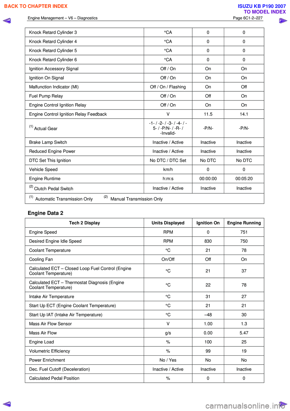
Knock Retard Cylinder 3 °CA 0 0
Knock Retard Cylinder 4 °CA 0 0
Knock Retard Cylinder 5 °CA 0 0
Knock Retard Cylinder 6 °CA 0 0
Ignition Accessory Signal Off / On On On
Ignition On Signal Off / On On On
Malfunction Indicator (MI) Off / On / Flashing On Off
Fuel Pump Relay Off / On Off On
Engine Control Ignition Relay Off / On On On
Engine Control Ignition Relay Feedback V 11.5 14.1
(1) Actual Gear -1- / -2- / -3- / -4- / -
5- / -P/N- / -R- / -Invalid- -P/N- -P/N-
Brake Lamp Switch
Inactive / Active Inactive Inactive
Reduced Engine Power Inactive / Active Inactive Inactive
DTC Set This Ignition No DTC / DTC Set No DTC No DTC
Vehicle Speed km/h 0 0
Engine Runtime h:m:s 00:00:00 00:05:20
(2) Clutch Pedal Switch Inactive / Active Inactive Inactive
(1) Automatic Transmission Only (2) Manual Transmission Only
Engine Data 2
Tech 2 Display
Units Displayed Ignition On Engine Running
Engine Speed RPM 0 751
Desired Engine Idle Speed RPM 830 750
Coolant Temperature °C 21 78
Cooling Fan On/Off Off On
Calculated ECT – Closed Loop Fuel Control (Engine
Coolant Temperature) °C 21 37
Calculated ECT – Thermostat Diagnosis (Engine
Coolant Temperature) °C 22 78
Intake Air Temperature
°C 31 27
Start Up ECT (Engine Coolant Temperature) °C 21 21
Start Up IAT (Intake Air Temperature) °C –48 30
Mass Air Flow Sensor V 1.00 1.3
Mass Air Flow g/s 0.00 5.47
Engine Load % 100 25
Volumetric Efficiency % 99 19
Power Enrichment No / Yes No No
Dec. Fuel Cutoff (Deceleration) Inactive / Active Inactive Inactive
Calculated Pedal Position % 0 0
BACK TO CHAPTER INDEX
TO MODEL INDEX
ISUZU KB P190 2007