Page 1548 of 6020
FUEL SYSTEM (4JK1/4JJ1) 6C-7
g. Check that the warning lamp in the meter is off.
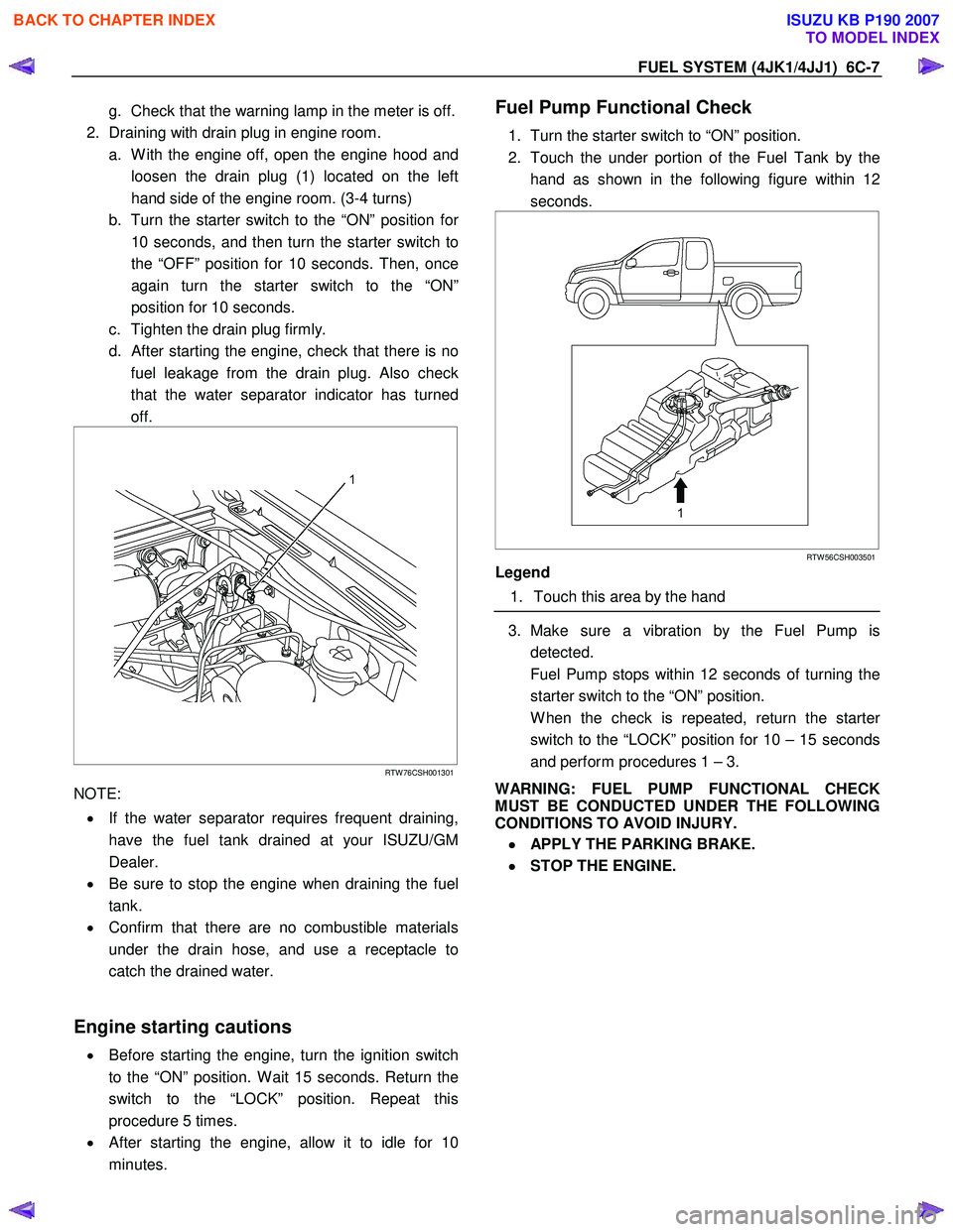
2. Draining with drain plug in engine room. a. W ith the engine off, open the engine hood and loosen the drain plug (1) located on the left
hand side of the engine room. (3-4 turns)
b. Turn the starter switch to the “ON” position fo
r
10 seconds, and then turn the starter switch to
the “OFF” position for 10 seconds. Then, once
again turn the starter switch to the “ON”
position for 10 seconds.
c. Tighten the drain plug firmly.
d.
After starting the engine, check that there is no
fuel leakage from the drain plug. Also check
that the water separator indicator has turned
off.
RTW 76CSH001301
NOTE:
• If the water separator requires frequent draining,
have the fuel tank drained at your ISUZU/GM
Dealer.
• Be sure to stop the engine when draining the fuel
tank.
• Confirm that there are no combustible materials
under the drain hose, and use a receptacle to
catch the drained water.
Engine starting cautions
• Before starting the engine, turn the ignition switch
to the “ON” position. W ait 15 seconds. Return the
switch to the “LOCK” position. Repeat this
procedure 5 times.
• After starting the engine, allow it to idle for 10
minutes.
Fuel Pump Functional Check
1. Turn the starter switch to “ON” position.
2. Touch the under portion of the Fuel Tank by the hand as shown in the following figure within 12
seconds.
RTW 56CSH003501
Legend
1. Touch this area by the hand
3. Make sure a vibration by the Fuel Pump is
detected.
Fuel Pump stops within 12 seconds of turning the starter switch to the “ON” position.
W hen the check is repeated, return the starte
r
switch to the “LOCK” position for 10 – 15 seconds
and perform procedures 1 – 3.
WARNING: FUEL PUMP FUNCTIONAL CHECK
MUST BE CONDUCTED UNDER THE FOLLOWING
CONDITIONS TO AVOID INJURY.
•
••
•
APPLY THE PARKING BRAKE.
•
••
•
STOP THE ENGINE.
BACK TO CHAPTER INDEX
TO MODEL INDEX
ISUZU KB P190 2007
Page 1551 of 6020
6C-10 FUEL SYSTEM (4JK1/4JJ1)
Fuel System Check
Description
Conforms to a fuel leak. Engine acceleration raises fuel
pressure and which increases the leak.
Leak could be in the following pipes and locations.
• Between injectors and fuel rail.
• Between fuel rail and fuel supply pump.
• Between fuel supply pump and fuel filter.
• Between fuel filter and fuel tank.
• Between pressure limiter and fuel cooler.
• Between fuel cooler and fuel tank.
• Between injector over flow and leak off pipe.
Diagnostic Aids
Check the following items.
• Air in the fuel line
• Clogged fuel filter
• Fuel pipe malfunction (Crushing, breakage,
clogging, disconnection, etc.)
• Fuel cooler malfunction (Crushing, breakage,
clogging, disconnection, etc.)
• Fuel tank malfunction
• Injector malfunction
• Fuel supply pump malfunction
• Pressure limiter malfunction
An intermittent may be caused by a poor connection,
rubbed-through wire insulation or a wire broken inside
the insulation. Check for poor connections or a
damaged harness.
Inspect the ECM harness and connector for imprope
r
mating, broken locks, improperly formed or damaged
terminals, poor terminal-to-wire connection, and
damaged harness.
ECU may set a DTC, if there is adequate air in fuel line.
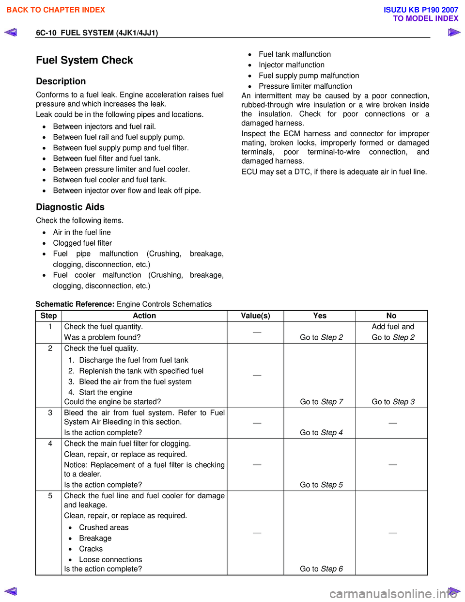
Schematic Reference: Engine Controls Schematics
Step Action Value(s) Yes No
1 Check the fuel quantity. W as a problem found?
Go to Step 2 Add fuel and
Go to Step 2
2 Check the fuel quality.
1. Discharge the fuel from fuel tank
2. Replenish the tank with specified fuel
3. Bleed the air from the fuel system
4. Start the engine
Could the engine be started?
Go to Step 7 Go to Step 3
3 Bleed the air from fuel system. Refer to Fuel
System Air Bleeding in this section.
Is the action complete?
Go to Step 4
4 Check the main fuel filter for clogging.
Clean, repair, or replace as required.
Notice: Replacement of a fuel filter is checking
to a dealer.
Is the action complete?
Go to Step 5
5 Check the fuel line and fuel cooler for damage
and leakage.
Clean, repair, or replace as required.
• Crushed areas
• Breakage
• Cracks
• Loose connections
Is the action complete?
Go to Step 6
BACK TO CHAPTER INDEX
TO MODEL INDEX
ISUZU KB P190 2007
Page 1554 of 6020
FUEL SYSTEM (4JK1/4JJ1) 6C-13
Fuel Filter Element
Removal
1. Detach the drain hose on the lower part of the fuel
filter or the drain plug, loosen the air bleed plug,
and drain the fuel from the fuel filter.
2. Detach the water-in-fuel switch harness.
3. Turn the element case counterclockwise to detach, and remove the filter element.
4. Replace the O-ring and confirm the snap-fit position, and fit a new filter element inside the
element case.
NOTE
It is strongly advisable to use the ISUZU/GM genuine
fuel filter for replacement.
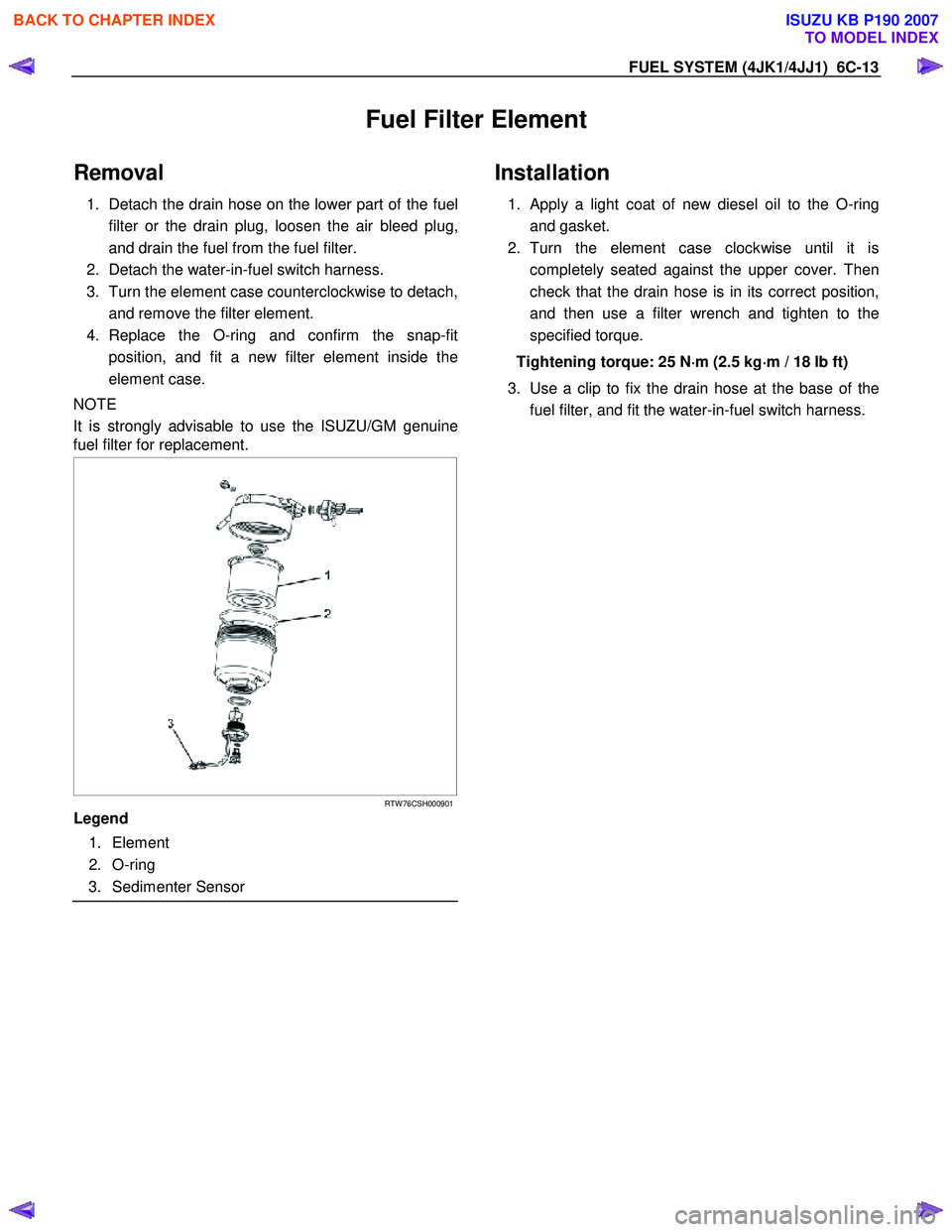
RTW 76CSH000901
Legend
1. Element
2. O-ring
3. Sedimenter Sensor
Installation
1. Apply a light coat of new diesel oil to the O-ring
and gasket.
2. Turn the element case clockwise until it is completely seated against the upper cover. Then
check that the drain hose is in its correct position,
and then use a filter wrench and tighten to the
specified torque.
Tightening torque: 25 N ⋅
⋅⋅
⋅
m (2.5 kg ⋅
⋅⋅
⋅
m / 18 lb ft)
3. Use a clip to fix the drain hose at the base of the fuel filter, and fit the water-in-fuel switch harness.
BACK TO CHAPTER INDEX
TO MODEL INDEX
ISUZU KB P190 2007
Page 1576 of 6020
FUEL SYSTEM (4JK1/4JJ1) 6C-35
9. Install the timing chain tensioner.
Tighten the nut to the specified torque.
Tightening torque: 10 N ⋅
⋅⋅
⋅
m (1.0 kg ⋅
⋅⋅
⋅
m/ 87 lb in)
RTW 56CSH001701
Legend
1. Timing Chain Tensioner
2. Gasket
3. Nut
10. Unlock the tensioner hook.
• Press the place of the arrow in the figure.
• The hook is opened. The plunger pushes the
tension lever.
RTW 56ASH020401
11. Tighten the fuel supply pump shaft nut.
Tighten the nut (1) to the specified torque.
Tightening torque: 130 N ⋅
⋅⋅
⋅
m (13.3 kg ⋅
⋅⋅
⋅
m / 96 lb ft)
RTW 56CSH001601
12. Tighten the timing chain tension lever pivot bolt to
the specified torque.
Tightening torque: 27 N ⋅
⋅⋅
⋅
m (2.8 kg ⋅
⋅⋅
⋅
m / 20 lb ft)
13. Turn the crank pulley two rotations (720°CA).
14. Check mark (1) on intake camshaft and exhaust camshaft to mark of camshaft bearing cap.
RTW 56ASH006901
BACK TO CHAPTER INDEX
TO MODEL INDEX
ISUZU KB P190 2007
Page 1583 of 6020
6C-42 FUEL SYSTEM (4JK1/4JJ1)
Fuel Gauge Unit
Fuel Gauge Unit and Associated Parts
RTW 56CLF001001
Legend 1. Fuel Tube/Quick Connector
2. Fuel Feed Port
3. Retainer Ring (Fuel Gauge Unit Lock)
4. Connector; Fuel Gauge Unit 5. Fuel Return Port
6. Fuel Gauge Unit and Sender Assembly
7. Seal; Fuel Gauge Unit
8. Fuel Tank Assembly
BACK TO CHAPTER INDEX
TO MODEL INDEX
ISUZU KB P190 2007
Page 1584 of 6020
FUEL SYSTEM (4JK1/4JJ1) 6C-43
Removal
Note: W hen repairs to the fuel system have been
completed, start the engine and check the fuel system
for loose connections or leakage. For the fuel system
diagnosis, see Section "Drivability and Emission".
1. Remove the fuel tank assembly (8). Refer to "Fuel Tank Removal" in this section.
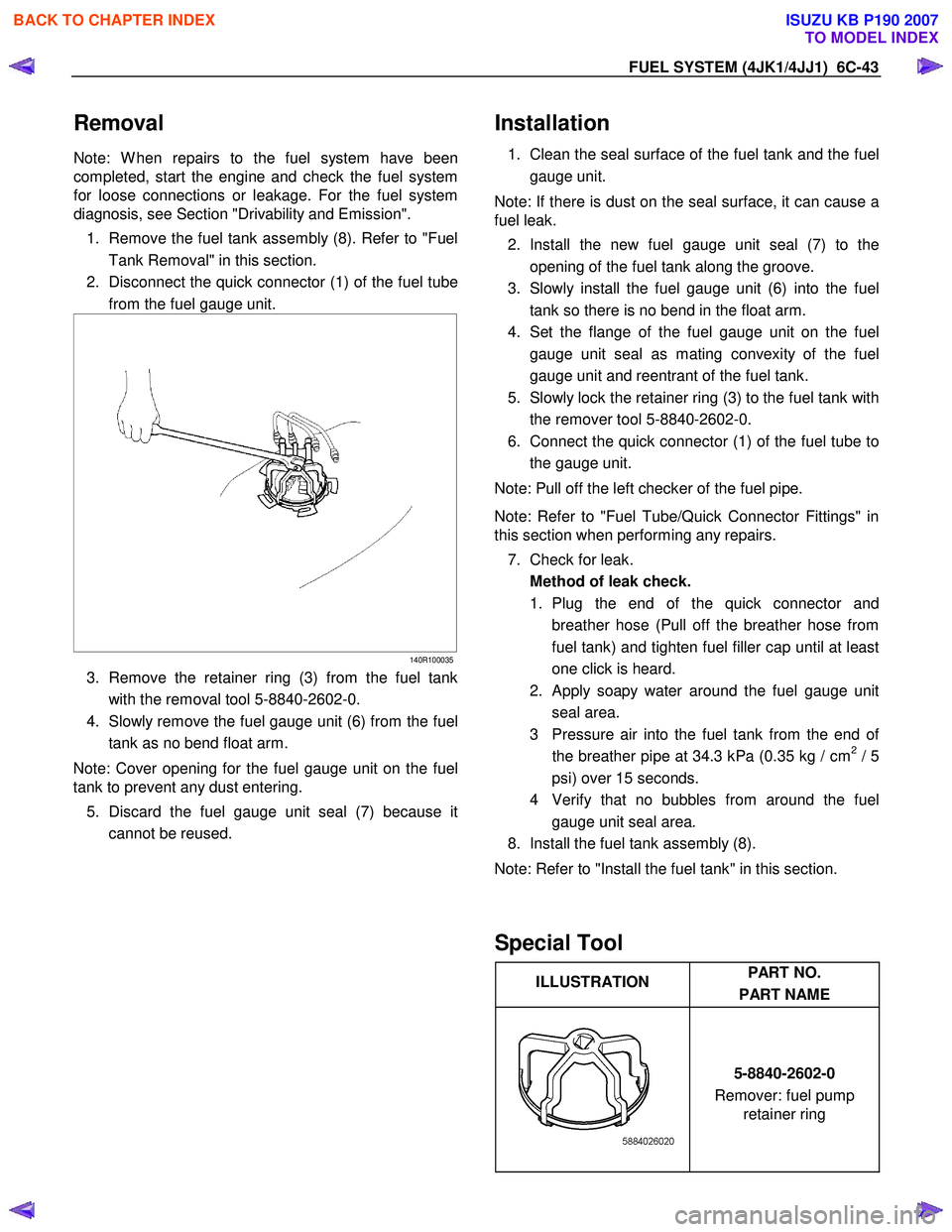
2. Disconnect the quick connector (1) of the fuel tube from the fuel gauge unit.
140R100035
3. Remove the retainer ring (3) from the fuel tank
with the removal tool 5-8840-2602-0.
4. Slowly remove the fuel gauge unit (6) from the fuel tank as no bend float arm.
Note: Cover opening for the fuel gauge unit on the fuel
tank to prevent any dust entering.
5. Discard the fuel gauge unit seal (7) because it cannot be reused.
Installation
1. Clean the seal surface of the fuel tank and the fuel
gauge unit.
Note: If there is dust on the seal surface, it can cause a
fuel leak.
2. Install the new fuel gauge unit seal (7) to the opening of the fuel tank along the groove.
3. Slowly install the fuel gauge unit (6) into the fuel tank so there is no bend in the float arm.
4. Set the flange of the fuel gauge unit on the fuel gauge unit seal as mating convexity of the fuel
gauge unit and reentrant of the fuel tank.
5. Slowly lock the retainer ring (3) to the fuel tank with the remover tool 5-8840-2602-0.
6. Connect the quick connector (1) of the fuel tube to the gauge unit.
Note: Pull off the left checker of the fuel pipe.
Note: Refer to "Fuel Tube/Quick Connector Fittings" in
this section when performing any repairs.
7. Check for leak. Method of leak check.
1. Plug the end of the quick connector and breather hose (Pull off the breather hose from
fuel tank) and tighten fuel filler cap until at least
one click is heard.
2. Apply soapy water around the fuel gauge unit seal area.
3 Pressure air into the fuel tank from the end o
f
the breather pipe at 34.3 kPa (0.35 kg / cm2 / 5
psi) over 15 seconds.
4 Verify that no bubbles from around the fuel gauge unit seal area.
8. Install the fuel tank assembly (8).
Note: Refer to "Install the fuel tank" in this section.
Special Tool
ILLUSTRATION PART NO.
PART NAME
5-8840-2602-0
Remover: fuel pump retainer ring
BACK TO CHAPTER INDEX
TO MODEL INDEX
ISUZU KB P190 2007
Page 1586 of 6020
FUEL SYSTEM (4JK1/4JJ1) 6C-45
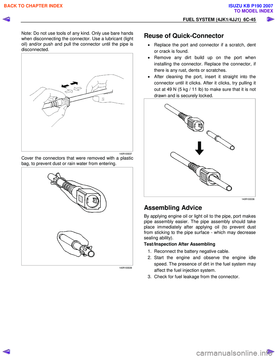
Note: Do not use tools of any kind. Only use bare hands
when disconnecting the connector. Use a lubricant (light
oil) and/or push and pull the connector until the pipe is
disconnected.
140R100037
Cover the connectors that were removed with a plastic
bag, to prevent dust or rain water from entering.
140R100028
Reuse of Quick-Connector
•
Replace the port and connector if a scratch, dent
or crack is found.
• Remove any dirt build up on the port when
installing the connector. Replace the connector, i
f
there is any rust, dents or scratches.
• After cleaning the port, insert it straight into the
connector until it clicks. After it clicks, try pulling it
out at 49 N (5 kg / 11 lb) to make sure that it is not
drawn and is securely locked.
140R100036
Assembling Advice
By applying engine oil or light oil to the pipe, port makes
pipe assembly easier. The pipe assembly should take
place immediately after applying oil (to prevent dust
from sticking to the pipe surface - which may decrease
sealing ability).
Test/Inspection After Assembling
1. Reconnect the battery negative cable.
2. Start the engine and observe the engine idle speed. The presence of dirt in the fuel system ma
y
affect the fuel injection system.
3. Check for fuel leakage from the connector.
BACK TO CHAPTER INDEX
TO MODEL INDEX
ISUZU KB P190 2007
Page 1596 of 6020
6D-8 ENGINE ELECTRICAL (4JK1/4JJ1)
Specifications
Battery power Volts 12
Generator output Amperes 90
Rotational direction (Viewed from pulley) Clockwise
Rated speed 5,000
Maximum speed rpm
18,000
BACK TO CHAPTER INDEX
TO MODEL INDEX
ISUZU KB P190 2007