2007 ISUZU KB P190 lock
[x] Cancel search: lockPage 1765 of 6020
6E-148 ENGINE CONTROL SYSTEM (4JK1/4JJ1)
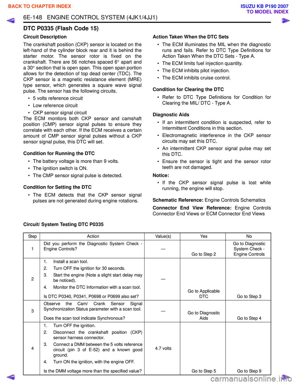
DTC P0335 (Flash Code 15)
Circuit Description
The crankshaft position (CKP) sensor is located on the
left-hand of the cylinder block rear and it is behind the
starter motor. The sensor rotor is fixed on the
crankshaft. There are 56 notches spaced 6 ° apart and
a 30 ° section that is open span. This open span portion
allows for the detection of top dead center (TDC). The
CKP sensor is a magnetic resistance element (MRE)
type sensor, which generates a square wave signal
pulse. The sensor has the following circuits.
• 5 volts reference circuit
• Low reference circuit
• CKP sensor signal circuit
The ECM monitors both CKP sensor and camshaft
position (CMP) sensor signal pulses to ensure they
correlate with each other. If the ECM receives a certain
amount of CMP sensor signal pulses without a CKP
sensor signal pulse, this DTC will set.
Condition for Running the DTC • The battery voltage is more than 9 volts.
• The ignition switch is ON.
• The CMP sensor signal pulse is detected.
Condition for Setting the DTC • The ECM detects that the CKP sensor signal pulses are not generated during engine rotations. Action Taken When the DTC Sets
• The ECM illuminates the MIL when the diagnostic runs and fails. Refer to DTC Type Definitions for
Action Taken When the DTC Sets - Type A.
• The ECM limits fuel injection quantity.
• The ECM inhibits pilot injection.
• The ECM inhibits cruise control.
Condition for Clearing the DTC • Refer to DTC Type Definitions for Condition for Clearing the MIL/ DTC - Type A.
Diagnostic Aids • If an intermittent condition is suspected, refer to Intermittent Conditions in this section.
• Electromagnetic interference in the CKP sensor circuits may set this DTC.
• An intermittent CKP sensor signal pulse may set this DTC.
• Ensure the sensor is tight and the sensor rotor teeth are not damaged.
Notice: • If the CKP sensor signal pulse is lost while running, the engine will stop.
Schematic Reference: Engine Controls Schematics
Connector End View Reference: Engine Controls
Connector End Views or ECM Connector End Views
Circuit/ System Testing DTC P0335
Step Action Value(s)Yes No
1 Did you perform the Diagnostic System Check -
Engine Controls? —
Go to Step 2 Go to Diagnostic
System Check -
Engine Controls
2 1. Install a scan tool.
2. Turn OFF the ignition for 30 seconds.
3. Start the engine (Note a slight start delay may be noticed).
4. Monitor the DTC Information with a scan tool.
Is DTC P0340, P0341, P0698 or P0699 also set? —
Go to Applicable DTC Go to Step 3
3 Observe the Cam/ Crank Sensor Signal
Synchronization Status parameter with a scan tool.
Does the scan tool indicate Synchronous? —
Go to Diagnostic
Aids Go to Step 4
4 1. Turn OFF the ignition.
2. Disconnect the crankshaft position (CKP) sensor harness connector.
3. Connect a DMM between the 5 volts reference circuit (pin 3 of E-52) and a known good
ground.
4. Turn ON the ignition, with the engine OFF.
Is the DMM voltage more than the specified value? 4.7 volts
Go to Step 5 Go to Step 9
BACK TO CHAPTER INDEX
TO MODEL INDEX
ISUZU KB P190 2007
Page 1768 of 6020
ENGINE CONTROL SYSTEM (4JK1/4JJ1) 6E-151
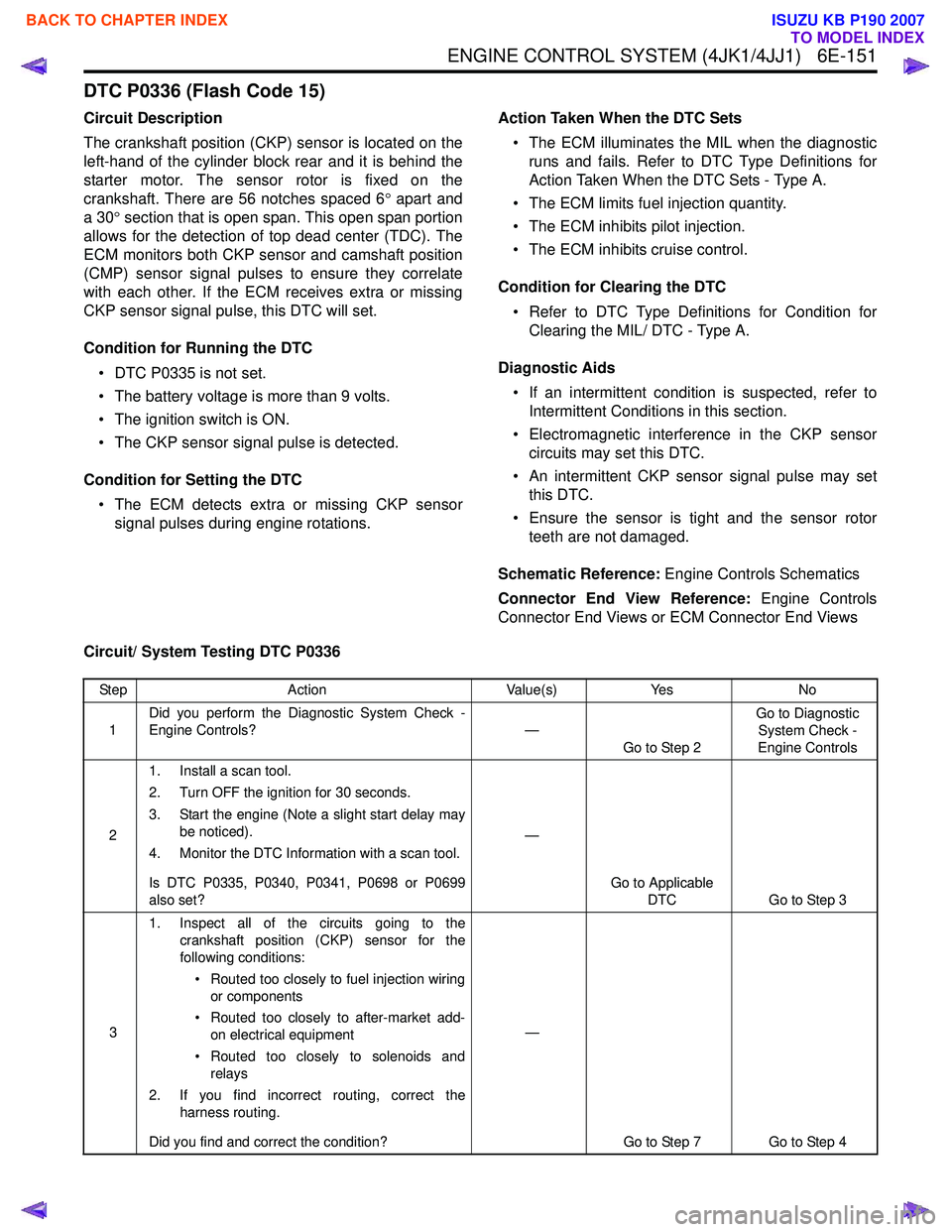
DTC P0336 (Flash Code 15)
Circuit Description
The crankshaft position (CKP) sensor is located on the
left-hand of the cylinder block rear and it is behind the
starter motor. The sensor rotor is fixed on the
crankshaft. There are 56 notches spaced 6 ° apart and
a 30 ° section that is open span. This open span portion
allows for the detection of top dead center (TDC). The
ECM monitors both CKP sensor and camshaft position
(CMP) sensor signal pulses to ensure they correlate
with each other. If the ECM receives extra or missing
CKP sensor signal pulse, this DTC will set.
Condition for Running the DTC • DTC P0335 is not set.
• The battery voltage is more than 9 volts.
• The ignition switch is ON.
• The CKP sensor signal pulse is detected.
Condition for Setting the DTC • The ECM detects extra or missing CKP sensor signal pulses during engine rotations. Action Taken When the DTC Sets
• The ECM illuminates the MIL when the diagnostic runs and fails. Refer to DTC Type Definitions for
Action Taken When the DTC Sets - Type A.
• The ECM limits fuel injection quantity.
• The ECM inhibits pilot injection.
• The ECM inhibits cruise control.
Condition for Clearing the DTC • Refer to DTC Type Definitions for Condition for Clearing the MIL/ DTC - Type A.
Diagnostic Aids • If an intermittent condition is suspected, refer to Intermittent Conditions in this section.
• Electromagnetic interference in the CKP sensor circuits may set this DTC.
• An intermittent CKP sensor signal pulse may set this DTC.
• Ensure the sensor is tight and the sensor rotor teeth are not damaged.
Schematic Reference: Engine Controls Schematics
Connector End View Reference: Engine Controls
Connector End Views or ECM Connector End Views
Circuit/ System Testing DTC P0336
Step Action Value(s)Yes No
1 Did you perform the Diagnostic System Check -
Engine Controls? —
Go to Step 2 Go to Diagnostic
System Check -
Engine Controls
2 1. Install a scan tool.
2. Turn OFF the ignition for 30 seconds.
3. Start the engine (Note a slight start delay may be noticed).
4. Monitor the DTC Information with a scan tool.
Is DTC P0335, P0340, P0341, P0698 or P0699
also set? —
Go to Applicable DTC Go to Step 3
3 1. Inspect all of the circuits going to the
crankshaft position (CKP) sensor for the
following conditions:
• Routed too closely to fuel injection wiring or components
• Routed too closely to after-market add- on electrical equipment
• Routed too closely to solenoids and relays
2. If you find incorrect routing, correct the harness routing.
Did you find and correct the condition? —
Go to Step 7 Go to Step 4
BACK TO CHAPTER INDEX
TO MODEL INDEX
ISUZU KB P190 2007
Page 1779 of 6020
6E-162 ENGINE CONTROL SYSTEM (4JK1/4JJ1)
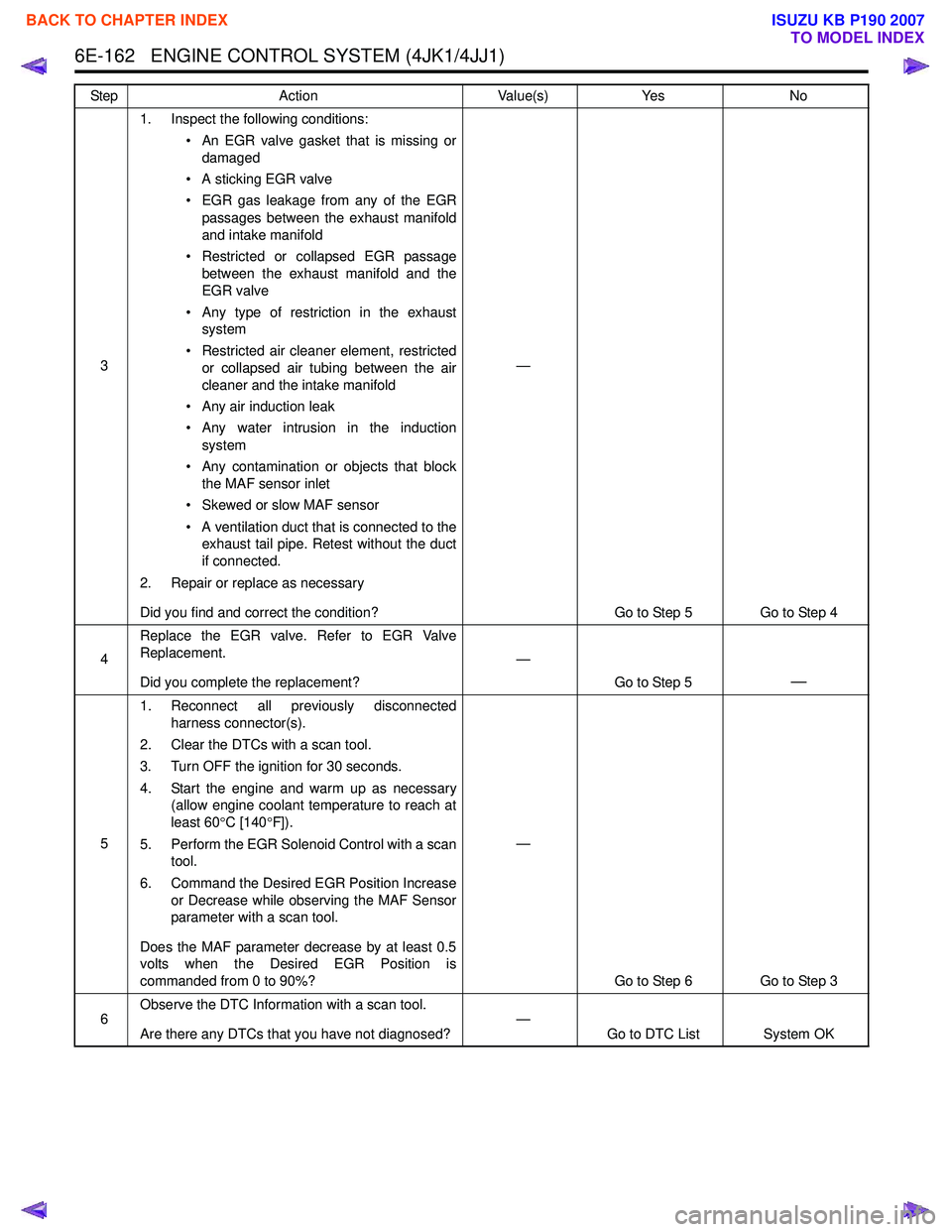
31. Inspect the following conditions:
• An EGR valve gasket that is missing ordamaged
• A sticking EGR valve
• EGR gas leakage from any of the EGR passages between the exhaust manifold
and intake manifold
• Restricted or collapsed EGR passage between the exhaust manifold and the
EGR valve
• Any type of restriction in the exhaust system
• Restricted air cleaner element, restricted or collapsed air tubing between the air
cleaner and the intake manifold
• Any air induction leak
• Any water intrusion in the induction system
• Any contamination or objects that block the MAF sensor inlet
• Skewed or slow MAF sensor
• A ventilation duct that is connected to the exhaust tail pipe. Retest without the duct
if connected.
2. Repair or replace as necessary
Did you find and correct the condition? —
Go to Step 5 Go to Step 4
4 Replace the EGR valve. Refer to EGR Valve
Replacement.
Did you complete the replacement? —
Go to Step 5
—
51. Reconnect all previously disconnected
harness connector(s).
2. Clear the DTCs with a scan tool.
3. Turn OFF the ignition for 30 seconds.
4. Start the engine and warm up as necessary (allow engine coolant temperature to reach at
least 60 °C [140 °F]).
5. Perform the EGR Solenoid Control with a scan tool.
6. Command the Desired EGR Position Increase or Decrease while observing the MAF Sensor
parameter with a scan tool.
Does the MAF parameter decrease by at least 0.5
volts when the Desired EGR Position is
commanded from 0 to 90%? —
Go to Step 6 Go to Step 3
6 Observe the DTC Information with a scan tool.
Are there any DTCs that you have not diagnosed? —
Go to DTC List System OK
Step
Action Value(s)Yes No
BACK TO CHAPTER INDEX
TO MODEL INDEX
ISUZU KB P190 2007
Page 1795 of 6020
6E-178 ENGINE CONTROL SYSTEM (4JK1/4JJ1)
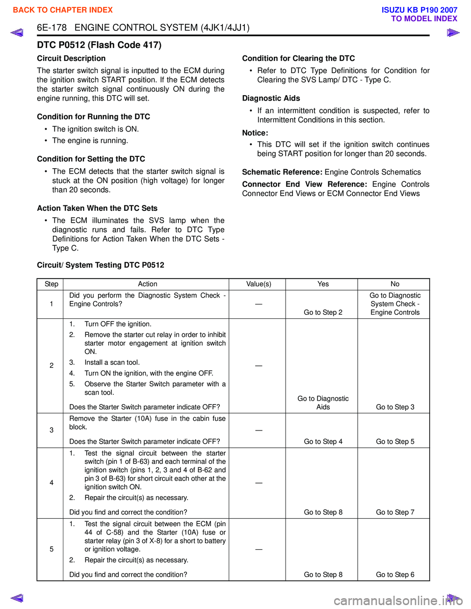
DTC P0512 (Flash Code 417)
Circuit Description
The starter switch signal is inputted to the ECM during
the ignition switch START position. If the ECM detects
the starter switch signal continuously ON during the
engine running, this DTC will set.
Condition for Running the DTC • The ignition switch is ON.
• The engine is running.
Condition for Setting the DTC • The ECM detects that the starter switch signal is stuck at the ON position (high voltage) for longer
than 20 seconds.
Action Taken When the DTC Sets • The ECM illuminates the SVS lamp when the diagnostic runs and fails. Refer to DTC Type
Definitions for Action Taken When the DTC Sets -
Type C. Condition for Clearing the DTC
• Refer to DTC Type Definitions for Condition for Clearing the SVS Lamp/ DTC - Type C.
Diagnostic Aids • If an intermittent condition is suspected, refer to Intermittent Conditions in this section.
Notice: • This DTC will set if the ignition switch continues being START position for longer than 20 seconds.
Schematic Reference: Engine Controls Schematics
Connector End View Reference: Engine Controls
Connector End Views or ECM Connector End Views
Circuit/ System Testing DTC P0512
Step Action Value(s)Yes No
1 Did you perform the Diagnostic System Check -
Engine Controls? —
Go to Step 2 Go to Diagnostic
System Check -
Engine Controls
2 1. Turn OFF the ignition.
2. Remove the starter cut relay in order to inhibit starter motor engagement at ignition switch
ON.
3. Install a scan tool.
4. Turn ON the ignition, with the engine OFF.
5. Observe the Starter Switch parameter with a scan tool.
Does the Starter Switch parameter indicate OFF? —
Go to Diagnostic Aids Go to Step 3
3 Remove the Starter (10A) fuse in the cabin fuse
block.
Does the Starter Switch parameter indicate OFF? —
Go to Step 4 Go to Step 5
4 1. Test the signal circuit between the starter
switch (pin 1 of B-63) and each terminal of the
ignition switch (pins 1, 2, 3 and 4 of B-62 and
pin 3 of B-63) for short circuit each other at the
ignition switch ON.
2. Repair the circuit(s) as necessary.
Did you find and correct the condition? —
Go to Step 8 Go to Step 7
5 1. Test the signal circuit between the ECM (pin
44 of C-58) and the Starter (10A) fuse or
starter relay (pin 3 of X-8) for a short to battery
or ignition voltage.
2. Repair the circuit(s) as necessary.
Did you find and correct the condition? —
Go to Step 8 Go to Step 6
BACK TO CHAPTER INDEX
TO MODEL INDEX
ISUZU KB P190 2007
Page 1823 of 6020
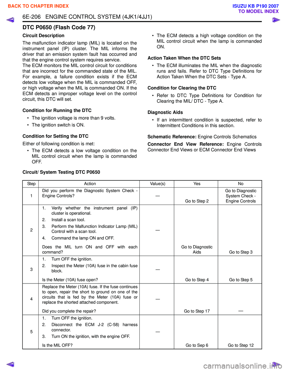
6E-206 ENGINE CONTROL SYSTEM (4JK1/4JJ1)
DTC P0650 (Flash Code 77)
Circuit Description
The malfunction indicator lamp (MIL) is located on the
instrument panel (IP) cluster. The MIL informs the
driver that an emission system fault has occurred and
that the engine control system requires service.
The ECM monitors the MIL control circuit for conditions
that are incorrect for the commanded state of the MIL.
For example, a failure condition exists if the ECM
detects low voltage when the MIL is commanded OFF,
or high voltage when the MIL is commanded ON. If the
ECM detects an improper voltage level on the control
circuit, this DTC will set.
Condition for Running the DTC • The ignition voltage is more than 9 volts.
• The ignition switch is ON.
Condition for Setting the DTC
Either of following condition is met: • The ECM detects a low voltage condition on the MIL control circuit when the lamp is commanded
OFF. • The ECM detects a high voltage condition on the
MIL control circuit when the lamp is commanded
ON.
Action Taken When the DTC Sets • The ECM illuminates the MIL when the diagnostic runs and fails. Refer to DTC Type Definitions for
Action Taken When the DTC Sets - Type A.
Condition for Clearing the DTC • Refer to DTC Type Definitions for Condition for Clearing the MIL/ DTC - Type A.
Diagnostic Aids • If an intermittent condition is suspected, refer to Intermittent Conditions in this section.
Schematic Reference: Engine Controls Schematics
Connector End View Reference: Engine Controls
Connector End Views or ECM Connector End Views
Circuit/ System Testing DTC P0650
Step Action Value(s)Yes No
1 Did you perform the Diagnostic System Check -
Engine Controls? —
Go to Step 2 Go to Diagnostic
System Check -
Engine Controls
2 1. Verify whether the instrument panel (IP)
cluster is operational.
2. Install a scan tool.
3. Perform the Malfunction Indicator Lamp (MIL) Control with a scan tool.
4. Command the lamp ON and OFF.
Does the MIL turn ON and OFF with each
command? —
Go to Diagnostic Aids Go to Step 3
3 1. Turn OFF the ignition.
2. Inspect the Meter (10A) fuse in the cabin fuse block.
Is the Meter (10A) fuse open? —
Go to Step 4 Go to Step 5
4 Replace the Meter (10A) fuse. If the fuse continues
to open, repair the short to ground on one of the
circuits that is fed by the Meter (10A) fuse or
replace the shorted attached component.
Did you complete the repair? —
Go to Step 17
—
51. Turn OFF the ignition.
2. Disconnect the ECM J-2 (C-58) harness connector.
3. Turn ON the ignition, with the engine OFF.
Is the MIL OFF? —
Go to Sep 6 Go to Step 12
BACK TO CHAPTER INDEX
TO MODEL INDEX
ISUZU KB P190 2007
Page 1874 of 6020
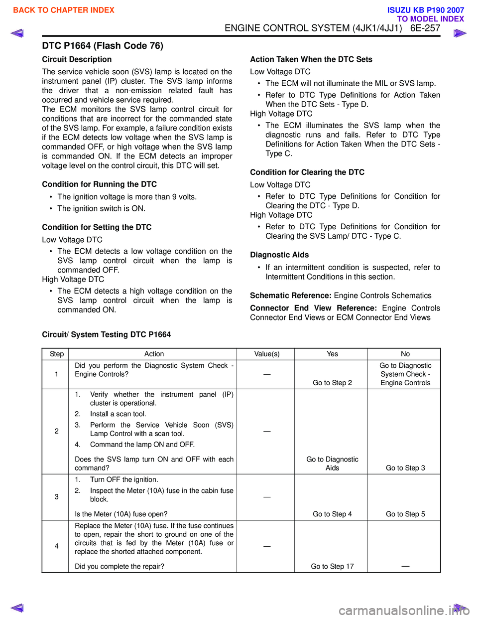
ENGINE CONTROL SYSTEM (4JK1/4JJ1) 6E-257
DTC P1664 (Flash Code 76)
Circuit Description
The service vehicle soon (SVS) lamp is located on the
instrument panel (IP) cluster. The SVS lamp informs
the driver that a non-emission related fault has
occurred and vehicle service required.
The ECM monitors the SVS lamp control circuit for
conditions that are incorrect for the commanded state
of the SVS lamp. For example, a failure condition exists
if the ECM detects low voltage when the SVS lamp is
commanded OFF, or high voltage when the SVS lamp
is commanded ON. If the ECM detects an improper
voltage level on the control circuit, this DTC will set.
Condition for Running the DTC • The ignition voltage is more than 9 volts.
• The ignition switch is ON.
Condition for Setting the DTC
Low Voltage DTC • The ECM detects a low voltage condition on the SVS lamp control circuit when the lamp is
commanded OFF.
High Voltage DTC
• The ECM detects a high voltage condition on the SVS lamp control circuit when the lamp is
commanded ON. Action Taken When the DTC Sets
Low Voltage DTC • The ECM will not illuminate the MIL or SVS lamp.
• Refer to DTC Type Definitions for Action Taken When the DTC Sets - Type D.
High Voltage DTC
• The ECM illuminates the SVS lamp when the diagnostic runs and fails. Refer to DTC Type
Definitions for Action Taken When the DTC Sets -
Type C.
Condition for Clearing the DTC
Low Voltage DTC • Refer to DTC Type Definitions for Condition for Clearing the DTC - Type D.
High Voltage DTC
• Refer to DTC Type Definitions for Condition for Clearing the SVS Lamp/ DTC - Type C.
Diagnostic Aids • If an intermittent condition is suspected, refer to Intermittent Conditions in this section.
Schematic Reference: Engine Controls Schematics
Connector End View Reference: Engine Controls
Connector End Views or ECM Connector End Views
Circuit/ System Testing DTC P1664
Step Action Value(s)Yes No
1 Did you perform the Diagnostic System Check -
Engine Controls? —
Go to Step 2 Go to Diagnostic
System Check -
Engine Controls
2 1. Verify whether the instrument panel (IP)
cluster is operational.
2. Install a scan tool.
3. Perform the Service Vehicle Soon (SVS) Lamp Control with a scan tool.
4. Command the lamp ON and OFF.
Does the SVS lamp turn ON and OFF with each
command? —
Go to Diagnostic Aids Go to Step 3
3 1. Turn OFF the ignition.
2. Inspect the Meter (10A) fuse in the cabin fuse block.
Is the Meter (10A) fuse open? —
Go to Step 4 Go to Step 5
4 Replace the Meter (10A) fuse. If the fuse continues
to open, repair the short to ground on one of the
circuits that is fed by the Meter (10A) fuse or
replace the shorted attached component.
Did you complete the repair? —
Go to Step 17
—
BACK TO CHAPTER INDEX
TO MODEL INDEX
ISUZU KB P190 2007
Page 1920 of 6020
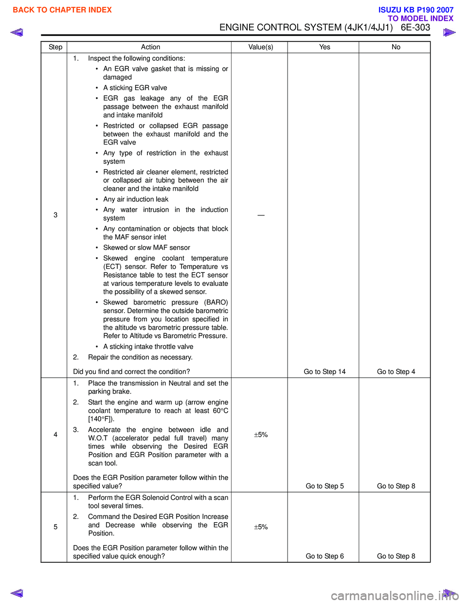
ENGINE CONTROL SYSTEM (4JK1/4JJ1) 6E-303
31. Inspect the following conditions:
• An EGR valve gasket that is missing ordamaged
• A sticking EGR valve
• EGR gas leakage any of the EGR passage between the exhaust manifold
and intake manifold
• Restricted or collapsed EGR passage between the exhaust manifold and the
EGR valve
• Any type of restriction in the exhaust system
• Restricted air cleaner element, restricted or collapsed air tubing between the air
cleaner and the intake manifold
• Any air induction leak
• Any water intrusion in the induction system
• Any contamination or objects that block the MAF sensor inlet
• Skewed or slow MAF sensor
• Skewed engine coolant temperature (ECT) sensor. Refer to Temperature vs
Resistance table to test the ECT sensor
at various temperature levels to evaluate
the possibility of a skewed sensor.
• Skewed barometric pressure (BARO) sensor. Determine the outside barometric
pressure from you location specified in
the altitude vs barometric pressure table.
Refer to Altitude vs Barometric Pressure.
• A sticking intake throttle valve
2. Repair the condition as necessary.
Did you find and correct the condition? —
Go to Step 14 Go to Step 4
4 1. Place the transmission in Neutral and set the
parking brake.
2. Start the engine and warm up (arrow engine coolant temperature to reach at least 60 °C
[140 °F]).
3. Accelerate the engine between idle and W.O.T (accelerator pedal full travel) many
times while observing the Desired EGR
Position and EGR Position parameter with a
scan tool.
Does the EGR Position parameter follow within the
specified value? ±
5%
Go to Step 5 Go to Step 8
5 1. Perform the EGR Solenoid Control with a scan
tool several times.
2. Command the Desired EGR Position Increase and Decrease while observing the EGR
Position.
Does the EGR Position parameter follow within the
specified value quick enough? ±
5%
Go to Step 6 Go to Step 8
Step
Action Value(s)Yes No
BACK TO CHAPTER INDEX
TO MODEL INDEX
ISUZU KB P190 2007
Page 1924 of 6020
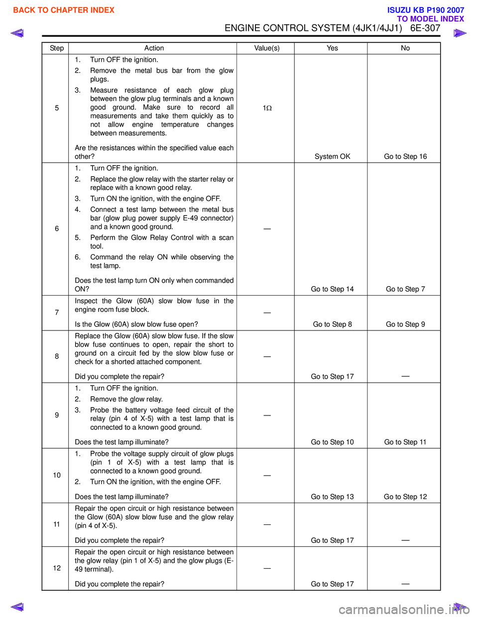
ENGINE CONTROL SYSTEM (4JK1/4JJ1) 6E-307
51. Turn OFF the ignition.
2. Remove the metal bus bar from the glow plugs.
3. Measure resistance of each glow plug between the glow plug terminals and a known
good ground. Make sure to record all
measurements and take them quickly as to
not allow engine temperature changes
between measurements.
Are the resistances within the specified value each
other? 1
Ω
System OK Go to Step 16
6 1. Turn OFF the ignition.
2. Replace the glow relay with the starter relay or replace with a known good relay.
3. Turn ON the ignition, with the engine OFF.
4. Connect a test lamp between the metal bus bar (glow plug power supply E-49 connector)
and a known good ground.
5. Perform the Glow Relay Control with a scan tool.
6. Command the relay ON while observing the test lamp.
Does the test lamp turn ON only when commanded
ON? —
Go to Step 14 Go to Step 7
7 Inspect the Glow (60A) slow blow fuse in the
engine room fuse block.
Is the Glow (60A) slow blow fuse open? —
Go to Step 8 Go to Step 9
8 Replace the Glow (60A) slow blow fuse. If the slow
blow fuse continues to open, repair the short to
ground on a circuit fed by the slow blow fuse or
check for a shorted attached component.
Did you complete the repair? —
Go to Step 17
—
91. Turn OFF the ignition.
2. Remove the glow relay.
3. Probe the battery voltage feed circuit of the relay (pin 4 of X-5) with a test lamp that is
connected to a known good ground.
Does the test lamp illuminate? —
Go to Step 10 Go to Step 11
10 1. Probe the voltage supply circuit of glow plugs
(pin 1 of X-5) with a test lamp that is
connected to a known good ground.
2. Turn ON the ignition, with the engine OFF.
Does the test lamp illuminate? —
Go to Step 13 Go to Step 12
11 Repair the open circuit or high resistance between
the Glow (60A) slow blow fuse and the glow relay
(pin 4 of X-5).
Did you complete the repair? —
Go to Step 17
—
12Repair the open circuit or high resistance between
the glow relay (pin 1 of X-5) and the glow plugs (E-
49 terminal).
Did you complete the repair? —
Go to Step 17
—
Step Action Value(s)Yes No
BACK TO CHAPTER INDEX
TO MODEL INDEX
ISUZU KB P190 2007