2007 ISUZU KB P190 Wiring
[x] Cancel search: WiringPage 3411 of 6020
Engine Management – V6 – Diagnostics Page 6C1-2–133
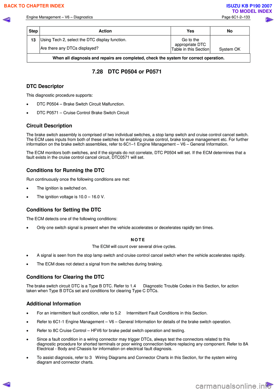
Step Action Yes No
13 Using Tech 2, select the DTC display function.
Are there any DTCs displayed? Go to the
appropriate DTC
Table in this Section System OK
When all diagnosis and repairs are completed, check the system for correct operation.
7.28 DTC P0504 or P0571
DTC Descriptor
This diagnostic procedure supports:
• DTC P0504 – Brake Switch Circuit Malfunction.
• DTC P0571 – Cruise Control Brake Switch Circuit
Circuit Description
The brake switch assembly is comprised of two individual switches, a stop lamp switch and cruise control cancel switch.
The ECM uses inputs from both of these switches for enabling cruise control, brake torque management etc. For further
information on the brake switch assemblies, refer to 6C1–1 Engine Management – V6 – General Information.
The ECM monitors both switches, and if the signals do not correlate, DTC P0504 will set. If the ECM determines that a
fault exists in the cruise control cancel circuit, DTC0571 will set.
Conditions for Running the DTC
Run continuously once the following conditions are met:
• The ignition is switched on.
• The ignition voltage is 10.0 – 16.0 V.
Conditions for Setting the DTC
The ECM detects one of the following conditions:
• Only one switch signal is present when the vehicle accelerates or decelerates rapidly ten times.
NOTE
The ECM will count over several drive cycles.
• A signal is seen from the stop lamp switch and cruise control cancel switch when the vehicle accelerates rapidly.
• The ECM does not detect a signal from the switches during braking.
Conditions for Clearing the DTC
The brake switch circuit DTC is a Type B DTC. Refer to 1.4 Diagnostic Trouble Codes in this Section, for action
taken when Type B DTCs set and conditions for clearing Type C DTCs.
Additional Information
• For an intermittent fault condition, refer to 5.2 Intermittent Fault Conditions in this Section.
• Refer to 6C1-1 Engine Management – V6 – General Information for details of the brake switch operation.
• Refer to 8C Cruise Control – HFV6 for brake pedal switch operation and testing.
• Since a fault condition in a wiring connector may trigger DTCs, always test the connectors related to this
diagnostic procedure for shorted terminals or poor wiring connection before replacing any component. Refer to 8A
Electrical - Body and Chassis for information on electrical fault diagnosis.
• To assist diagnosis, refer to 3 W iring Diagrams and Connector Charts in this Section, for the system wiring
diagram and connector charts.
BACK TO CHAPTER INDEX
TO MODEL INDEX
ISUZU KB P190 2007
Page 3412 of 6020
Engine Management – V6 – Diagnostics Page 6C1-2–134
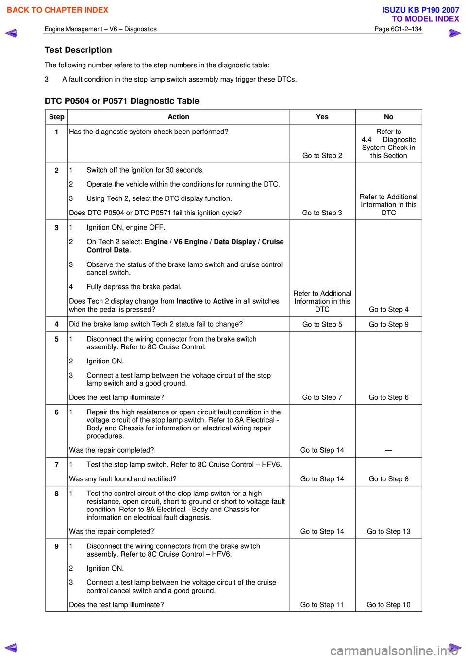
Test Description
The following number refers to the step numbers in the diagnostic table:
3 A fault condition in the stop lamp switch assembly may trigger these DTCs.
DTC P0504 or P0571 Diagnostic Table
Step Action Yes No
1 Has the diagnostic system check been performed?
Go to Step 2 Refer to
4.4 Diagnostic System Check in this Section
2 1 Switch off the ignition for 30 seconds.
2 Operate the vehicle within the conditions for running the DTC.
3 Using Tech 2, select the DTC display function.
Does DTC P0504 or DTC P0571 fail this ignition cycle? Go to Step 3 Refer to Additional
Information in this DTC
3 1 Ignition ON, engine OFF.
2 On Tech 2 select: Engine / V6 Engine / Data Display / Cruise
Control Data .
3 Observe the status of the brake lamp switch and cruise control cancel switch.
4 Fully depress the brake pedal.
Does Tech 2 display change from Inactive to Active in all switches
when the pedal is pressed? Refer to Additional
Information in this DTC Go to Step 4
4 Did the brake lamp switch Tech 2 status fail to change?
Go to Step 5 Go to Step 9
5 1 Disconnect the wiring connector from the brake switch
assembly. Refer to 8C Cruise Control.
2 Ignition ON.
3 Connect a test lamp between the voltage circuit of the stop lamp switch and a good ground.
Does the test lamp illuminate? Go to Step 7 Go to Step 6
6 1 Repair the high resistance or open circuit fault condition in the
voltage circuit of the stop lamp switch. Refer to 8A Electrical -
Body and Chassis for information on electrical wiring repair
procedures.
W as the repair completed? Go to Step 14 —
7 1 Test the stop lamp switch. Refer to 8C Cruise Control – HFV6.
W as any fault found and rectified? Go to Step 14 Go to Step 8
8 1 Test the control circuit of the stop lamp switch for a high
resistance, open circuit, short to ground or short to voltage fault
condition. Refer to 8A Electrical - Body and Chassis for
information on electrical fault diagnosis.
W as the repair completed? Go to Step 14 Go to Step 13
9 1 Disconnect the wiring connectors from the brake switch
assembly. Refer to 8C Cruise Control – HFV6.
2 Ignition ON.
3 Connect a test lamp between the voltage circuit of the cruise control cancel switch and a good ground.
Does the test lamp illuminate? Go to Step 11 Go to Step 10
BACK TO CHAPTER INDEX
TO MODEL INDEX
ISUZU KB P190 2007
Page 3413 of 6020
Engine Management – V6 – Diagnostics Page 6C1-2–135
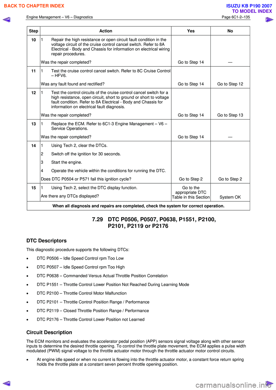
Step Action Yes No
10 1 Repair the high resistance or open circuit fault condition in the
voltage circuit of the cruise control cancel switch. Refer to 8A
Electrical - Body and Chassis for information on electrical wiring
repair procedures.
W as the repair completed? Go to Step 14 —
11 1 Test the cruise control cancel switch. Refer to 8C Cruise Control
– HFV6.
W as any fault found and rectified? Go to Step 14 Go to Step 12
12 1 Test the control circuits of the cruise control cancel switch for a
high resistance, open circuit, short to ground or short to voltage
fault condition. Refer to 8A Electrical - Body and Chassis for
information on electrical fault diagnosis.
W as the repair completed? Go to Step 14 Go to Step 13
13 1 Replace the ECM. Refer to 6C1-3 Engine Management – V6 –
Service Operations.
W as the repair completed? Go to Step 14 —
14 1 Using Tech 2, clear the DTCs.
2 Switch off the ignition for 30 seconds.
3 Start the engine.
4 Operate the vehicle within the conditions for running the DTC.
Does DTC P0504 or P571 fail this ignition cycle? Go to Step 2 Go to Step 2
15 1 Using Tech 2, select the DTC display function.
Are there any DTCs displayed? Go to the
appropriate DTC
Table in this Section System OK
When all diagnosis and repairs are completed, check the system for correct operation.
7.29 DTC P0506, P0507, P0638, P1551, P2100,
P2101, P2119 or P2176
DTC Descriptors
This diagnostic procedure supports the following DTCs:
• DTC P0506 – Idle Speed Control rpm Too Low
• DTC P0507 – Idle Speed Control rpm Too High
• DTC P0638 – Commanded Versus Actual Throttle Position Correlation
• DTC P1551 – Throttle Control Lower Position Not Reached During Learning Mode
• DTC P2100 – Throttle Control Motor Malfunction
• DTC P2101 – Throttle Control Position Range / Performance
• DTC P2119 – Closed Throttle Position Range / Performance
• DTC P2176 – Throttle Control Lower Position not Learned
Circuit Description
The ECM monitors and evaluates the accelerator pedal position (APP) sensors signal voltage along with other sensor
inputs to determine the desired throttle opening. To control the throttle plate movement, the ECM applies a pulse width
modulated (PW M) signal voltage to the throttle actuator motor through the throttle actuator motor control circuits.
• At engine idle speed or when no current is flowing into the throttle actuator motor, a constant force return spring
holds the throttle plate at a constant seven percent throttle opening position.
BACK TO CHAPTER INDEX
TO MODEL INDEX
ISUZU KB P190 2007
Page 3415 of 6020
Engine Management – V6 – Diagnostics Page 6C1-2–137
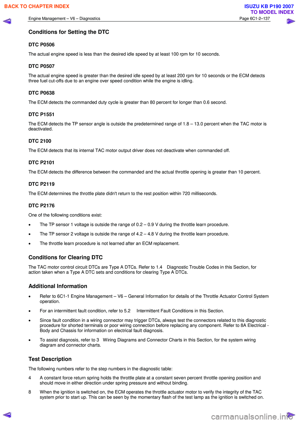
Conditions for Setting the DTC
DTC P0506
The actual engine speed is less than the desired idle speed by at least 100 rpm for 10 seconds.
DTC P0507
The actual engine speed is greater than the desired idle speed by at least 200 rpm for 10 seconds or the ECM detects
three fuel cut-offs due to an engine over speed condition while the engine is idling.
DTC P0638
The ECM detects the commanded duty cycle is greater than 80 percent for longer than 0.6 second.
DTC P1551
The ECM detects the TP sensor angle is outside the predetermined range of 1.8 – 13.0 percent when the TAC motor is
deactivated.
DTC 2100
The ECM detects that its internal TAC motor output driver does not deactivate when commanded off.
DTC P2101
The ECM detects the difference between the commanded and the actual throttle opening is greater than 10 percent.
DTC P2119
The ECM determines the throttle plate didn't return to the rest position within 720 milliseconds.
DTC P2176
One of the following conditions exist:
• The TP sensor 1 voltage is outside the range of 0.2 – 0.9 V during the throttle learn procedure.
• The TP sensor 2 voltage is outside the range of 4.2 – 4.8 V during the throttle learn procedure.
• The throttle learn procedure is not learned after an ECM replacement.
Conditions for Clearing DTC
The TAC motor control circuit DTCs are Type A DTCs. Refer to 1.4 Diagnostic Trouble Codes in this Section, for
action taken when a Type A DTC sets and conditions for clearing Type A DTCs.
Additional Information
• Refer to 6C1-1 Engine Management – V6 – General Information for details of the Throttle Actuator Control System
operation.
• For an intermittent fault condition, refer to 5.2 Intermittent Fault Conditions in this Section.
• Since fault condition in a wiring connector may trigger DTCs, always test the connectors related to this diagnostic
procedure for shorted terminals or poor wiring connection before replacing any component. Refer to 8A Electrical -
Body and Chassis for information on electrical fault diagnosis.
• To assist diagnosis, refer to 3 W iring Diagrams and Connector Charts in this Section, for the system wiring
diagram and connector charts.
Test Description
The following numbers refer to the step numbers in the diagnostic table:
4 A constant force return spring holds the throttle plate at a constant seven percent throttle opening position and should move in either direction under spring pressure and without binding.
8 W hen the ignition is switched on, the ECM operates the throttle actuator motor to verify the integrity of the TAC system prior to start up. This can be seen by the momentary flash of the test lamp as the ignition is switched on.
BACK TO CHAPTER INDEX
TO MODEL INDEX
ISUZU KB P190 2007
Page 3416 of 6020
Engine Management – V6 – Diagnostics Page 6C1-2–138
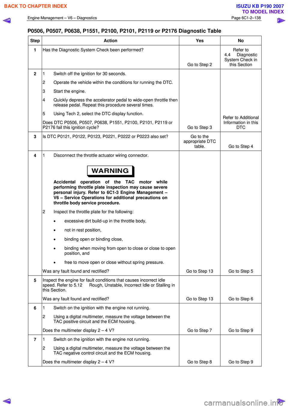
P0506, P0507, P0638, P1551, P2100, P2101, P2119 or P2176 Diagnostic Table
Step Action Yes No
1 Has the Diagnostic System Check been performed?
Go to Step 2 Refer to
4.4 Diagnostic
System Check in this Section
2 1 Switch off the ignition for 30 seconds.
2 Operate the vehicle within the conditions for running the DTC.
3 Start the engine.
4 Quickly depress the accelerator pedal to wide-open throttle then release pedal. Repeat this procedure several times.
5 Using Tech 2, select the DTC display function.
Does DTC P0506, P0507, P0638, P1551, P2100, P2101, P2119 or
P2176 fail this ignition cycle? Go to Step 3 Refer to Additional
Information in this DTC
3 Is DTC P0121, P0122, P0123, P0221, P0222 or P0223 also set? Go to the
appropriate DTC table. Go to Step 4
4 1 Disconnect the throttle actuator wiring connector.
Accidental operation of the TAC motor while
performing throttle plate inspection may cause severe
personal injury. Refer to 6C1-3 Engine Management –
V6 – Service Operations for additional precautions on
throttle body service procedure.
2 Inspect the throttle plate for the following:
• excessive dirt build-up in the throttle body,
• not in rest position,
• binding open or binding close,
• binding when moving from open to close or close to open
position, and
• free to move open or close without spring pressure.
W as any fault found and rectified? Go to Step 13 Go to Step 5
5 Inspect the engine for fault conditions that causes incorrect idle
speed. Refer to 5.12 Rough, Unstable, Incorrect Idle or Stalling in
this Section.
W as any fault found and rectified? Go to Step 13 Go to Step 6
6 1 Switch on the ignition with the engine not running.
2 Using a digital multimeter, measure the voltage between the TAC positive circuit and the ECM housing.
Does the multimeter display 2 – 4 V? Go to Step 7 Go to Step 9
7 1 Switch on the ignition with the engine not running.
2 Using a digital multimeter, measure the voltage between the TAC negative control circuit and the ECM housing.
Does the multimeter display 2 – 4 V? Go to Step 8 Go to Step 9
BACK TO CHAPTER INDEX
TO MODEL INDEX
ISUZU KB P190 2007
Page 3419 of 6020
Engine Management – V6 – Diagnostics Page 6C1-2–141
Conditions for Clearing the DTC
Refer to 1.4 Diagnostic Trouble Codes in this Section, for action taken when a Type B DTC sets and conditions for
clearing Type B DTCs.
Additional Information
• Refer to 6C1-1 Engine Management –V6 – General Information for details of the ECM operation.
• Refer to 11A Immobiliser for the following information:
• ICU link to PIM, and
• Immobiliser System.
• Since a fault condition in a wiring connector may trigger DTCs, always test the connectors related to this
diagnostic procedure for shorted terminals or poor wiring connection before replacing any component. Refer to 8A
Electrical - Body and Chassis for information on electrical fault diagnosis.
• For an intermittent fault condition, refer to 5.2 Intermittent Fault Conditions in this Section.
• To assist diagnosis, refer to 3 W iring Diagrams and Connector Charts in this Section, for the system wiring
diagram and connector charts.
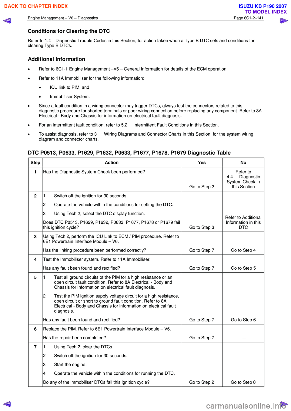
DTC P0513, P0633, P1629, P1632, P0633, P1677, P1678, P1679 Diagnostic Table
Step Action Yes No
1 Has the Diagnostic System Check been performed?
Go to Step 2 Refer to
4.4 Diagnostic
System Check in this Section
2 1 Switch off the ignition for 30 seconds.
2 Operate the vehicle within the conditions for setting the DTC.
3 Using Tech 2, select the DTC display function.
Does DTC P0513, P1629, P1632, P0633, P1677, P1678 or P1679 fail
this ignition cycle? Go to Step 3 Refer to Additional
Information in this DTC
3 Using Tech 2, perform the ICU Link to ECM / PIM procedure. Refer to
6E1 Powertrain Interface Module – V6.
Has the linking procedure been performed correctly? Go to Step 7 Go to Step 4
4 Test the Immobiliser system. Refer to 11A Immobiliser.
Has any fault been found and rectified? Go to Step 7 Go to Step 5
5 1 Test all ground circuits of the PIM for a high resistance or an
open circuit fault condition. Refer to 8A Electrical - Body and
Chassis for information on electrical fault diagnosis.
2 Test the PIM ignition supply voltage circuit for a high resistance, open circuit or short to ground fault condition. Refer to 8A
Electrical - Body and Chassis for information on electrical fault
diagnosis.
Has any fault been found and rectified? Go to Step 7 Go to Step 6
6 Replace the PIM. Refer to 6E1 Powertrain Interface Module – V6.
Has the repair been completed? Go to Step 7 —
7 1 Using Tech 2, clear the DTCs.
2 Switch off the ignition for 30 seconds.
3 Start the engine.
4 Operate the vehicle within the conditions for running the DTC.
Do any of the immobiliser DTCs fail this ignition cycle? Go to Step 2 Go to Step 8
BACK TO CHAPTER INDEX
TO MODEL INDEX
ISUZU KB P190 2007
Page 3420 of 6020
Engine Management – V6 – Diagnostics Page 6C1-2–142
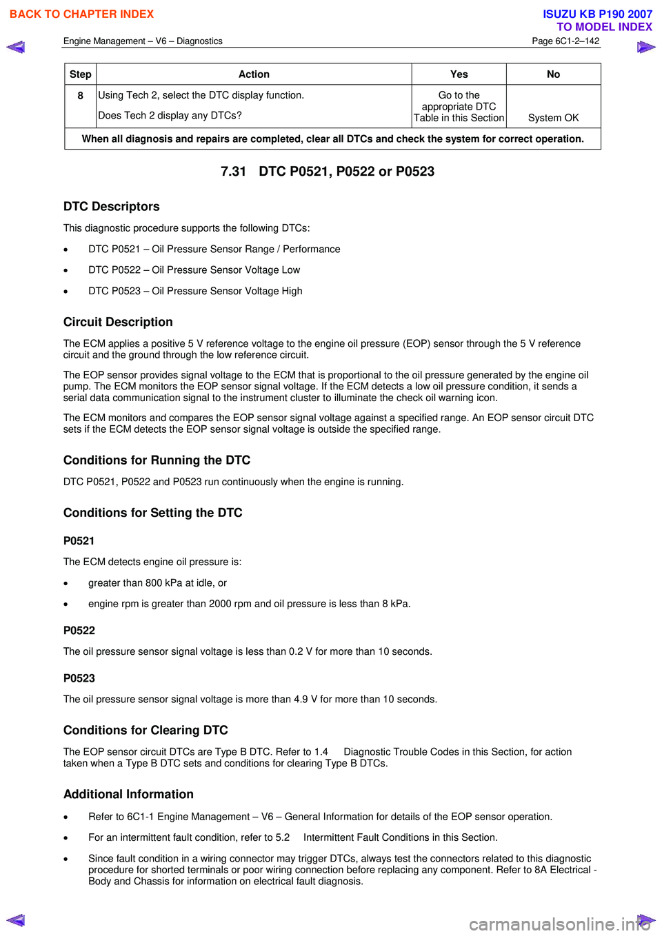
Step Action Yes No
8 Using Tech 2, select the DTC display function.
Does Tech 2 display any DTCs? Go to the
appropriate DTC
Table in this Section System OK
When all diagnosis and repairs are completed, clear all DTCs and check the system for correct operation.
7.31 DTC P0521, P0522 or P0523
DTC Descriptors
This diagnostic procedure supports the following DTCs:
• DTC P0521 – Oil Pressure Sensor Range / Performance
• DTC P0522 – Oil Pressure Sensor Voltage Low
• DTC P0523 – Oil Pressure Sensor Voltage High
Circuit Description
The ECM applies a positive 5 V reference voltage to the engine oil pressure (EOP) sensor through the 5 V reference
circuit and the ground through the low reference circuit.
The EOP sensor provides signal voltage to the ECM that is proportional to the oil pressure generated by the engine oil
pump. The ECM monitors the EOP sensor signal voltage. If the ECM detects a low oil pressure condition, it sends a
serial data communication signal to the instrument cluster to illuminate the check oil warning icon.
The ECM monitors and compares the EOP sensor signal voltage against a specified range. An EOP sensor circuit DTC
sets if the ECM detects the EOP sensor signal voltage is outside the specified range.
Conditions for Running the DTC
DTC P0521, P0522 and P0523 run continuously when the engine is running.
Conditions for Setting the DTC
P0521
The ECM detects engine oil pressure is:
• greater than 800 kPa at idle, or
• engine rpm is greater than 2000 rpm and oil pressure is less than 8 kPa.
P0522
The oil pressure sensor signal voltage is less than 0.2 V for more than 10 seconds.
P0523
The oil pressure sensor signal voltage is more than 4.9 V for more than 10 seconds.
Conditions for Clearing DTC
The EOP sensor circuit DTCs are Type B DTC. Refer to 1.4 Diagnostic Trouble Codes in this Section, for action
taken when a Type B DTC sets and conditions for clearing Type B DTCs.
Additional Information
• Refer to 6C1-1 Engine Management – V6 – General Information for details of the EOP sensor operation.
• For an intermittent fault condition, refer to 5.2 Intermittent Fault Conditions in this Section.
• Since fault condition in a wiring connector may trigger DTCs, always test the connectors related to this diagnostic
procedure for shorted terminals or poor wiring connection before replacing any component. Refer to 8A Electrical -
Body and Chassis for information on electrical fault diagnosis.
BACK TO CHAPTER INDEX
TO MODEL INDEX
ISUZU KB P190 2007
Page 3421 of 6020
Engine Management – V6 – Diagnostics Page 6C1-2–143
• To assist diagnosis, refer to 3 W iring Diagrams and Connector Charts in this Section, for the system wiring
diagram and connector charts.
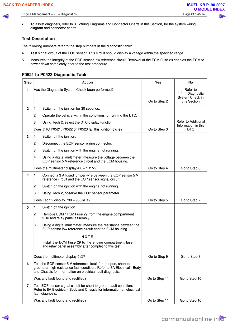
Test Description
The following numbers refer to the step numbers in the diagnostic table:
4 Test signal circuit of the EOP sensor. This circuit should display a voltage within the specified range.
5 Measures the integrity of the EOP sensor low reference circuit. Removal of the ECM Fuse 29 enables the ECM to power down completely prior to the test procedure.
P0521 to P0523 Diagnostic Table
Step Action Yes No
1 Has the Diagnostic System Check been performed?
Go to Step 2 Refer to
4.4 Diagnostic
System Check in this Section
2 1 Switch off the ignition for 30 seconds.
2 Operate the vehicle within the conditions for running the DTC.
3 Using Tech 2, select the DTC display function.
Does DTC P0521, P0522 or P0523 fail this ignition cycle? Go to Step 3 Refer to Additional
Information in this DTC
3 1 Switch off the ignition.
2 Disconnect the EOP sensor wiring connector.
3 Switch on the ignition with the engine not running.
4 Using a digital multimeter, measure the voltage between the EOP sensor 5 V reference circuit and the ECM housing.
Does the multimeter display 4.8 – 5.2 V? Go to Step 4 Go to Step 6
4 1 Connect a 3 A fused jumper wire between the EOP sensor 5 V
reference circuit and the EOP sensor signal circuit.
2 Switch on the ignition with the engine not running.
3 Using Tech 2, observe the EOP sensor parameter.
Does Tech 2 display 780 – 980 kPa? Go to Step 5 Go to Step 7
5 1 Switch off the ignition.
2 Remove ECM / TCM Fuse 29 from the engine compartment fuse and relay panel assembly.
3 Using a digital multimeter, measure the resistance between the EOP sensor low reference circuit and the ECM housing.
NOTE
Install the ECM Fuse 29 to the engine compartment fuse
and relay panel assembly after completing this test.
Does the multimeter display 5 Ω? Go to Step 9 Go to Step 8
6 Test the EOP sensor 5 V reference circuit for an open, short to
ground or high resistance fault condition. Refer to 8A Electrical - Body
and Chassis for information on electrical fault diagnosis.
W as any fault found and rectified? Go to Step 11 Go to Step 10
7 Test EOP sensor signal circuit for short to ground fault condition.
Refer to 8A Electrical - Body and Chassis for information on electrical
fault diagnosis.
W as any fault found and rectified? Go to Step 11 Go to Step 10
BACK TO CHAPTER INDEX
TO MODEL INDEX
ISUZU KB P190 2007