Page 1437 of 6020
ENGINE MECHANICAL (4JK1/4JJ1) 6A-77
28. Remove the turbocharger water feed pipe (1) and
hose.
RTW 56ASH019101
29. Remove the turbocharger engine oil feed pipe.
30. Remove the engine oil level gauge guide tube.
31. Remove the fuel return pipe and hose (1).
RTW 56ASH019201
32. Remove the fuel injection pipe clip.
33. Remove the fuel injection pipe.
34. Remove the vacuum hose (1).
RTW 66ASH003101
35. Remove the noise cover (1).
RTW 56CSH001401
BACK TO CHAPTER INDEX
TO MODEL INDEX
ISUZU KB P190 2007
Page 1439 of 6020
ENGINE MECHANICAL (4JK1/4JJ1) 6A-79
44. Remove the camshaft bearing cap.
RTW 56ASH018401
45. Remove the camshaft.
46. Remove the rocker arm shaft assembly.
Note:
Keep the removed rocker arm shaft assembly properl
y
so that they may be put back to the original place.
RTW 56ASH012201
Legend
1. Exhaust Rocker Arm Shaft Assembly
2. Bolt (Long)
3. Bolt (Short)
4. Intake Rocker Arm Shaft Assembly
5. Front
Note:
Pay full attention so as not to drop the parts in the gea
r
case of the front part of the cylinder head or a hole into
which oil pours back in the front.
Note:
Remember the original position.
47. Remove the timing chain tensioner.
RTW 56CSH003701
Legend
1. Timing Chain Tensioner
2. Gasket
3. Nut
48. Remove the idle gear D.
• Timing chain is dropped behind.
RTW 56ASH022101
BACK TO CHAPTER INDEX
TO MODEL INDEX
ISUZU KB P190 2007
Page 1442 of 6020
6A-82 ENGINE MECHANICAL (4JK1/4JJ1)
10. Remove the intake and exhaust valve.
• Sort the removed valves according to cylinders
by using tags others.
LNW 21BSH016801
11. Remove the valve stem oil seal.
• Refer to procedure for valve stem and valve in
this manual.
12. Remove the spring lower seat.
13. Remove the valve guide. • Use the valve guide replacer to press out the
valve guides from the bottom side of the
cylinder head.
Special tool
Valve guide remover and installer:
5-8840-2816-0
RTW 56ASH008701
14. Remove the cam end gasket (1).
RTW 56ASH020501
15. Remove the oil seal.
RTW 56ASH008801
BACK TO CHAPTER INDEX
TO MODEL INDEX
ISUZU KB P190 2007
Page 1447 of 6020

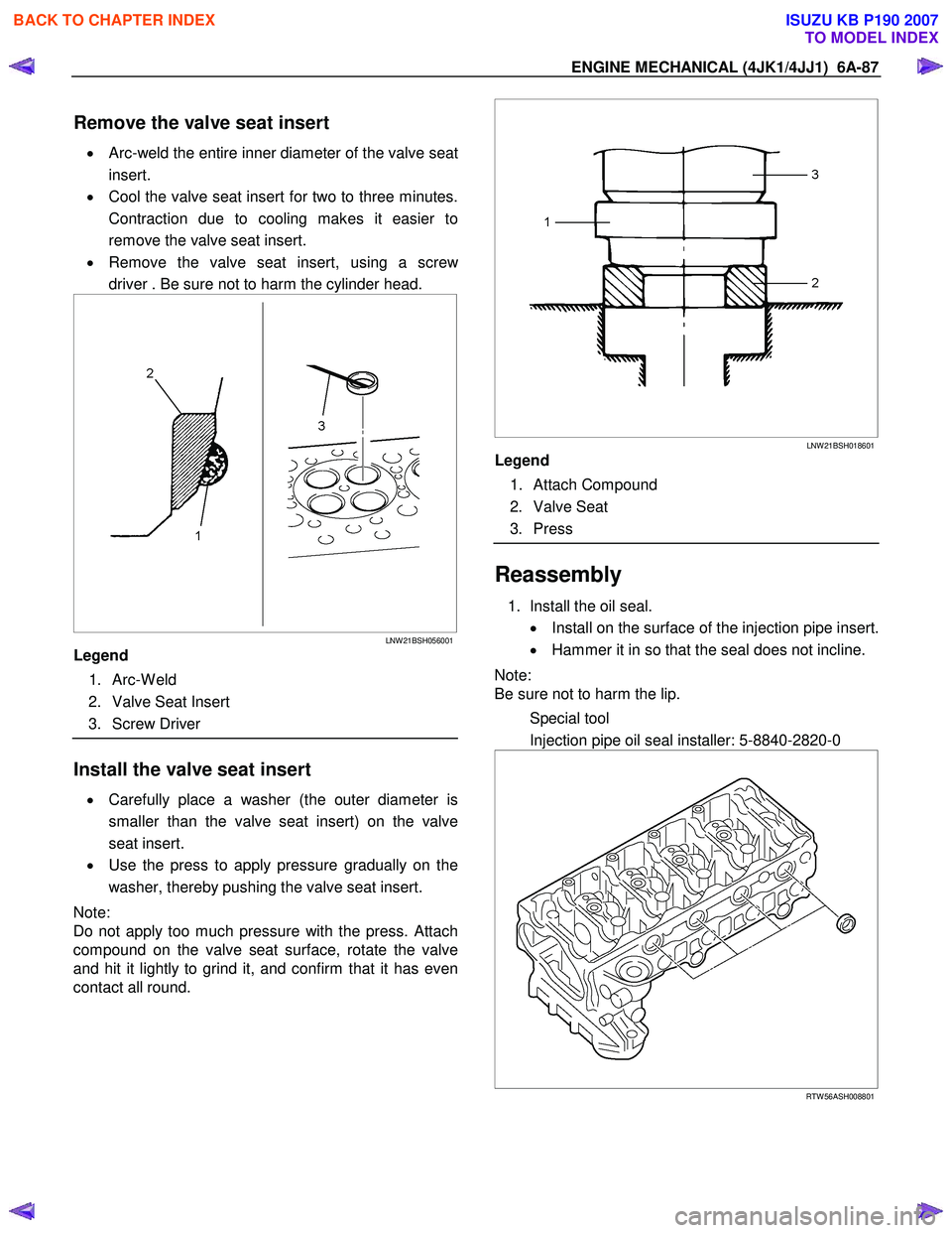
ENGINE MECHANICAL (4JK1/4JJ1) 6A-87
Remove the valve seat insert
• Arc-weld the entire inner diameter of the valve seat
insert.
• Cool the valve seat insert for two to three minutes.
Contraction due to cooling makes it easier to
remove the valve seat insert.
• Remove the valve seat insert, using a scre
w
driver . Be sure not to harm the cylinder head.
LNW 21BSH056001
Legend
1. Arc-W eld
2. Valve Seat Insert
3. Screw Driver
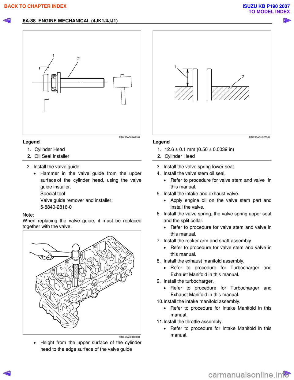
Install the valve seat insert
• Carefully place a washer (the outer diameter is
smaller than the valve seat insert) on the valve
seat insert.
• Use the press to apply pressure gradually on the
washer, thereby pushing the valve seat insert.
Note:
Do not apply too much pressure with the press. Attach
compound on the valve seat surface, rotate the valve
and hit it lightly to grind it, and confirm that it has even
contact all round.
LNW 21BSH018601
Legend
1. Attach Compound
2. Valve Seat
3. Press
Reassembly
1. Install the oil seal.
• Install on the surface of the injection pipe insert.
• Hammer it in so that the seal does not incline.
Note:
Be sure not to harm the lip.
Special tool
Injection pipe oil seal installer: 5-8840-2820-0
RTW 56ASH008801
BACK TO CHAPTER INDEX
TO MODEL INDEX
ISUZU KB P190 2007
Page 1448 of 6020

6A-88 ENGINE MECHANICAL (4JK1/4JJ1)
RTW 56ASH009101
Legend
1. Cylinder Head
2. Oil Seal Installer
2. Install the valve guide.
• Hammer in the valve guide from the uppe
r
surface of the cylinder head, using the valve
guide installer.
Special tool
Valve guide remover and installer:
5-8840-2816-0
Note:
W hen replacing the valve guide, it must be replaced
together with the valve.
RTW 56ASH009001
• Height from the upper surface of the cylinder
head to the edge surface of the valve guide
RTW 56ASH023001
Legend
1. 12.6 ± 0.1 mm (0.50 ± 0.0039 in)
2. Cylinder Head
3. Install the valve spring lower seat.
4. Install the valve stem oil seal. • Refer to procedure for valve stem and valve in
this manual.
5. Install the intake and exhaust valve. • Apply engine oil on the valve stem part and
install the valve.
6. Install the valve spring, the valve spring upper seat and the split collar.
• Refer to procedure for valve stem and valve in
this manual.
7. Install the rocker arm and shaft assembly. • Refer to procedure for valve stem and valve in
this manual.
8. Install the exhaust manifold assembly. • Refer to procedure for Turbocharger and
Exhaust Manifold in this manual.
9. Install the turbocharger. • Refer to procedure for Turbocharger and
Exhaust Manifold in this manual.
10. Install the intake manifold assembly. • Refer to procedure for Intake Manifold in this
manual.
11. Install the throttle assembly. • Refer to procedure for Intake Manifold in this
manual.
BACK TO CHAPTER INDEX
TO MODEL INDEX
ISUZU KB P190 2007
Page 1451 of 6020
ENGINE MECHANICAL (4JK1/4JJ1) 6A-91
RTW 56ASH009701
Special tool
Angle gauge: 5-8840-0266-0
12. Install the cylinder head gear case bolt and nut.
• Tighten the nuts (1) and bolts (2) to the
specified torque.
Tightening torque: 25 N ⋅
⋅⋅
⋅
m (2.5 kg ⋅
⋅⋅
⋅
m / 18 lb ft)
RTW 56ASH020801
13. Install the water by pass pipe.
Apply soapy water to the O-ring.
Tighten the bolt to the specified torque.
Tightening torque: 25 N ⋅
⋅⋅
⋅
m (2.5 kg ⋅
⋅⋅
⋅
m / 18 lb ft)
14. Install the vacuum hose (1).
RTW 66ASH003101
15. Install the rocker arm shaft assembly.
• Apply the engine oil.
• Attach the rocker arm shaft assembly in
sequence from No.1 to No.4.
Tightening torque: 21 N ⋅
⋅⋅
⋅
m (2.1 kg ⋅
⋅⋅
⋅
m / 15 lb ft)
RTW 56ASH012201
Legend
1. Exhaust Rocker Arm Shaft Assembly
2. Bolt (Long)
3. Bolt (Short)
4. Intake Rocker Arm Shaft Assembly
5. Front
BACK TO CHAPTER INDEX
TO MODEL INDEX
ISUZU KB P190 2007
Page 1452 of 6020
6A-92 ENGINE MECHANICAL (4JK1/4JJ1)
16. Install the chain guide bolt from cylinder head.
Tighten the bolt to the specified torque.
Tightening torque: 25 N ⋅
⋅⋅
⋅
m (2.5 kg ⋅
⋅⋅
⋅
m/18 lb ft)
RTW 56ASH019501
17. Install the tension lever.
18. Rotate the crankshaft to make the No.1 cylinde
r
meet the compression top dead center (TDC).
RTW 76ASH001301
Legend
1. TDC
19. Install the timing chain with idle gear D.
• Apply the engine oil bolt thread and seat.
Tightening torque : 59 N ⋅
⋅⋅
⋅
m (6.0 kg ⋅
⋅⋅
⋅
m/43 lb ft)
RTW 56ASH021801
• Align the timing marks at two locations as
shown.
RTW 56ASH020301
Legend
1. Timing Chain
2. Timing Mark
3. Blue Link
4. Yellow Link
BACK TO CHAPTER INDEX
TO MODEL INDEX
ISUZU KB P190 2007
Page 1454 of 6020
6A-94 ENGINE MECHANICAL (4JK1/4JJ1)
24. Install the camshaft assembly.
• Align timing mark on intake camshaft and
exhaust camshaft to idle gear D.
RTW 56ASH007001
Legend
1. Exhaust Camshaft Gear
2. Intake Camshaft Gear
3. Idle Gear D
25. Install the camshaft bearing cap.
•
Apply engine oil to all of the cylinder head
journals.
RTW 56ASH013801
Tightening torque: 18 N ⋅
⋅⋅
⋅
m (1.8 kg ⋅
⋅⋅
⋅
m / 13 lb ft)
26. Align mark on camshaft to mark on camshaft
bearing cap.
• Align mark (1) on intake camshaft and exhaust
camshaft to mark of bearing cap.
RTW 56ASH006901
27. Remove the lock bolt from the camshaft gear.
28. Turn the crank pulley two rotation (720 °CA).
• Align mark on camshaft to mark on camshaft
bearing cap.
RTW 56ASH020701
Legend
1. Exhaust Camshaft Gear
2. Intake Camshaft Gear
3. Idle Gear D
BACK TO CHAPTER INDEX
TO MODEL INDEX
ISUZU KB P190 2007