Page 1468 of 6020

6A-108 ENGINE MECHANICAL (4JK1/4JJ1)
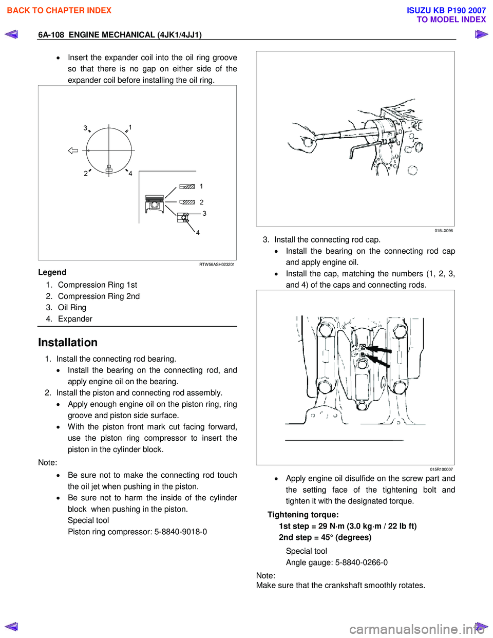
• Insert the expander coil into the oil ring groove
so that there is no gap on either side of the
expander coil before installing the oil ring.
RTW 56ASH023201
Legend
1. Compression Ring 1st
2. Compression Ring 2nd
3. Oil Ring
4. Expander
Installation
1. Install the connecting rod bearing.
• Install the bearing on the connecting rod, and
apply engine oil on the bearing.
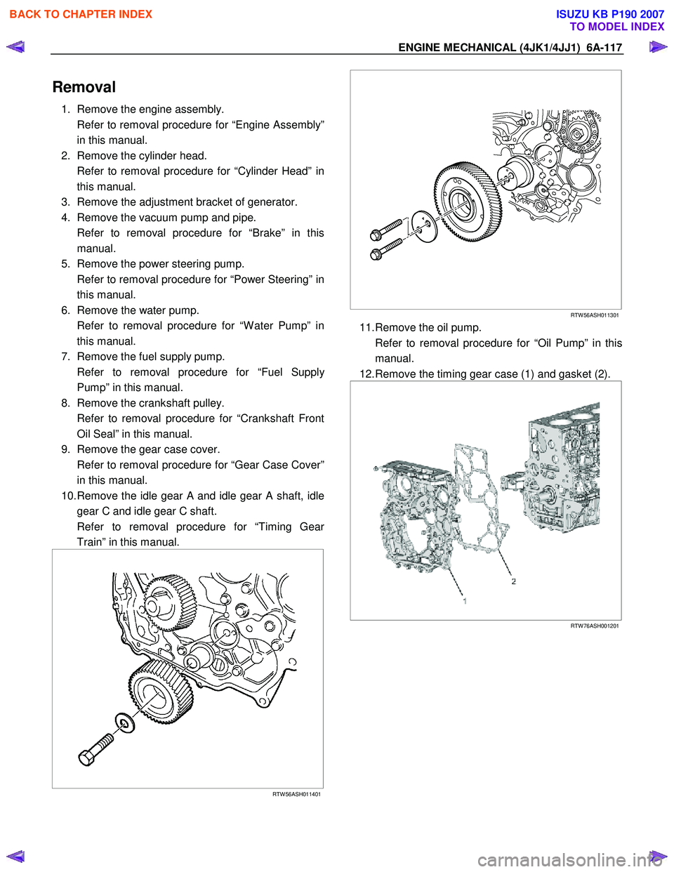
2. Install the piston and connecting rod assembly. • Apply enough engine oil on the piston ring, ring
groove and piston side surface.
• W ith the piston front mark cut facing forward,
use the piston ring compressor to insert the
piston in the cylinder block.
Note: • Be sure not to make the connecting rod touch
the oil jet when pushing in the piston.
• Be sure not to harm the inside of the cylinde
r
block when pushing in the piston.
Special tool
Piston ring compressor: 5-8840-9018-0
015LX096
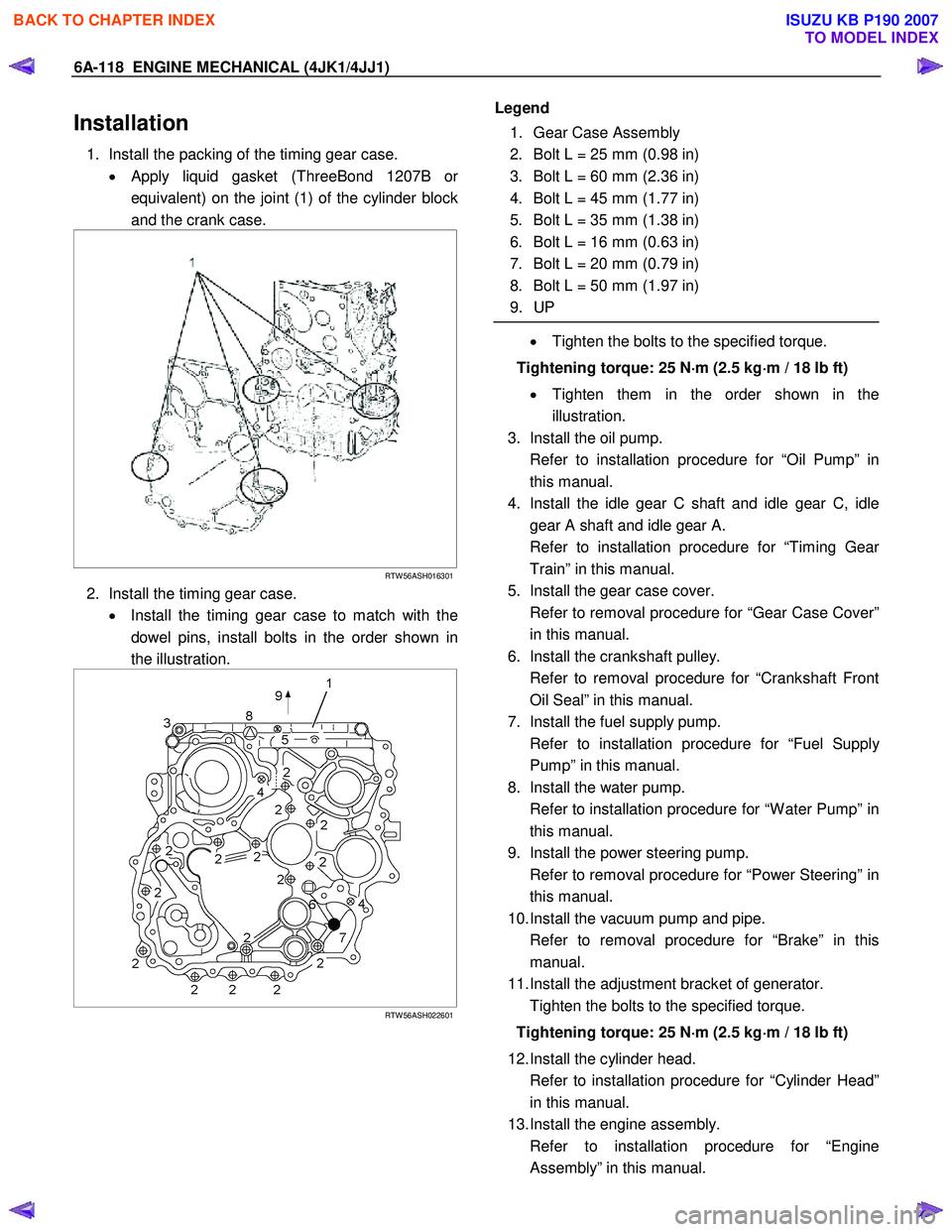
3. Install the connecting rod cap.
• Install the bearing on the connecting rod cap
and apply engine oil.
• Install the cap, matching the numbers (1, 2, 3,
and 4) of the caps and connecting rods.
015R100007
• Apply engine oil disulfide on the screw part and
the setting face of the tightening bolt and
tighten it with the designated torque.
Tightening torque: 1st step = 29 N ⋅
⋅⋅
⋅
m (3.0 kg ⋅
⋅⋅
⋅
m / 22 lb ft)
2nd step = 45° (degrees)
Special tool
Angle gauge: 5-8840-0266-0
Note:
Make sure that the crankshaft smoothly rotates.
BACK TO CHAPTER INDEX
TO MODEL INDEX
ISUZU KB P190 2007
Page 1469 of 6020
ENGINE MECHANICAL (4JK1/4JJ1) 6A-109
015LX130
4. Install the oil pan.
Refer to “Oil Pan”.
5. Install the gear case assembly.
Refer to “Gear Case Assembly”.
6. Install the cylinder head.
Refer to “Cylinder Head”.
7. Install the camshaft assembly.
Refer to “Camshaft Assembly”.
8. Install the cylinder head cover.
Refer to “Cylinder Head Cover”.
BACK TO CHAPTER INDEX
TO MODEL INDEX
ISUZU KB P190 2007
Page 1477 of 6020

ENGINE MECHANICAL (4JK1/4JJ1) 6A-117
Removal
1. Remove the engine assembly.
Refer to removal procedure for “Engine Assembly” in this manual.
2. Remove the cylinder head.
Refer to removal procedure for “Cylinder Head” in this manual.
3. Remove the adjustment bracket of generator.
4. Remove the vacuum pump and pipe.
Refer to removal procedure for “Brake” in this manual.
5. Remove the power steering pump.
Refer to removal procedure for “Power Steering” in this manual.
6. Remove the water pump.
Refer to removal procedure for “W ater Pump” in this manual.
7. Remove the fuel supply pump.
Refer to removal procedure for “Fuel Suppl
y
Pump” in this manual.
8. Remove the crankshaft pulley.
Refer to removal procedure for “Crankshaft Front Oil Seal” in this manual.
9. Remove the gear case cover.
Refer to removal procedure for “Gear Case Cover” in this manual.
10. Remove the idle gear A and idle gear A shaft, idle gear C and idle gear C shaft.
Refer to removal procedure for “Timing Gea
r
Train” in this manual.
RTW 56ASH011401
RTW 56ASH011301
11. Remove the oil pump.
Refer to removal procedure for “Oil Pump” in this manual.
12. Remove the timing gear case (1) and gasket (2).
RTW 76ASH001201
BACK TO CHAPTER INDEX
TO MODEL INDEX
ISUZU KB P190 2007
Page 1478 of 6020

6A-118 ENGINE MECHANICAL (4JK1/4JJ1)
Installation
1. Install the packing of the timing gear case.
• Apply liquid gasket (ThreeBond 1207B o
r
equivalent) on the joint (1) of the cylinder block
and the crank case.
RTW 56ASH016301
2. Install the timing gear case.
• Install the timing gear case to match with the
dowel pins, install bolts in the order shown in
the illustration.
RTW 56ASH022601
Legend
1. Gear Case Assembly
2. Bolt L = 25 mm (0.98 in)
3. Bolt L = 60 mm (2.36 in)
4. Bolt L = 45 mm (1.77 in)
5. Bolt L = 35 mm (1.38 in)
6. Bolt L = 16 mm (0.63 in)
7. Bolt L = 20 mm (0.79 in)
8. Bolt L = 50 mm (1.97 in)
9. UP
• Tighten the bolts to the specified torque.
Tightening torque: 25 N ⋅
⋅⋅
⋅
m (2.5 kg ⋅
⋅⋅
⋅
m / 18 lb ft)
• Tighten them in the order shown in the
illustration.
3. Install the oil pump.
Refer to installation procedure for “Oil Pump” in this manual.
4. Install the idle gear C shaft and idle gear C, idle gear A shaft and idle gear A.
Refer to installation procedure for “Timing Gea
r
Train” in this manual.
5. Install the gear case cover.
Refer to removal procedure for “Gear Case Cover” in this manual.
6. Install the crankshaft pulley.
Refer to removal procedure for “Crankshaft Front Oil Seal” in this manual.
7. Install the fuel supply pump.
Refer to installation procedure for “Fuel Suppl
y
Pump” in this manual.
8. Install the water pump.
Refer to installation procedure for “W ater Pump” in this manual.
9. Install the power steering pump.
Refer to removal procedure for “Power Steering” in this manual.
10. Install the vacuum pump and pipe.
Refer to removal procedure for “Brake” in this manual.
11. Install the adjustment bracket of generator.
Tighten the bolts to the specified torque.
Tightening torque: 25 N ⋅
⋅⋅
⋅
m (2.5 kg ⋅
⋅⋅
⋅
m / 18 lb ft)
12. Install the cylinder head.
Refer to installation procedure for “Cylinder Head” in this manual.
13. Install the engine assembly.
Refer to installation procedure for “Engine Assembly” in this manual.
BACK TO CHAPTER INDEX
TO MODEL INDEX
ISUZU KB P190 2007
Page 1480 of 6020
6A-120 ENGINE MECHANICAL (4JK1/4JJ1)
Crankshaft Front Oil Seal
Components
RTW 76AMF000501
Legend 1. Bolt
2. W asher 3. Crankshaft Damper Pulley
4. Crankshaft Front Oil Seal
Removal
1. Remove the fan assembly.
• Remove the fan assembly unscrewing fou
r
mounting nuts.
RTW 56ASH025401
2. Remove the fan belt.
BACK TO CHAPTER INDEX
TO MODEL INDEX
ISUZU KB P190 2007
Page 1481 of 6020

ENGINE MECHANICAL (4JK1/4JJ1) 6A-121
3. Remove the crankshaft pulley.
Note:
Do not reuse the bolt and the washer.
LNW 61ASH005301
4. Remove the crankshaft front oil seal.
• Remove only the oil seal with a screwdriver o
r
the like, avoiding damage to the oil seal contact
surface on the front cover and the shaft.
Installation
1. Install the crankshaft front oil seal. • Use the special tool to install the front oil seal.
Front Oil Seal
Installer: 5-8840-2821-0 (1)
RTW 56ASH016501
• Apply engine oil to the lip of the oil seal.
• W ith the seal pressed in check the dimension
of the oil seal section.
Standard Dimension = 1.5 mm (0.06 in)
RTW 56ASH016601
2. Install the crankshaft damper pulley.
• Install the crankshaft pulley aligning with the
key on the crankshaft.
• Hold the flywheel ring gear stationary to prevent
the crankshaft from turning when tightening the
damper pulley bolt.
Tightening torque: 294 N ⋅
⋅⋅
⋅
m (30 kg ⋅
⋅⋅
⋅
m/217 lb ft)
• Take care not to damage the crankshaft
damper pulley boss.
014R100014
3. Install the fan belt.
• Refer to “Engine Cooling”
BACK TO CHAPTER INDEX
TO MODEL INDEX
ISUZU KB P190 2007
Page 1482 of 6020
6A-122 ENGINE MECHANICAL (4JK1/4JJ1)
Torque Specifications
RTW 76AMF000601
Special Tools
ILLUSTRATION PART NO.
PART NAME
5-8840-2821-0
Oil seal installer
BACK TO CHAPTER INDEX
TO MODEL INDEX
ISUZU KB P190 2007
Page 1483 of 6020
ENGINE MECHANICAL (4JK1/4JJ1) 6A-123
Crankshaft Rear Oil Seal
Components
RTW 56ALF002501
Legend 1. Crankshaft Rear Oil Seal
2. Flywheel
3. Driven Plate 4. Clutch Pressure Plate
5. Transmission Assembly
BACK TO CHAPTER INDEX
TO MODEL INDEX
ISUZU KB P190 2007