2007 ISUZU KB P190 heater
[x] Cancel search: heaterPage 3270 of 6020
Engine Management – V6 – General Information Page 6C1-1–28
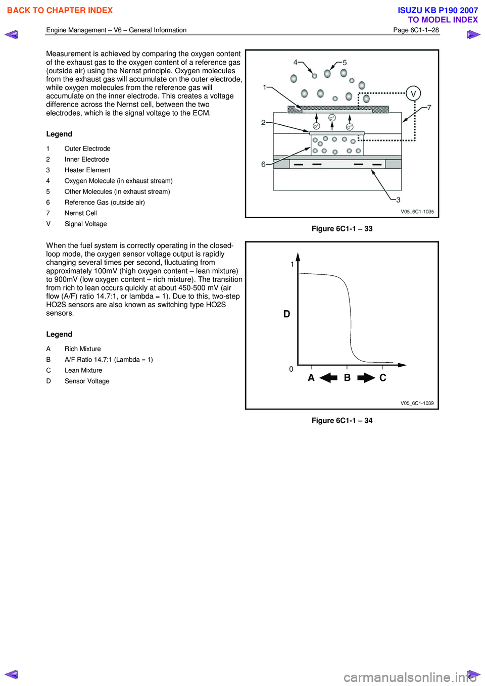
Measurement is achieved by comparing the oxygen content
of the exhaust gas to the oxygen content of a reference gas
(outside air) using the Nernst principle. Oxygen molecules
from the exhaust gas will accumulate on the outer electrode,
while oxygen molecules from the reference gas will
accumulate on the inner electrode. This creates a voltage
difference across the Nernst cell, between the two
electrodes, which is the signal voltage to the ECM.
Legend
1 Outer Electrode
2 Inner Electrode
3 Heater Element
4 Oxygen Molecule (in exhaust stream)
5 Other Molecules (in exhaust stream)
6 Reference Gas (outside air)
7 Nernst Cell
V Signal Voltage
Figure 6C1-1 – 33
W hen the fuel system is correctly operating in the closed-
loop mode, the oxygen sensor voltage output is rapidly
changing several times per second, fluctuating from
approximately 100mV (high oxygen content – lean mixture)
to 900mV (low oxygen content – rich mixture). The transition
from rich to lean occurs quickly at about 450-500 mV (air
flow (A/F) ratio 14.7:1, or lambda = 1). Due to this, two-step
HO2S sensors are also known as switching type HO2S
sensors.
Legend
A Rich Mixture
B A/F Ratio 14.7:1 (Lambda = 1)
C Lean Mixture
D Sensor Voltage
Figure 6C1-1 – 34
BACK TO CHAPTER INDEX
TO MODEL INDEX
ISUZU KB P190 2007
Page 3271 of 6020
Engine Management – V6 – General Information Page 6C1-1–29
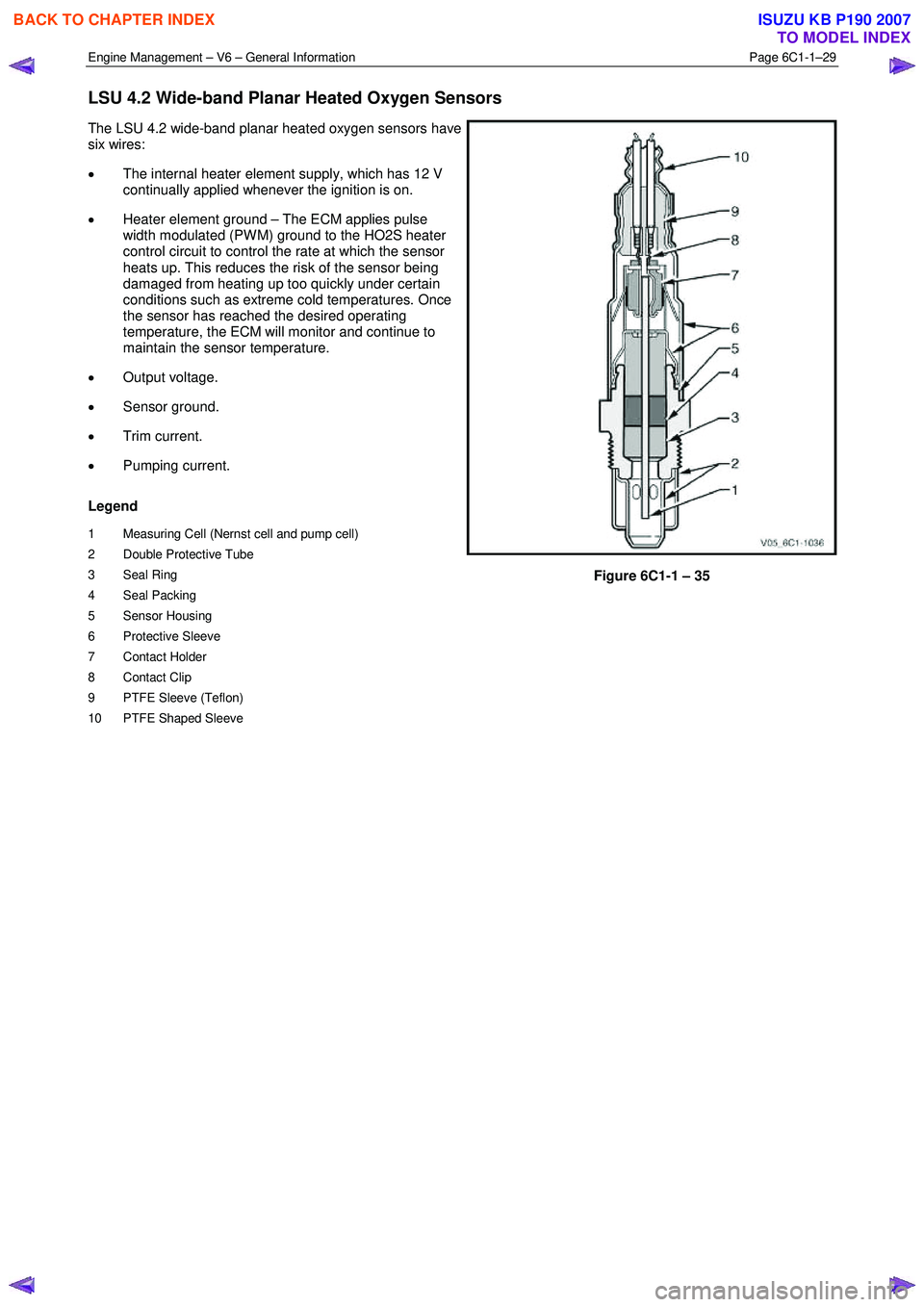
LSU 4.2 Wide-band Planar Heated Oxygen Sensors
The LSU 4.2 wide-band planar heated oxygen sensors have
six wires:
• The internal heater element supply, which has 12 V
continually applied whenever the ignition is on.
• Heater element ground – The ECM applies pulse
width modulated (PW M) ground to the HO2S heater
control circuit to control the rate at which the sensor
heats up. This reduces the risk of the sensor being
damaged from heating up too quickly under certain
conditions such as extreme cold temperatures. Once
the sensor has reached the desired operating
temperature, the ECM will monitor and continue to
maintain the sensor temperature.
• Output voltage.
• Sensor ground.
• Trim current.
• Pumping current.
Legend
1 Measuring Cell (Nernst cell and pump cell)
2 Double Protective Tube
3 Seal Ring
4 Seal Packing
5 Sensor Housing
6 Protective Sleeve
7 Contact Holder
8 Contact Clip
9 PTFE Sleeve (Teflon)
10 PTFE Shaped Sleeve
Figure 6C1-1 – 35
BACK TO CHAPTER INDEX
TO MODEL INDEX
ISUZU KB P190 2007
Page 3272 of 6020
Engine Management – V6 – General Information Page 6C1-1–30
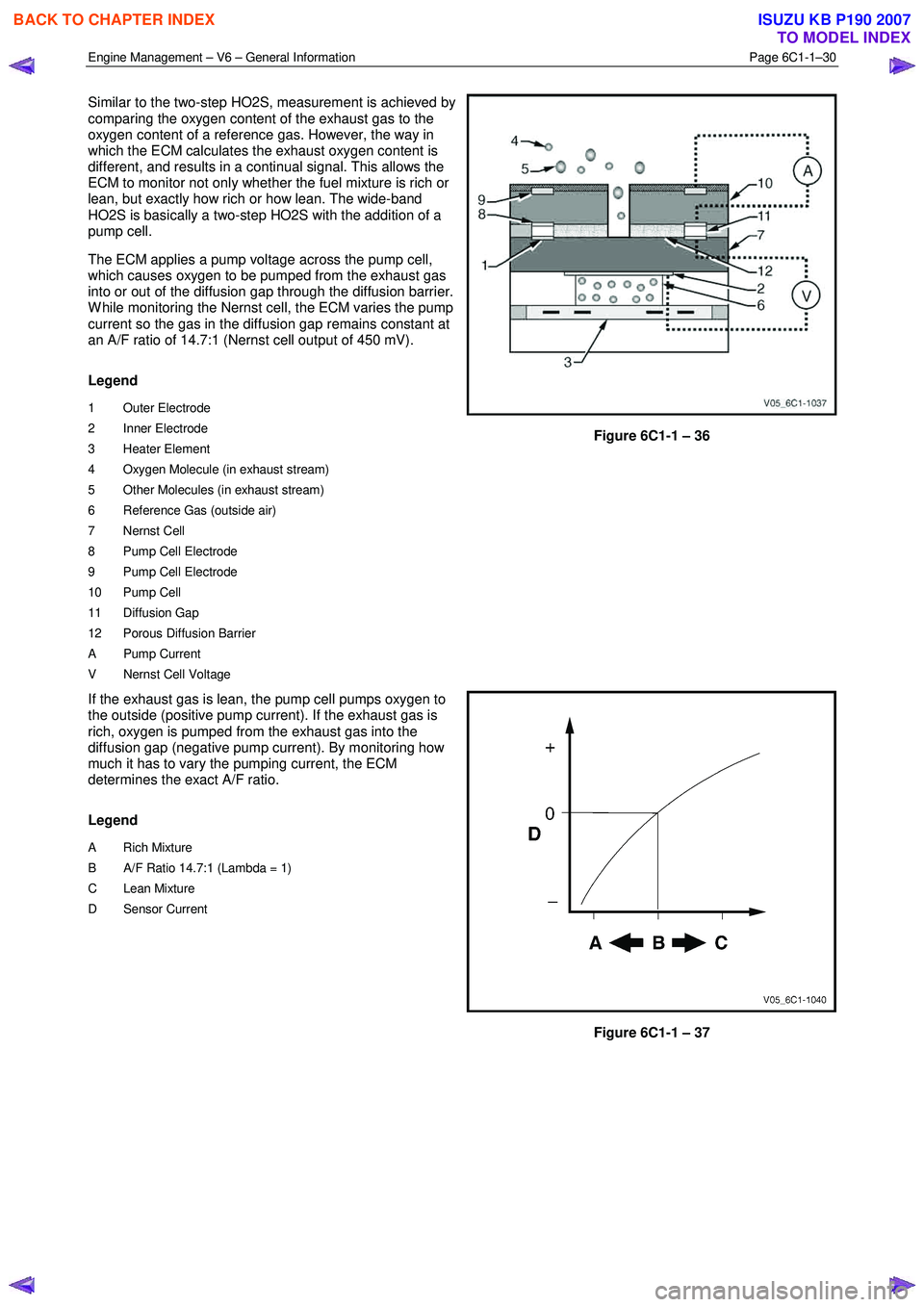
Similar to the two-step HO2S, measurement is achieved by
comparing the oxygen content of the exhaust gas to the
oxygen content of a reference gas. However, the way in
which the ECM calculates the exhaust oxygen content is
different, and results in a continual signal. This allows the
ECM to monitor not only whether the fuel mixture is rich or
lean, but exactly how rich or how lean. The wide-band
HO2S is basically a two-step HO2S with the addition of a
pump cell.
The ECM applies a pump voltage across the pump cell,
which causes oxygen to be pumped from the exhaust gas
into or out of the diffusion gap through the diffusion barrier.
W hile monitoring the Nernst cell, the ECM varies the pump
current so the gas in the diffusion gap remains constant at
an A/F ratio of 14.7:1 (Nernst cell output of 450 mV).
Legend
1 Outer Electrode
2 Inner Electrode
3 Heater Element
4 Oxygen Molecule (in exhaust stream)
5 Other Molecules (in exhaust stream)
6 Reference Gas (outside air)
7 Nernst Cell
8 Pump Cell Electrode
9 Pump Cell Electrode
10 Pump Cell
11 Diffusion Gap
12 Porous Diffusion Barrier
A Pump Current
V Nernst Cell Voltage
Figure 6C1-1 – 36
If the exhaust gas is lean, the pump cell pumps oxygen to
the outside (positive pump current). If the exhaust gas is
rich, oxygen is pumped from the exhaust gas into the
diffusion gap (negative pump current). By monitoring how
much it has to vary the pumping current, the ECM
determines the exact A/F ratio.
Legend
A Rich Mixture
B A/F Ratio 14.7:1 (Lambda = 1)
C Lean Mixture
D Sensor Current
Figure 6C1-1 – 37
BACK TO CHAPTER INDEX
TO MODEL INDEX
ISUZU KB P190 2007
Page 3276 of 6020
Engine Management – V6 – General Information Page 6C1-1–34
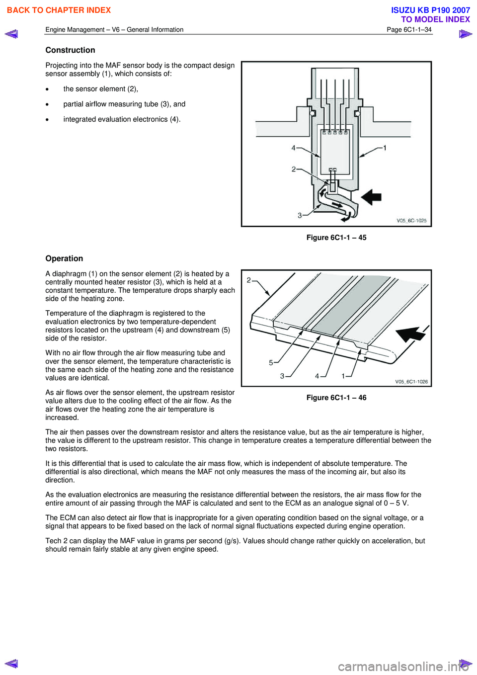
Construction
Projecting into the MAF sensor body is the compact design
sensor assembly (1), which consists of:
• the sensor element (2),
• partial airflow measuring tube (3), and
• integrated evaluation electronics (4).
Figure 6C1-1 – 45
Operation
A diaphragm (1) on the sensor element (2) is heated by a
centrally mounted heater resistor (3), which is held at a
constant temperature. The temperature drops sharply each
side of the heating zone.
Temperature of the diaphragm is registered to the
evaluation electronics by two temperature-dependent
resistors located on the upstream (4) and downstream (5)
side of the resistor.
W ith no air flow through the air flow measuring tube and
over the sensor element, the temperature characteristic is
the same each side of the heating zone and the resistance
values are identical.
As air flows over the sensor element, the upstream resistor
value alters due to the cooling effect of the air flow. As the
air flows over the heating zone the air temperature is
increased.
Figure 6C1-1 – 46
The air then passes over the downstream resistor and alters the resistance value, but as the air temperature is higher,
the value is different to the upstream resistor. This change in temperature creates a temperature differential between the
two resistors.
It is this differential that is used to calculate the air mass flow, which is independent of absolute temperature. The
differential is also directional, which means the MAF not only measures the mass of the incoming air, but also its
direction.
As the evaluation electronics are measuring the resistance differential between the resistors, the air mass flow for the
entire amount of air passing through the MAF is calculated and sent to the ECM as an analogue signal of 0 – 5 V.
The ECM can also detect air flow that is inappropriate for a given operating condition based on the signal voltage, or a
signal that appears to be fixed based on the lack of normal signal fluctuations expected during engine operation.
Tech 2 can display the MAF value in grams per second (g/s). Values should change rather quickly on acceleration, but
should remain fairly stable at any given engine speed.
BACK TO CHAPTER INDEX
TO MODEL INDEX
ISUZU KB P190 2007
Page 3290 of 6020
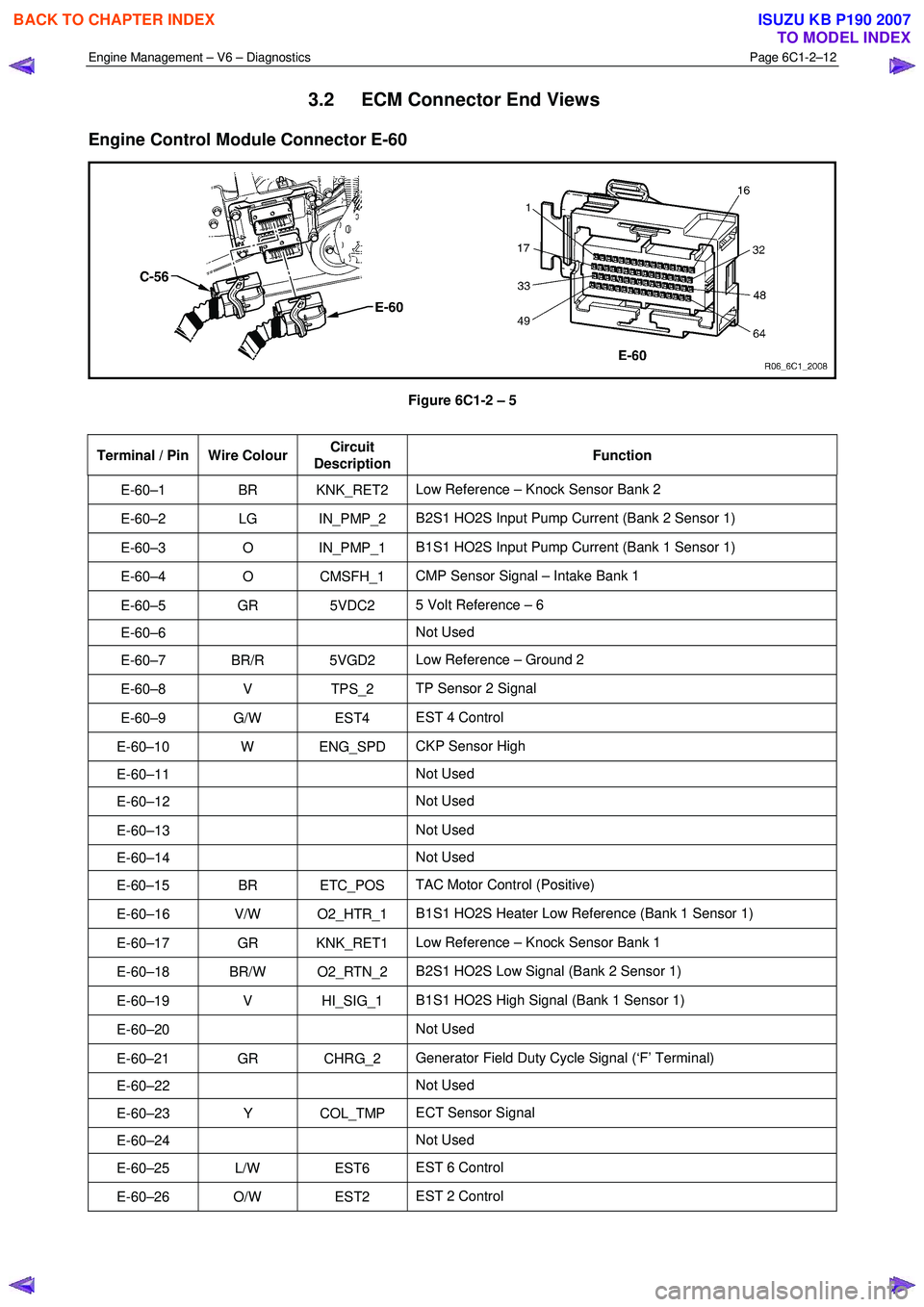
Engine Management – V6 – Diagnostics Page 6C1-2–12
3.2 ECM Connector End Views
Engine Control Module Connector E-60
Figure 6C1-2 – 5
Terminal / Pin Wire Colour Circuit
Description Function
E-60–1 BR KNK_RET2
Low Reference – Knock Sensor Bank 2
E-60–2 LG IN_PMP_2 B2S1 HO2S Input Pump Current (Bank 2 Sensor 1)
E-60–3 O IN_PMP_1 B1S1 HO2S Input Pump Current (Bank 1 Sensor 1)
E-60–4 O CMSFH_1 CMP Sensor Signal – Intake Bank 1
E-60–5 GR 5VDC2 5 Volt Reference – 6
E-60–6 Not Used
E-60–7 BR/R 5VGD2 Low Reference – Ground 2
E-60–8 V TPS_2 TP Sensor 2 Signal
E-60–9 G/W EST4 EST 4 Control
E-60–10 W ENG_SPD CKP Sensor High
E-60–11 Not Used
E-60–12 Not Used
E-60–13 Not Used
E-60–14 Not Used
E-60–15 BR ETC_POS TAC Motor Control (Positive)
E-60–16 V/W O2_HTR_1 B1S1 HO2S Heater Low Reference (Bank 1 Sensor 1)
E-60–17 GR KNK_RET1 Low Reference – Knock Sensor Bank 1
E-60–18 BR/W O2_RTN_2 B2S1 HO2S Low Signal (Bank 2 Sensor 1)
E-60–19 V HI_SIG_1 B1S1 HO2S High Signal (Bank 1 Sensor 1)
E-60–20 Not Used
E-60–21 GR CHRG_2 Generator Field Duty Cycle Signal (‘F’ Terminal)
E-60–22 Not Used
E-60–23 Y COL_TMP ECT Sensor Signal
E-60–24 Not Used
E-60–25 L/W EST6 EST 6 Control
E-60–26 O/W EST2 EST 2 Control
BACK TO CHAPTER INDEX
TO MODEL INDEX
ISUZU KB P190 2007
Page 3291 of 6020
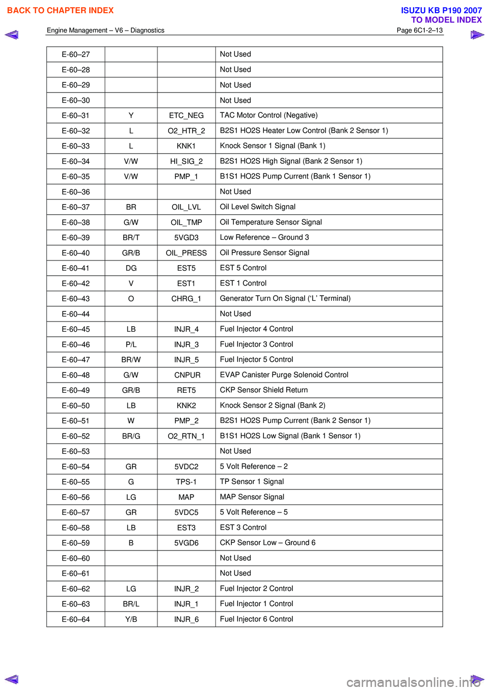
Engine Management – V6 – Diagnostics Page 6C1-2–13
E-60–27 Not Used
E-60–28 Not Used
E-60–29 Not
Used
E-60–30 Not Used
E-60–31 Y ETC_NEG TAC Motor Control (Negative)
E-60–32 L O2_HTR_2 B2S1 HO2S Heater Low Control (Bank 2 Sensor 1)
E-60–33 L KNK1 Knock Sensor 1 Signal (Bank 1)
E-60–34 V/W HI_SIG_2 B2S1 HO2S High Signal (Bank 2 Sensor 1)
E-60–35 V/W PMP_1 B1S1 HO2S Pump Current (Bank 1 Sensor 1)
E-60–36 Not Used
E-60–37 BR OIL_LVL Oil Level Switch Signal
E-60–38 G/W OIL_TMP Oil Temperature Sensor Signal
E-60–39 BR/T 5VGD3 Low Reference – Ground 3
E-60–40 GR/B OIL_PRESS Oil Pressure Sensor Signal
E-60–41 DG EST5 EST 5 Control
E-60–42 V EST1 EST 1 Control
E-60–43 O CHRG_1 Generator Turn On Signal (‘L’ Terminal)
E-60–44 Not Used
E-60–45 LB INJR_4 Fuel Injector 4 Control
E-60–46 P/L INJR_3 Fuel Injector 3 Control
E-60–47 BR/W INJR_5 Fuel Injector 5 Control
E-60–48 G/W CNPUR EVAP Canister Purge Solenoid Control
E-60–49 GR/B RET5 CKP Sensor Shield Return
E-60–50 LB KNK2 Knock Sensor 2 Signal (Bank 2)
E-60–51 W PMP_2 B2S1 HO2S Pump Current (Bank 2 Sensor 1)
E-60–52 BR/G O2_RTN_1 B1S1 HO2S Low Signal (Bank 1 Sensor 1)
E-60–53 Not Used
E-60–54 GR 5VDC2 5 Volt Reference – 2
E-60–55 G TPS-1 TP Sensor 1 Signal
E-60–56 LG MAP MAP Sensor Signal
E-60–57 GR 5VDC5 5 Volt Reference – 5
E-60–58 LB EST3 EST 3 Control
E-60–59 B 5VGD6 CKP Sensor Low – Ground 6
E-60–60 Not Used
E-60–61 Not Used
E-60–62 LG INJR_2 Fuel Injector 2 Control
E-60–63 BR/L INJR_1 Fuel Injector 1 Control
E-60–64 Y/B INJR_6 Fuel Injector 6 Control
BACK TO CHAPTER INDEX
TO MODEL INDEX
ISUZU KB P190 2007
Page 3292 of 6020
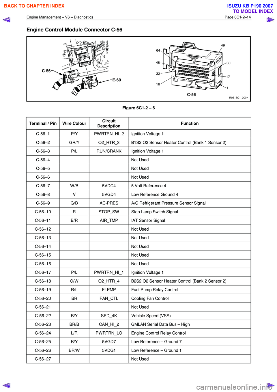
Engine Management – V6 – Diagnostics Page 6C1-2–14
Engine Control Module Connector C-56
Figure 6C1-2 – 6
Terminal / Pin Wire Colour Circuit
Description Function
C-56–1 P/Y PW RTRN_HI_2 Ignition Voltage 1
C-56–2 GR/Y O2_HTR_3 B1S2 O2 Sensor Heater Control (Bank 1 Sensor 2)
C-56–3 P/L RUN/CRANK Ignition Voltage 1
C-56–4 Not
Used
C-56–5 Not Used
C-56–6 Not Used
C-56–7 W /B 5VDC4 5 Volt Reference 4
C-56–8 V 5VGD4 Low Reference Ground 4
C-56–9 G/B AC-PRES A/C Refrigerant Pressure Sensor Signal
C-56–10 R STOP_SW Stop Lamp Switch Signal
C-56–11 B/R AIR_TMP IAT Sensor Signal
C-56–12 Not Used
C-56–13 Not Used
C-56–14 Not Used
C-56–15 Not Used
C-56–16 Not Used
C-56–17 P/L PW RTRN_HI_1 Ignition Voltage 1
C-56–18 O/W O2_HTR_4 B2S2 O2 Sensor Heater Control (Bank 2 Sensor 2)
C-56–19 R/L FLPMP Fuel Pump Relay Control
C-56–20 BR FAN_CTL Cooling Fan Control
C-56–21 Not Used
C-56–22 B/Y SPD_4K Vehicle Speed (VSS)
C-56–23 BR/B CAN_HI_2 GMLAN Serial Data Bus – High
C-56–24 L/R PW RTRN_LO Engine Control Relay Control
C-56–25 B/Y 5VGD7 Low Reference – Ground 7
C-56–26 BR/W 5VDG1 Low Reference – Ground 1
C-56–27 Not Used
BACK TO CHAPTER INDEX
TO MODEL INDEX
ISUZU KB P190 2007
Page 3314 of 6020
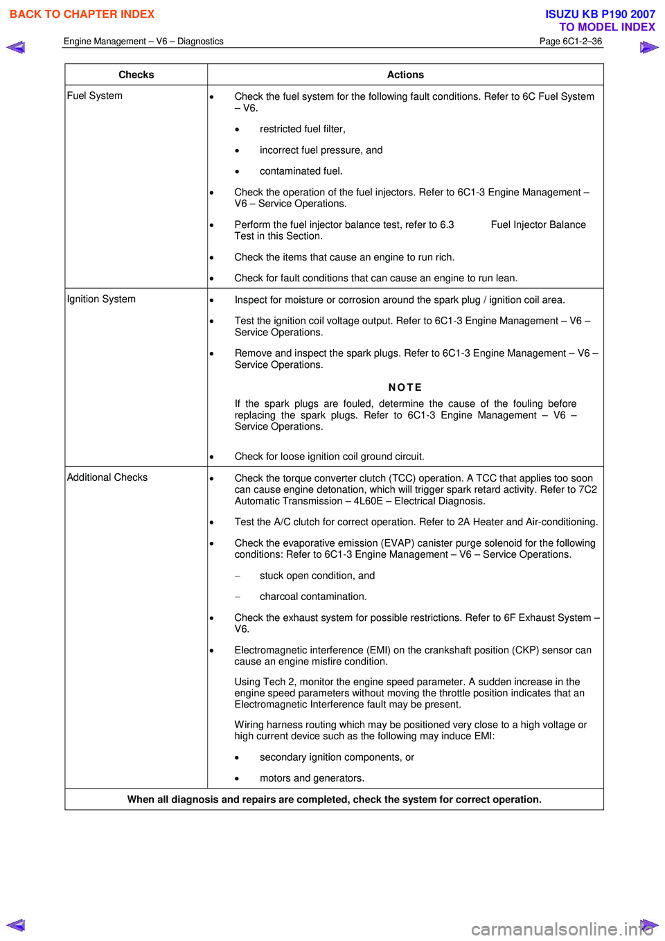
Engine Management – V6 – Diagnostics Page 6C1-2–36
Checks Actions
Fuel System
• Check the fuel system for the following fault conditions. Refer to 6C Fuel System
– V6.
• restricted fuel filter,
• incorrect fuel pressure, and
• contaminated fuel.
• Check the operation of the fuel injectors. Refer to 6C1-3 Engine Management –
V6 – Service Operations.
• Perform the fuel injector balance test, refer to 6.3 Fuel Injector Balance
Test in this Section.
• Check the items that cause an engine to run rich.
• Check for fault conditions that can cause an engine to run lean.
Ignition System
• Inspect for moisture or corrosion around the spark plug / ignition coil area.
• Test the ignition coil voltage output. Refer to 6C1-3 Engine Management – V6 –
Service Operations.
• Remove and inspect the spark plugs. Refer to 6C1-3 Engine Management – V6 –
Service Operations.
NOTE
If the spark plugs are fouled, determine the cause of the fouling before
replacing the spark plugs. Refer to 6C1-3 Engine Management – V6 –
Service Operations.
• Check for loose ignition coil ground circuit.
Additional Checks
• Check the torque converter clutch (TCC) operation. A TCC that applies too soon
can cause engine detonation, which will trigger spark retard activity. Refer to 7C2
Automatic Transmission – 4L60E – Electrical Diagnosis.
• Test the A/C clutch for correct operation. Refer to 2A Heater and Air-conditioning.
• Check the evaporative emission (EVAP) canister purge solenoid for the following
conditions: Refer to 6C1-3 Engine Management – V6 – Service Operations.
− stuck open condition, and
− charcoal contamination.
• Check the exhaust system for possible restrictions. Refer to 6F Exhaust System –
V6.
• Electromagnetic interference (EMI) on the crankshaft position (CKP) sensor can
cause an engine misfire condition.
Using Tech 2, monitor the engine speed parameter. A sudden increase in the engine speed parameters without moving the throttle position indicates that an
Electromagnetic Interference fault may be present.
W iring harness routing which may be positioned very close to a high voltage or high current device such as the following may induce EMI:
• secondary ignition components, or
• motors and generators.
When all diagnosis and repairs are completed, check the system for correct operation.
BACK TO CHAPTER INDEX
TO MODEL INDEX
ISUZU KB P190 2007