Page 2335 of 6020
ENGINE DRIVEABILITY AND EMISSIONS 6E–165
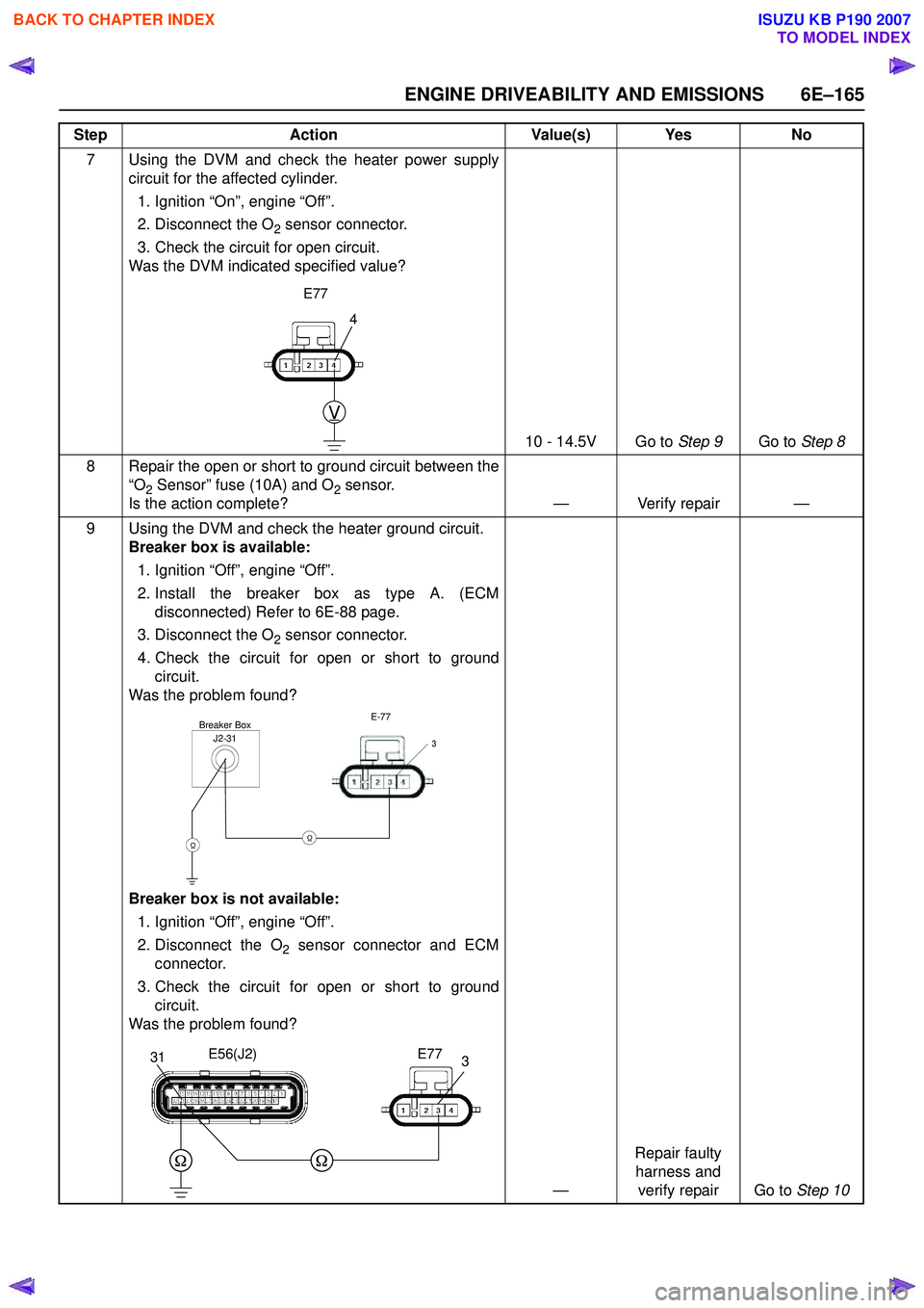
7 Using the DVM and check the heater power supplycircuit for the affected cylinder.
1. Ignition “On”, engine “Off”.
2. Disconnect the O
2 sensor connector.
3. Check the circuit for open circuit.
Was the DVM indicated specified value?
10 - 14.5V Go to Step 9Go to Step 8
8 Repair the open or short to ground circuit between the “O
2 Sensor” fuse (10A) and O2 sensor.
Is the action complete? — Verify repair —
9 Using the DVM and check the heater ground circuit. Breaker box is available:
1. Ignition “Off”, engine “Off”.
2. Install the breaker box as type A. (ECM disconnected) Refer to 6E-88 page.
3. Disconnect the O
2 sensor connector.
4. Check the circuit for open or short to ground circuit.
Was the problem found?
Breaker box is not available:
1. Ignition “Off”, engine “Off”.
2. Disconnect the O
2 sensor connector and ECM
connector.
3. Check the circuit for open or short to ground circuit.
Was the problem found?
—Repair faulty
harness and verify repair Go to Step 10
Step
Action Value(s) Yes No
4
V
E77
J2-31Breaker BoxE-77
3
ΩΩ
331E56(J2)E77
BACK TO CHAPTER INDEX
TO MODEL INDEX
ISUZU KB P190 2007
Page 2336 of 6020
6E–166 ENGINE DRIVEABILITY AND EMISSIONS
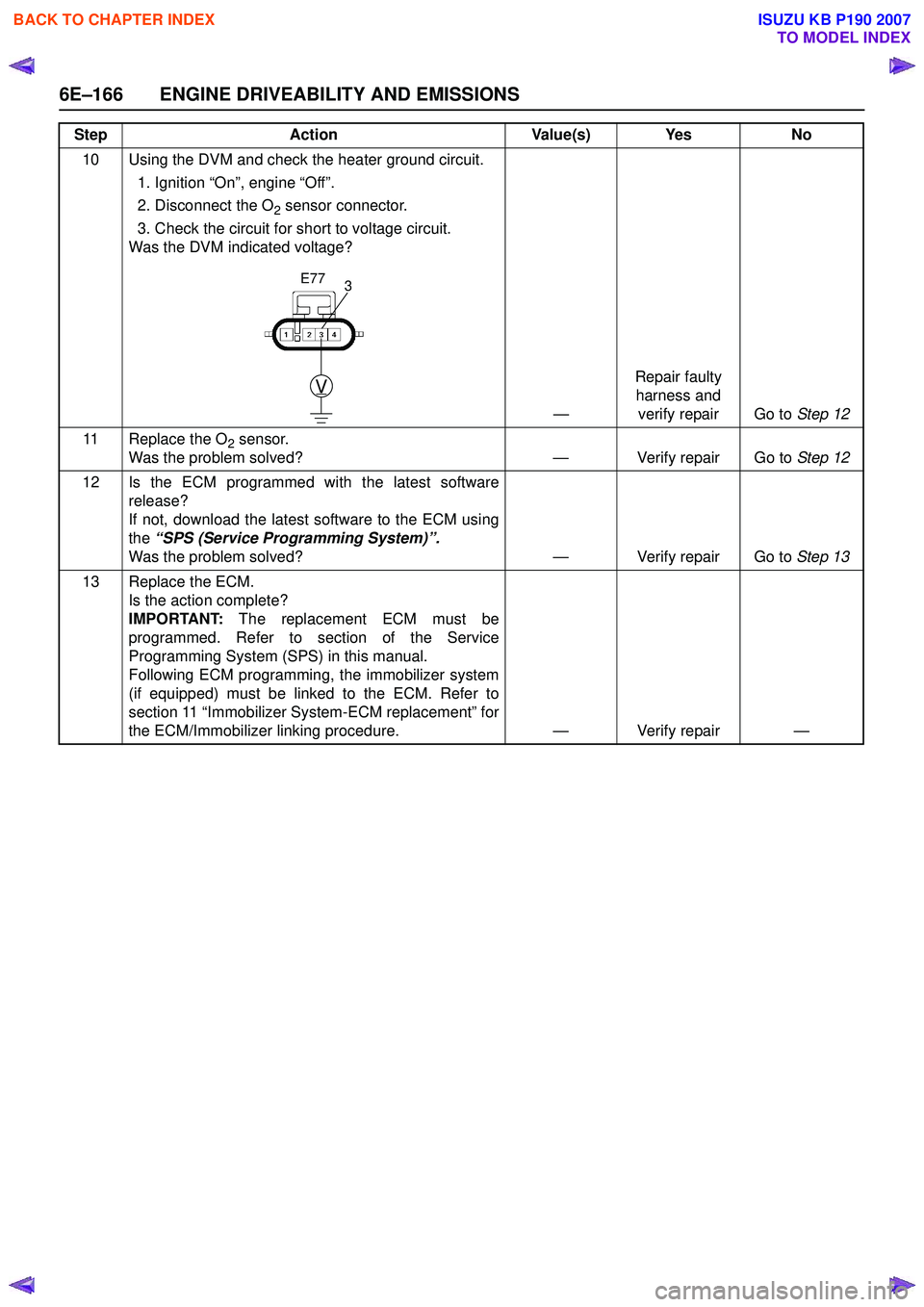
10 Using the DVM and check the heater ground circuit.1. Ignition “On”, engine “Off”.
2. Disconnect the O
2 sensor connector.
3. Check the circuit for short to voltage circuit.
Was the DVM indicated voltage?
—Repair faulty
harness and verify repair Go to Step 12
11 Replace the O
2 sensor.
Was the problem solved? — Verify repair Go to Step 12
12 Is the ECM programmed with the latest software release?
If not, download the latest software to the ECM using
the “SPS (Service Programming System)”.
Was the problem solved? — Verify repair Go to Step 13
13 Replace the ECM. Is the action complete?
IMPORTANT: The replacement ECM must be
programmed. Refer to section of the Service
Programming System (SPS) in this manual.
Following ECM programming, the immobilizer system
(if equipped) must be linked to the ECM. Refer to
section 11 “Immobilizer System-ECM replacement” for
the ECM/Immobilizer linking procedure. — Verify repair —
Step
Action Value(s) Yes No
3
V
E77
BACK TO CHAPTER INDEX
TO MODEL INDEX
ISUZU KB P190 2007
Page 2640 of 6020
Engine Mechanical – V6 Page 6A1–161
Reinstall
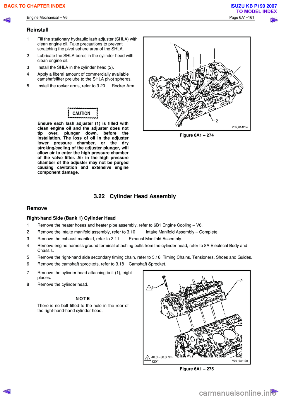
1 Fill the stationary hydraulic lash adjuster (SHLA) with
clean engine oil. Take precautions to prevent
scratching the pivot sphere area of the SHLA.
2 Lubricate the SHLA bores in the cylinder head with clean engine oil.
3 Install the SHLA in the cylinder head (2).
4 Apply a liberal amount of commercially available camshaft/lifter prelube to the SHLA pivot spheres.
5 Install the rocker arms, refer to 3.20 Rocker Arm.
CAUTION
Ensure each lash adjuster (1) is filled with
clean engine oil and the adjuster does not
tip over, plunger down, before the
installation. The loss of oil in the adjuster
lower pressure chamber, or the dry
stroking/cycling of the adjuster plunger, will
allow air to enter the high pressure chamber
of the valve lifter. Air in the high pressure
chamber of the adjuster may not be purged
causing cavitation and extensive engine
component damage.
Figure 6A1 – 274
3.22 Cylinder Head Assembly
Remove
Right-hand Side (Bank 1) Cylinder Head
1 Remove the heater hoses and heater pipe assembly, refer to 6B1 Engine Cooling – V6.
2 Remove the intake manifold assembly, refer to 3.10 Intake Manifold Assembly – Complete.
3 Remove the exhaust manifold, refer to 3.11 Exhaust Manifold Assembly.
4 Remove engine harness ground terminal attaching bolts from the cylinder head, refer to 8A Electrical Body and Chassis.
5 Remove the right-hand side secondary timing chain, refer to 3.16 Timing Chains, Tensioners, Shoes and Guides.
6 Remove the camshaft sprockets, refer to 3.18 Camshaft Sprocket.
7 Remove the cylinder head attaching bolt (1), eight places.
8 Remove the cylinder head.
NOTE
There is no bolt fitted to the hole in the rear of
the right-hand-hand cylinder head.
Figure 6A1 – 275
BACK TO CHAPTER INDEX
TO MODEL INDEX
ISUZU KB P190 2007
Page 2667 of 6020
Engine Mechanical – V6 Page 6A1–188
22 Disconnect the EVAP valve outlet tube, (1) from the
upper intake manifold (2).
23 Remove the four long bolts, (3) attaching the upper intake manifold, (2) to the cylinder heads and lower
intake manifold.
Figure 6A1 – 324
23 Remove the six bolts, (1) attaching the lower intake manifold (2), then remove the manifold from the
engine.
24 Remove the following from the engine and engine compartment :
• Lower intake manifold to cylinder head gasket
• The Heater hose
• The Air Cleaner assembly
Figure 6A1 – 325
25 Remove the transmission support (1).
26 Remove the front and rear propeller shafts, (4W D Only), refer to 4C1 Front W heel Drive and 4C2 Drive
Line (For 4W D Vehicles).
27 Remove the front torsion bar springs, refer to 3C Suspension.
Figure 6A1 – 326
BACK TO CHAPTER INDEX
TO MODEL INDEX
ISUZU KB P190 2007
Page 2676 of 6020
Engine Mechanical – V6 Page 6A1–197
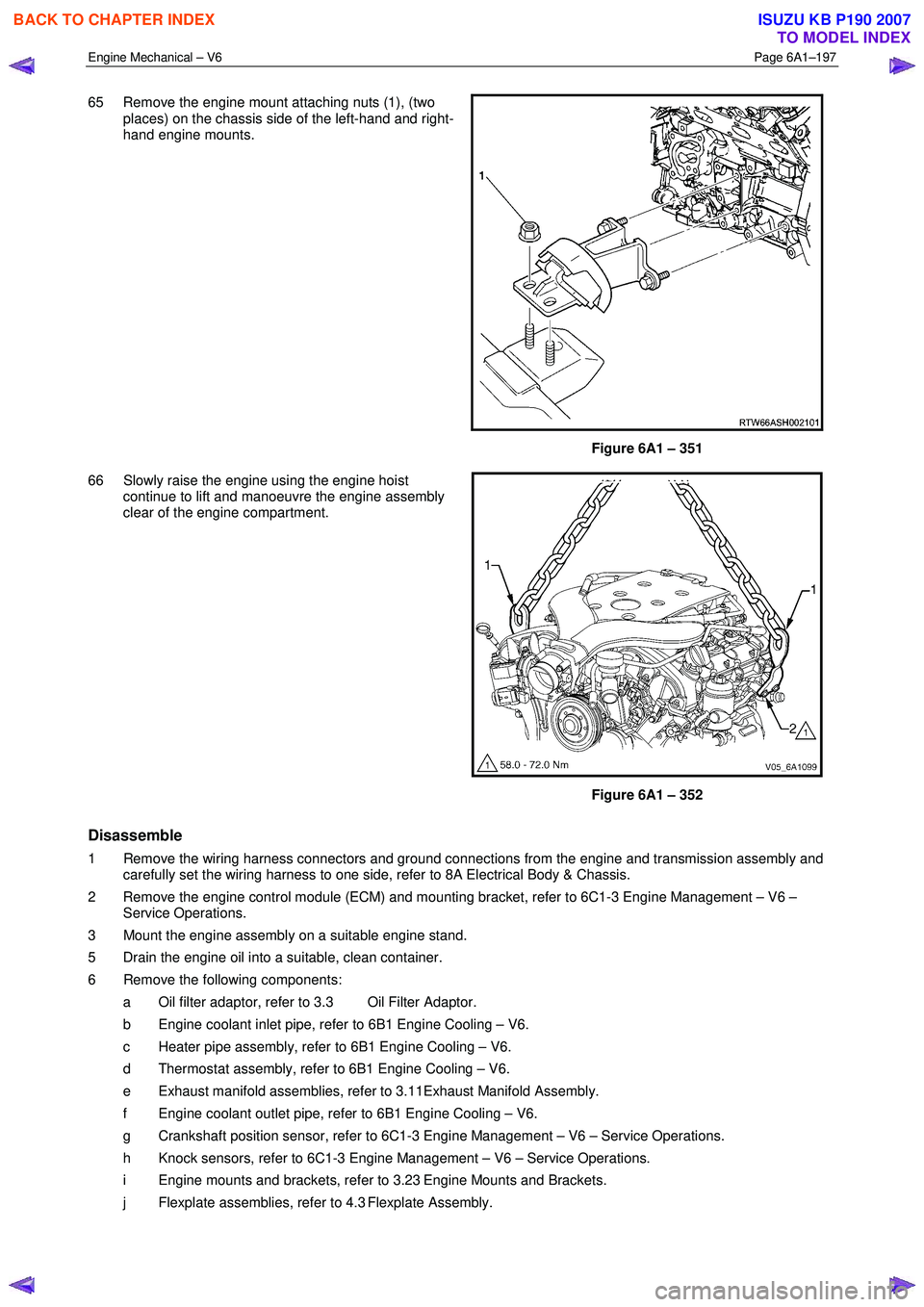
65 Remove the engine mount attaching nuts (1), (two
places) on the chassis side of the left-hand and right-
hand engine mounts.
Figure 6A1 – 351
66 Slowly raise the engine using the engine hoist continue to lift and manoeuvre the engine assembly
clear of the engine compartment.
Figure 6A1 – 352
Disassemble
1 Remove the wiring harness connectors and ground connections from the engine and transmission assembly and carefully set the wiring harness to one side, refer to 8A Electrical Body & Chassis.
2 Remove the engine control module (ECM) and mounting bracket, refer to 6C1-3 Engine Management – V6 – Service Operations.
3 Mount the engine assembly on a suitable engine stand.
5 Drain the engine oil into a suitable, clean container.
6 Remove the following components: a Oil filter adaptor, refer to 3.3 Oil Filter Adaptor.
b Engine coolant inlet pipe, refer to 6B1 Engine Cooling – V6.
c Heater pipe assembly, refer to 6B1 Engine Cooling – V6.
d Thermostat assembly, refer to 6B1 Engine Cooling – V6.
e Exhaust manifold assemblies, refer to 3.11Exhaust Manifold Assembly.
f Engine coolant outlet pipe, refer to 6B1 Engine Cooling – V6.
g Crankshaft position sensor, refer to 6C1-3 Engine Management – V6 – Service Operations.
h Knock sensors, refer to 6C1-3 Engine Management – V6 – Service Operations.
i Engine mounts and brackets, refer to 3.23 Engine Mounts and Brackets.
j Flexplate assemblies, refer to 4.3 Flexplate Assembly.
BACK TO CHAPTER INDEX
TO MODEL INDEX
ISUZU KB P190 2007
Page 2994 of 6020
Engine Mechanical – V6 Page 6A1–217
Page 6A1–217
3.23 Cylinder Head Assembly
Remove
Right-hand Side (Bank 1) Cylinder Head
1 Remove the heater hoses and heater pipe assembly, refer to Section 6B1 Engine Cooling – V6.
2 Remove the intake mani fold assembly, refer to 3.10 Intake Manifold Assembly – Complete .
3 Remove the exhaust manifold, refer to 3.11 Exhaust Manifold Assembly.
4 Remove engine harness ground terminal attaching bolts from the cylinder head, refer to
Section 8A Electrical Body and Chassis .
5 Remove the right-hand side secondary timing chain, refer to 3.16 Timing Chains, Tensioners, Shoes and Guides.
6 Remove the camshaft sprockets, refer to 3.18 Camshaft Sprocket .
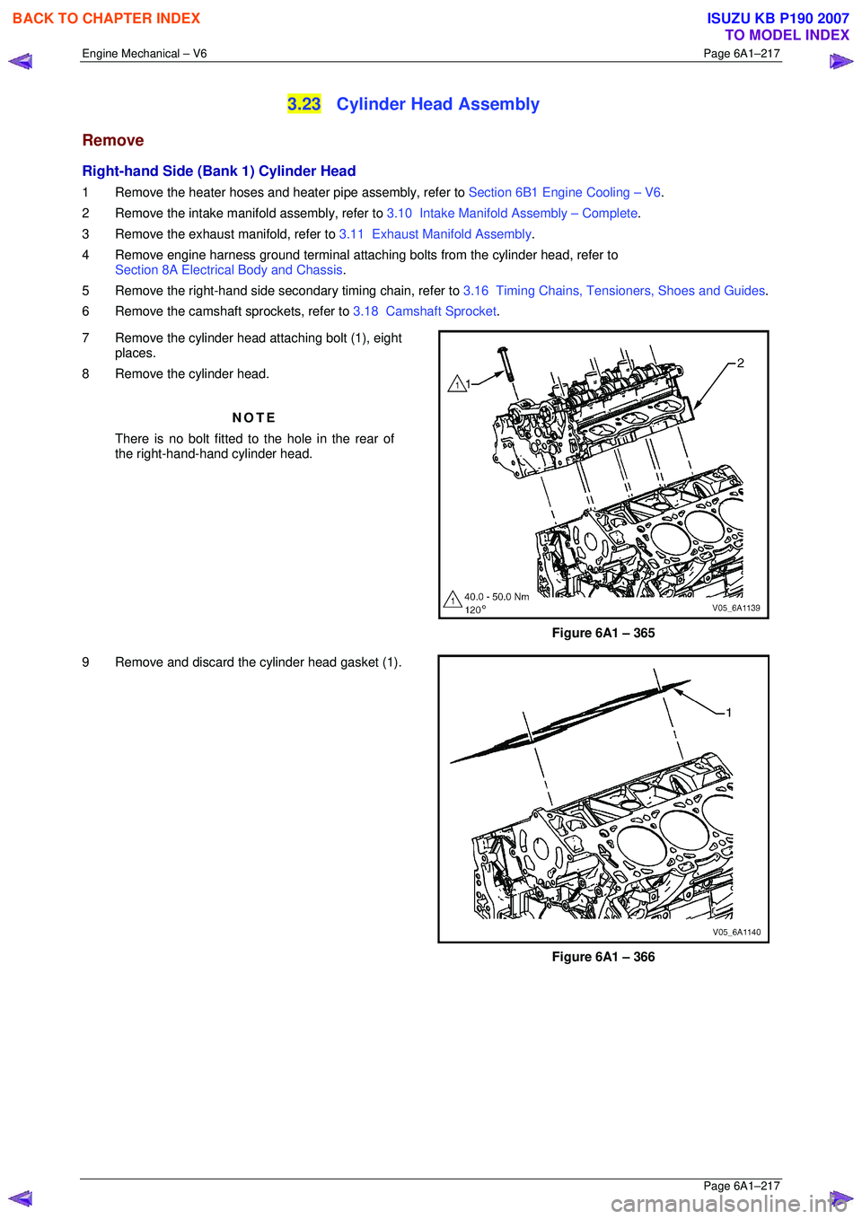
7 Remove the cylinder head attaching bolt (1), eight places.
8 Remove the cylinder head.
NOTE
There is no bolt fitted to the hole in the rear of
the right-hand-hand cylinder head.
Figure 6A1 – 365
9 Remove and discard the cylinder head gasket (1).
Figure 6A1 – 366
BACK TO CHAPTER INDEX
TO MODEL INDEX
ISUZU KB P190 2007
Page 3020 of 6020
Engine Mechanical – V6 Page 6A1–243
Page 6A1–243
22 Disconnect the EVAP valve outlet tube, (1) from the
upper intake manifold (2).
23 Remove the four long bolts, (3) attaching the upper intake manifold, (2) to the cylinder heads and lower
intake manifold.
Figure 6A1 – 414
23 Remove the six bolts, (1) attaching the lower intake manifold (2), then remove the manifold from the
engine.
24 Remove the following from the engine and engine compartment :
• Lower intake manifold to cylinder head gasket
• The Heater hose
• The Air Cleaner assembly
Figure 6A1 – 415
25 Remove the transmission support (1).
26 Remove the front and rear propeller shafts, (4WD Only), refer to Section 4C1 Front Wheel Drive and
Section 4C2 Drive Line (For 4WD Vehicles).
27 Remove the front torsion bar springs, refer to Section 3C Suspension .
Figure 6A1 – 416
BACK TO CHAPTER INDEX
TO MODEL INDEX
ISUZU KB P190 2007
Page 3029 of 6020
Engine Mechanical – V6 Page 6A1–252
Page 6A1–252
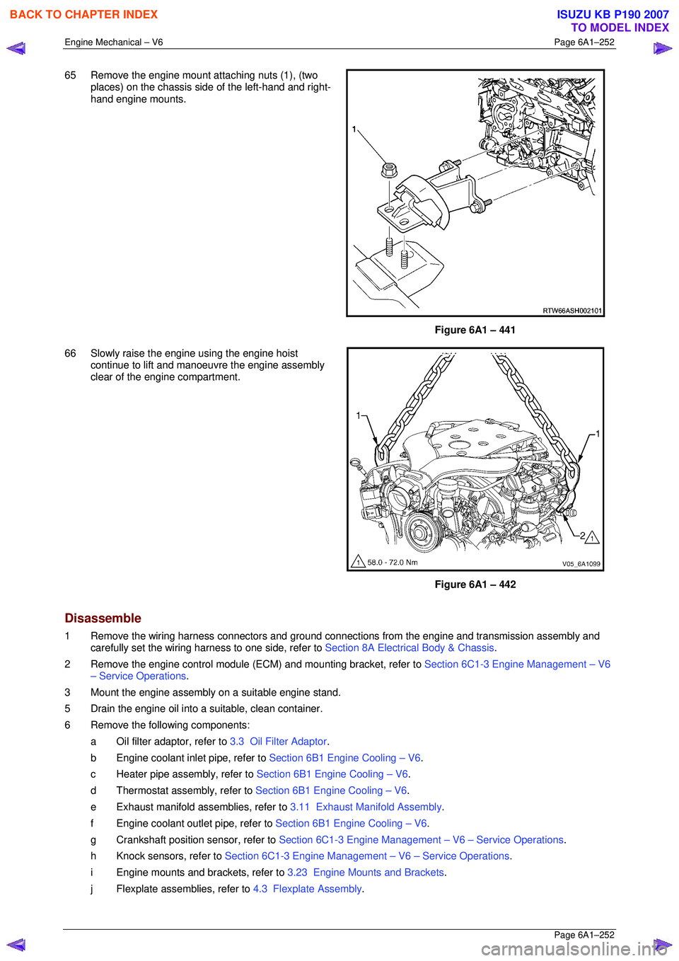
65 Remove the engine mount attaching nuts (1), (two
places) on the chassis si de of the left-hand and right-
hand engine mounts.
Figure 6A1 – 441
66 Slowly raise the engine using the engine hoist continue to lift and manoeuvre the engine assembly
clear of the engine compartment.
Figure 6A1 – 442
Disassemble
1 Remove the wiring harness connectors and ground connec tions from the engine and transmission assembly and
carefully set the wiring harness to one side, refer to Section 8A Electrical Body & Chassis.
2 Remove the engine control module (ECM) and mounting bracket, refer to Section 6C1-3 Engine Management – V6
– Service Operations .
3 Mount the engine assembly on a suitable engine stand.
5 Drain the engine oil into a suitable, clean container.
6 Remove the following components: a Oil filter adaptor, refer to 3.3 Oil Filter Adaptor.
b Engine coolant inlet pipe, refer to Section 6B1 Engine Cooling – V6.
c Heater pipe assembly, refer to Section 6B1 Engine Cooling – V6.
d Thermostat assembly, refer to Section 6B1 Engine Cooling – V6.
e Exhaust manifold a ssemblies, refer to 3.11 Exhaust Manifold Assembly .
f Engine coolant outlet pipe, refer to Section 6B1 Engine Cooling – V6.
g Crankshaft position sensor, refer to Section 6C1-3 Engine Management – V6 – Service Operations.
h Knock sensors, refer to Section 6C1-3 Engine Management – V6 – Service Operations.
i Engine mounts and brackets, refer to 3.23 Engine Mounts and Brackets.
j Flexplate assemblies, refer to 4.3 Flexplate Assembly.
BACK TO CHAPTER INDEX
TO MODEL INDEX
ISUZU KB P190 2007