2007 ISUZU KB P190 Harness
[x] Cancel search: HarnessPage 1206 of 6020
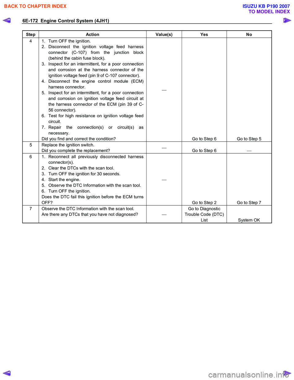
6E-172 Engine Control System (4JH1)
Step Action Value(s) Yes No
4 1. Turn OFF the ignition.
2. Disconnect the ignition voltage feed harness connector (C-107) from the junction block
(behind the cabin fuse block).
3. Inspect for an intermittent, for a poor connection and corrosion at the harness connector of the
ignition voltage feed (pin 9 of C-107 connector).
4. Disconnect the engine control module (ECM) harness connector.
5. Inspect for an intermittent, for a poor connection and corrosion on ignition voltage feed circuit at
the harness connector of the ECM (pin 39 of C-
56 connector).
6. Test for high resistance on ignition voltage feed circuit.
7. Repair the connection(s) or circuit(s) as necessary.
Did you find and correct the condition?
Go to Step 6 Go to Step 5
5 Replace the ignition switch. Did you complete the replacement?
Go to Step 6
6 1. Reconnect all previously disconnected harness
connector(s).
2. Clear the DTCs with the scan tool.
3. Turn OFF the ignition for 30 seconds.
4. Start the engine.
5. Observe the DTC Information with the scan tool.
6. Turn OFF the ignition.
Does the DTC fail this ignition before the ECM turns
OFF?
Go to Step 2 Go to Step 7
7 Observe the DTC Information with the scan tool. Are there any DTCs that you have not diagnosed? Go to Diagnostic
Trouble Code (DTC) List System OK
BACK TO CHAPTER INDEX
TO MODEL INDEX
ISUZU KB P190 2007
Page 1211 of 6020
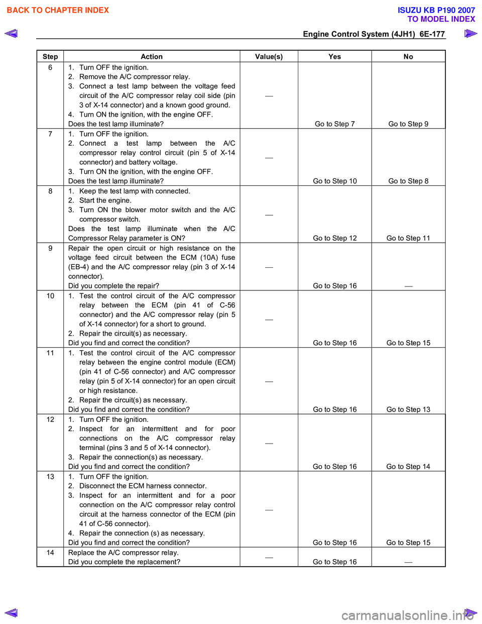
Engine Control System (4JH1) 6E-177
Step Action Value(s) Yes No
6 1. Turn OFF the ignition.
2. Remove the A/C compressor relay.
3. Connect a test lamp between the voltage feed circuit of the A/C compressor relay coil side (pin
3 of X-14 connector) and a known good ground.
4. Turn ON the ignition, with the engine OFF.
Does the test lamp illuminate?
Go to Step 7 Go to Step 9
7 1. Turn OFF the ignition. 2. Connect a test lamp between the A/C compressor relay control circuit (pin 5 of X-14
connector) and battery voltage.
3. Turn ON the ignition, with the engine OFF.
Does the test lamp illuminate?
Go to Step 10 Go to Step 8
8 1. Keep the test lamp with connected. 2. Start the engine.
3. Turn ON the blower motor switch and the A/C compressor switch.
Does the test lamp illuminate when the A/C
Compressor Relay parameter is ON?
Go to Step 12 Go to Step 11
9 Repair the open circuit or high resistance on the voltage feed circuit between the ECM (10A) fuse
(EB-4) and the A/C compressor relay (pin 3 of X-14
connector).
Did you complete the repair?
Go to Step 16
10 1. Test the control circuit of the A/C compressor
relay between the ECM (pin 41 of C-56
connector) and the A/C compressor relay (pin 5
of X-14 connector) for a short to ground.
2. Repair the circuit(s) as necessary.
Did you find and correct the condition?
Go to Step 16 Go to Step 15
11 1. Test the control circuit of the A/C compressor relay between the engine control module (ECM)
(pin 41 of C-56 connector) and A/C compressor
relay (pin 5 of X-14 connector) for an open circuit
or high resistance.
2. Repair the circuit(s) as necessary.
Did you find and correct the condition?
Go to Step 16 Go to Step 13
12 1. Turn OFF the ignition. 2. Inspect for an intermittent and for poor connections on the A/C compressor relay
terminal (pins 3 and 5 of X-14 connector).
3. Repair the connection(s) as necessary.
Did you find and correct the condition?
Go to Step 16 Go to Step 14
13 1. Turn OFF the ignition. 2. Disconnect the ECM harness connector.
3. Inspect for an intermittent and for a poor connection on the A/C compressor relay control
circuit at the harness connector of the ECM (pin
41 of C-56 connector).
4. Repair the connection (s) as necessary.
Did you find and correct the condition?
Go to Step 16 Go to Step 15
14 Replace the A/C compressor relay. Did you complete the replacement?
Go to Step 16
BACK TO CHAPTER INDEX
TO MODEL INDEX
ISUZU KB P190 2007
Page 1212 of 6020

6E-178 Engine Control System (4JH1)
Step Action Value(s) Yes No
15 Important: Replacement ECM must be
programmed.
Replace the ECM. Refer to Engine Control Module
(ECM) Replacement in this section.
Did you complete the replacement?
Go to Step 16
16 1. Reconnect all previously disconnected fuse,
relay or harness connector(s).
2. Clear the DTCs with the scan tool.
3. Turn OFF the ignition for 30 seconds.
4. Turn ON the ignition, with the engine OFF.
5. Turn ON the blower motor switch and the A/C compressor switch.
6. Turn OFF the A/C compressor switch.
7. Monitor the DTC Information with the scan tool.
Does the DTC fail this ignition?
Go to Step 3 Go to Step 17
17 Observe the DTC Information with the scan tool. Are there any DTCs that you have not diagnosed? Go to Diagnostic
Trouble Code (DTC) List System OK
BACK TO CHAPTER INDEX
TO MODEL INDEX
ISUZU KB P190 2007
Page 1214 of 6020
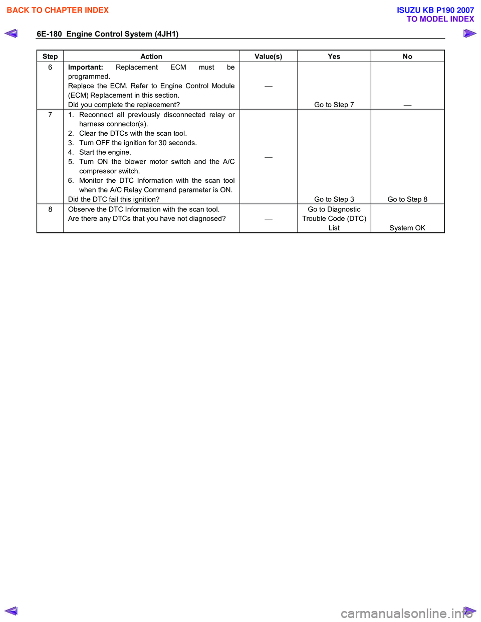
6E-180 Engine Control System (4JH1)
Step Action Value(s) Yes No
6 Important: Replacement ECM must be
programmed.
Replace the ECM. Refer to Engine Control Module
(ECM) Replacement in this section.
Did you complete the replacement?
Go to Step 7
7 1. Reconnect all previously disconnected relay or
harness connector(s).
2. Clear the DTCs with the scan tool.
3. Turn OFF the ignition for 30 seconds.
4. Start the engine.
5. Turn ON the blower motor switch and the A/C compressor switch.
6. Monitor the DTC Information with the scan tool when the A/C Relay Command parameter is ON.
Did the DTC fail this ignition?
Go to Step 3 Go to Step 8
8 Observe the DTC Information with the scan tool. Are there any DTCs that you have not diagnosed? Go to Diagnostic
Trouble Code (DTC) List System OK
BACK TO CHAPTER INDEX
TO MODEL INDEX
ISUZU KB P190 2007
Page 1216 of 6020
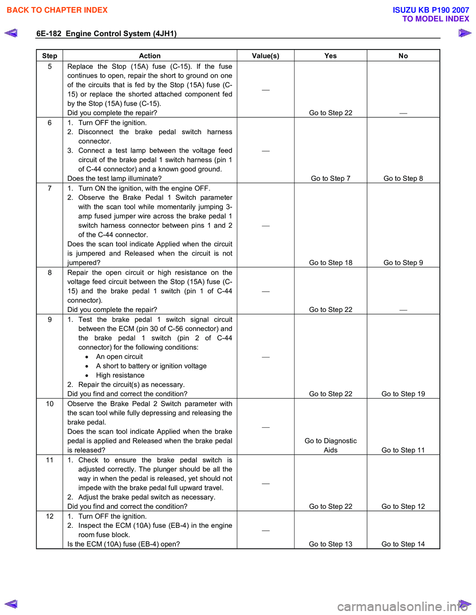
6E-182 Engine Control System (4JH1)
Step Action Value(s) Yes No
5 Replace the Stop (15A) fuse (C-15). If the fuse
continues to open, repair the short to ground on one
of the circuits that is fed by the Stop (15A) fuse (C-
15) or replace the shorted attached component fed
by the Stop (15A) fuse (C-15).
Did you complete the repair?
Go to Step 22
6 1. Turn OFF the ignition.
2. Disconnect the brake pedal switch harness connector.
3. Connect a test lamp between the voltage feed circuit of the brake pedal 1 switch harness (pin 1
of C-44 connector) and a known good ground.
Does the test lamp illuminate?
Go to Step 7 Go to Step 8
7 1. Turn ON the ignition, with the engine OFF. 2. Observe the Brake Pedal 1 Switch parameter with the scan tool while momentarily jumping 3-
amp fused jumper wire across the brake pedal 1
switch harness connector between pins 1 and 2
of the C-44 connector.
Does the scan tool indicate Applied when the circuit
is jumpered and Released when the circuit is not
jumpered?
Go to Step 18 Go to Step 9
8 Repair the open circuit or high resistance on the voltage feed circuit between the Stop (15A) fuse (C-
15) and the brake pedal 1 switch (pin 1 of C-44
connector).
Did you complete the repair?
Go to Step 22
9 1. Test the brake pedal 1 switch signal circuit
between the ECM (pin 30 of C-56 connector) and
the brake pedal 1 switch (pin 2 of C-44
connector) for the following conditions: • An open circuit
• A short to battery or ignition voltage
• High resistance
2. Repair the circuit(s) as necessary.
Did you find and correct the condition?
Go to Step 22 Go to Step 19
10 Observe the Brake Pedal 2 Switch parameter with the scan tool while fully depressing and releasing the
brake pedal.
Does the scan tool indicate Applied when the brake
pedal is applied and Released when the brake pedal
is released?
Go to Diagnostic Aids Go to Step 11
11 1. Check to ensure the brake pedal switch is
adjusted correctly. The plunger should be all the
way in when the pedal is released, yet should not
impede with the brake pedal full upward travel.
2. Adjust the brake pedal switch as necessary.
Did you find and correct the condition?
Go to Step 22 Go to Step 12
12 1. Turn OFF the ignition. 2. Inspect the ECM (10A) fuse (EB-4) in the engine room fuse block.
Is the ECM (10A) fuse (EB-4) open?
Go to Step 13 Go to Step 14
BACK TO CHAPTER INDEX
TO MODEL INDEX
ISUZU KB P190 2007
Page 1217 of 6020
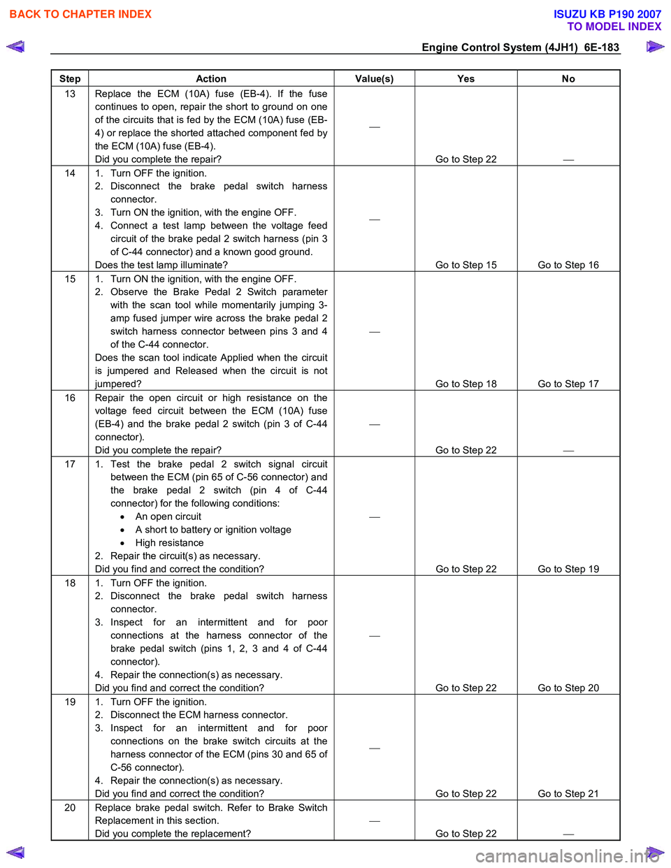
Engine Control System (4JH1) 6E-183
Step Action Value(s) Yes No
13 Replace the ECM (10A) fuse (EB-4). If the fuse
continues to open, repair the short to ground on one
of the circuits that is fed by the ECM (10A) fuse (EB-
4) or replace the shorted attached component fed by
the ECM (10A) fuse (EB-4).
Did you complete the repair?
Go to Step 22
14 1. Turn OFF the ignition.
2. Disconnect the brake pedal switch harness connector.
3. Turn ON the ignition, with the engine OFF.
4. Connect a test lamp between the voltage feed circuit of the brake pedal 2 switch harness (pin 3
of C-44 connector) and a known good ground.
Does the test lamp illuminate?
Go to Step 15 Go to Step 16
15 1. Turn ON the ignition, with the engine OFF. 2. Observe the Brake Pedal 2 Switch parameter with the scan tool while momentarily jumping 3-
amp fused jumper wire across the brake pedal 2
switch harness connector between pins 3 and 4
of the C-44 connector.
Does the scan tool indicate Applied when the circuit
is jumpered and Released when the circuit is not
jumpered?
Go to Step 18 Go to Step 17
16 Repair the open circuit or high resistance on the voltage feed circuit between the ECM (10A) fuse
(EB-4) and the brake pedal 2 switch (pin 3 of C-44
connector).
Did you complete the repair?
Go to Step 22
17 1. Test the brake pedal 2 switch signal circuit
between the ECM (pin 65 of C-56 connector) and
the brake pedal 2 switch (pin 4 of C-44
connector) for the following conditions: • An open circuit
• A short to battery or ignition voltage
• High resistance
2. Repair the circuit(s) as necessary.
Did you find and correct the condition?
Go to Step 22 Go to Step 19
18 1. Turn OFF the ignition. 2. Disconnect the brake pedal switch harness connector.
3. Inspect for an intermittent and for poor connections at the harness connector of the
brake pedal switch (pins 1, 2, 3 and 4 of C-44
connector).
4. Repair the connection(s) as necessary.
Did you find and correct the condition?
Go to Step 22 Go to Step 20
19 1. Turn OFF the ignition. 2. Disconnect the ECM harness connector.
3. Inspect for an intermittent and for poor connections on the brake switch circuits at the
harness connector of the ECM (pins 30 and 65 of
C-56 connector).
4. Repair the connection(s) as necessary.
Did you find and correct the condition?
Go to Step 22 Go to Step 21
20 Replace brake pedal switch. Refer to Brake Switch Replacement in this section.
Did you complete the replacement?
Go to Step 22
BACK TO CHAPTER INDEX
TO MODEL INDEX
ISUZU KB P190 2007
Page 1218 of 6020
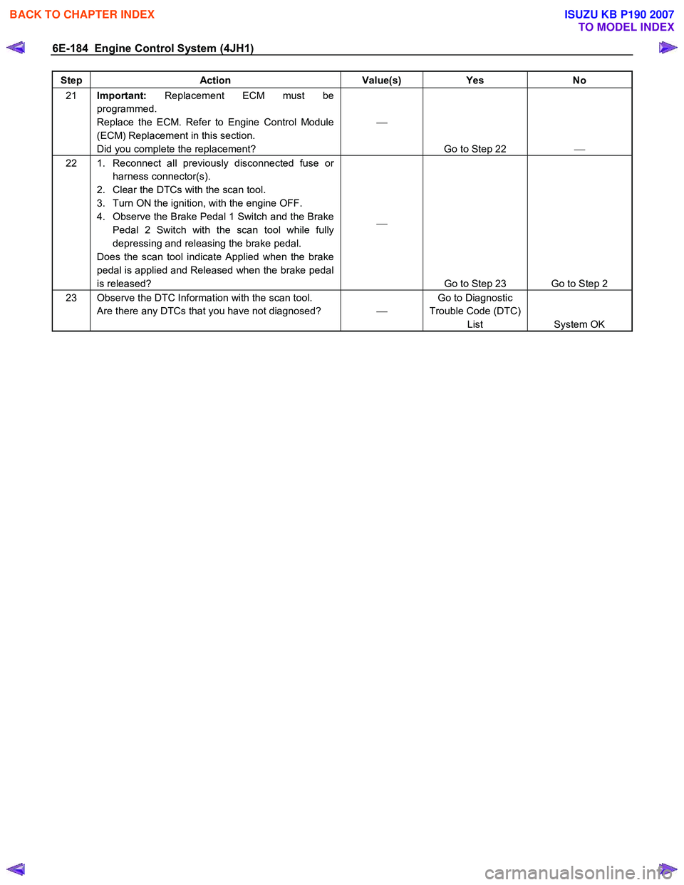
6E-184 Engine Control System (4JH1)
Step Action Value(s) Yes No
21 Important: Replacement ECM must be
programmed.
Replace the ECM. Refer to Engine Control Module
(ECM) Replacement in this section.
Did you complete the replacement?
Go to Step 22
22 1. Reconnect all previously disconnected fuse or
harness connector(s).
2. Clear the DTCs with the scan tool.
3. Turn ON the ignition, with the engine OFF.
4. Observe the Brake Pedal 1 Switch and the Brake Pedal 2 Switch with the scan tool while fully
depressing and releasing the brake pedal.
Does the scan tool indicate Applied when the brake
pedal is applied and Released when the brake pedal
is released?
Go to Step 23 Go to Step 2
23 Observe the DTC Information with the scan tool. Are there any DTCs that you have not diagnosed? Go to Diagnostic
Trouble Code (DTC) List System OK
BACK TO CHAPTER INDEX
TO MODEL INDEX
ISUZU KB P190 2007
Page 1220 of 6020
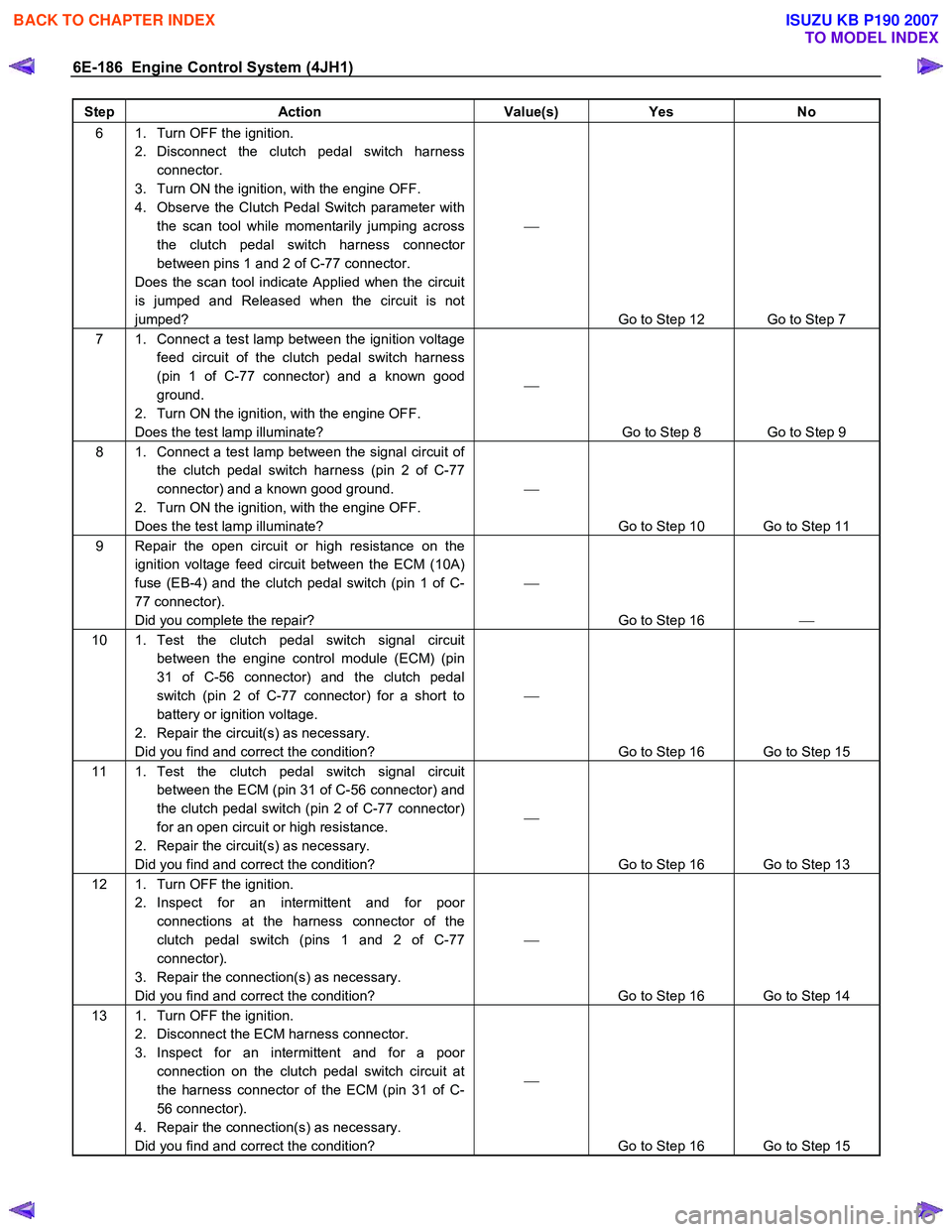
6E-186 Engine Control System (4JH1)
Step Action Value(s) Yes No
6 1. Turn OFF the ignition.
2. Disconnect the clutch pedal switch harness connector.
3. Turn ON the ignition, with the engine OFF.
4. Observe the Clutch Pedal Switch parameter with the scan tool while momentarily jumping across
the clutch pedal switch harness connector
between pins 1 and 2 of C-77 connector.
Does the scan tool indicate Applied when the circuit
is jumped and Released when the circuit is not
jumped?
Go to Step 12 Go to Step 7
7 1. Connect a test lamp between the ignition voltage feed circuit of the clutch pedal switch harness
(pin 1 of C-77 connector) and a known good
ground.
2. Turn ON the ignition, with the engine OFF.
Does the test lamp illuminate?
Go to Step 8 Go to Step 9
8 1. Connect a test lamp between the signal circuit of the clutch pedal switch harness (pin 2 of C-77
connector) and a known good ground.
2. Turn ON the ignition, with the engine OFF.
Does the test lamp illuminate?
Go to Step 10 Go to Step 11
9 Repair the open circuit or high resistance on the ignition voltage feed circuit between the ECM (10A)
fuse (EB-4) and the clutch pedal switch (pin 1 of C-
77 connector).
Did you complete the repair?
Go to Step 16
10 1. Test the clutch pedal switch signal circuit
between the engine control module (ECM) (pin
31 of C-56 connector) and the clutch pedal
switch (pin 2 of C-77 connector) for a short to
battery or ignition voltage.
2. Repair the circuit(s) as necessary.
Did you find and correct the condition?
Go to Step 16 Go to Step 15
11 1. Test the clutch pedal switch signal circuit between the ECM (pin 31 of C-56 connector) and
the clutch pedal switch (pin 2 of C-77 connector)
for an open circuit or high resistance.
2. Repair the circuit(s) as necessary.
Did you find and correct the condition?
Go to Step 16 Go to Step 13
12 1. Turn OFF the ignition. 2. Inspect for an intermittent and for poor connections at the harness connector of the
clutch pedal switch (pins 1 and 2 of C-77
connector).
3. Repair the connection(s) as necessary.
Did you find and correct the condition?
Go to Step 16 Go to Step 14
13 1. Turn OFF the ignition. 2. Disconnect the ECM harness connector.
3. Inspect for an intermittent and for a poor connection on the clutch pedal switch circuit at
the harness connector of the ECM (pin 31 of C-
56 connector).
4. Repair the connection(s) as necessary.
Did you find and correct the condition?
Go to Step 16 Go to Step 15
BACK TO CHAPTER INDEX
TO MODEL INDEX
ISUZU KB P190 2007