2007 ISUZU KB P190 DTC CHECK
[x] Cancel search: DTC CHECKPage 1680 of 6020
ENGINE CONTROL SYSTEM (4JK1/4JJ1) 6E-63
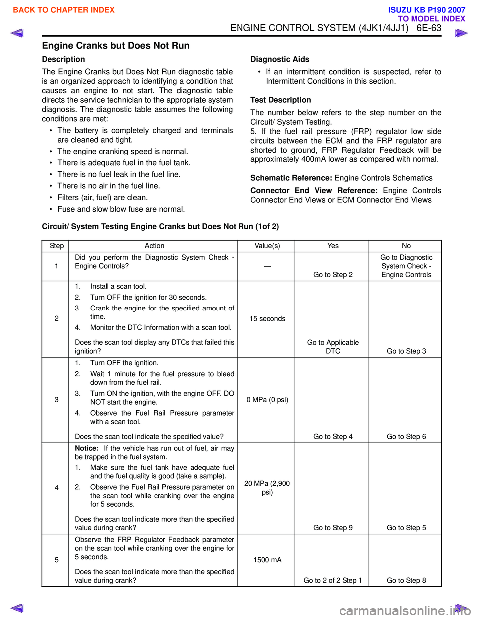
Engine Cranks but Does Not Run
Description
The Engine Cranks but Does Not Run diagnostic table
is an organized approach to identifying a condition that
causes an engine to not start. The diagnostic table
directs the service technician to the appropriate system
diagnosis. The diagnostic table assumes the following
conditions are met:
• The battery is completely charged and terminals are cleaned and tight.
• The engine cranking speed is normal.
• There is adequate fuel in the fuel tank.
• There is no fuel leak in the fuel line.
• There is no air in the fuel line.
• Filters (air, fuel) are clean.
• Fuse and slow blow fuse are normal. Diagnostic Aids
• If an intermittent condition is suspected, refer to Intermittent Conditions in this section.
Test Description
The number below refers to the step number on the
Circuit/ System Testing.
5. If the fuel rail pressure (FRP) regulator low side
circuits between the ECM and the FRP regulator are
shorted to ground, FRP Regulator Feedback will be
approximately 400mA lower as compared with normal.
Schematic Reference: Engine Controls Schematics
Connector End View Reference: Engine Controls
Connector End Views or ECM Connector End Views
Circuit/ System Testing Engine Cranks but Does Not Run (1of 2)
Step Action Value(s)Yes No
1 Did you perform the Diagnostic System Check -
Engine Controls? —
Go to Step 2 Go to Diagnostic
System Check -
Engine Controls
2 1. Install a scan tool.
2. Turn OFF the ignition for 30 seconds.
3. Crank the engine for the specified amount of time.
4. Monitor the DTC Information with a scan tool.
Does the scan tool display any DTCs that failed this
ignition? 15 seconds
Go to Applicable DTC Go to Step 3
3 1. Turn OFF the ignition.
2. Wait 1 minute for the fuel pressure to bleed down from the fuel rail.
3. Turn ON the ignition, with the engine OFF. DO NOT start the engine.
4. Observe the Fuel Rail Pressure parameter with a scan tool.
Does the scan tool indicate the specified value? 0 MPa (0 psi)
Go to Step 4 Go to Step 6
4 Notice:
If the vehicle has run out of fuel, air may
be trapped in the fuel system.
1. Make sure the fuel tank have adequate fuel and the fuel quality is good (take a sample).
2. Observe the Fuel Rail Pressure parameter on the scan tool while cranking over the engine
for 5 seconds.
Does the scan tool indicate more than the specified
value during crank? 20 MPa (2,900
psi)
Go to Step 9 Go to Step 5
5 Observe the FRP Regulator Feedback parameter
on the scan tool while cranking over the engine for
5 seconds.
Does the scan tool indicate more than the specified
value during crank? 1500 mA
Go to 2 of 2 Step 1 Go to Step 8
BACK TO CHAPTER INDEX
TO MODEL INDEX
ISUZU KB P190 2007
Page 1681 of 6020
6E-64 ENGINE CONTROL SYSTEM (4JK1/4JJ1)
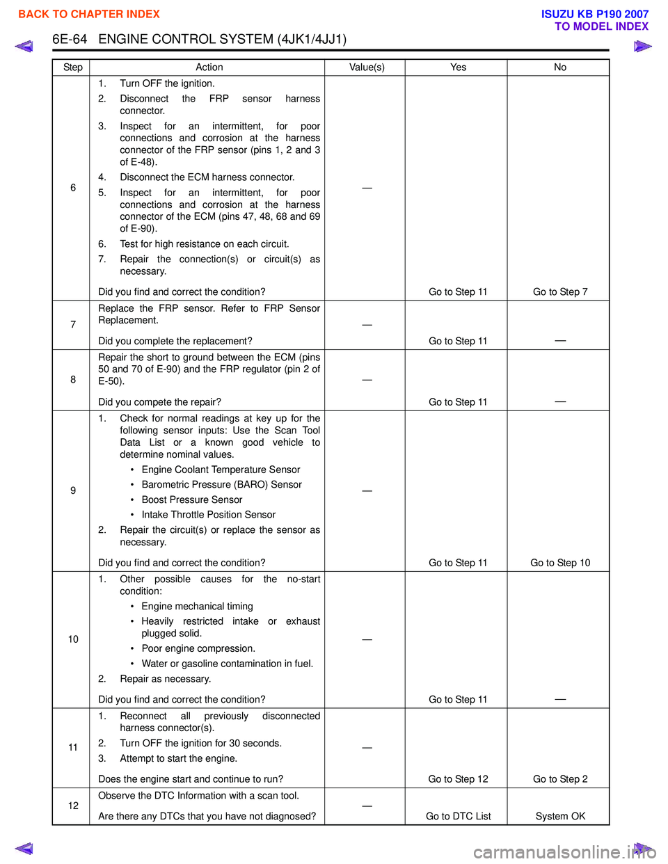
61. Turn OFF the ignition.
2. Disconnect the FRP sensor harness connector.
3. Inspect for an intermittent, for poor connections and corrosion at the harness
connector of the FRP sensor (pins 1, 2 and 3
of E-48).
4. Disconnect the ECM harness connector.
5. Inspect for an intermittent, for poor connections and corrosion at the harness
connector of the ECM (pins 47, 48, 68 and 69
of E-90).
6. Test for high resistance on each circuit.
7. Repair the connection(s) or circuit(s) as necessary.
Did you find and correct the condition? —
Go to Step 11 Go to Step 7
7 Replace the FRP sensor. Refer to FRP Sensor
Replacement.
Did you complete the replacement? —
Go to Step 11
—
8Repair the short to ground between the ECM (pins
50 and 70 of E-90) and the FRP regulator (pin 2 of
E-50).
Did you compete the repair? —
Go to Step 11
—
91. Check for normal readings at key up for the
following sensor inputs: Use the Scan Tool
Data List or a known good vehicle to
determine nominal values.
• Engine Coolant Temperature Sensor
• Barometric Pressure (BARO) Sensor
• Boost Pressure Sensor
• Intake Throttle Position Sensor
2. Repair the circuit(s) or replace the sensor as necessary.
Did you find and correct the condition? —
Go to Step 11 Go to Step 10
10 1. Other possible causes for the no-start
condition:
• Engine mechanical timing
• Heavily restricted intake or exhaust plugged solid.
• Poor engine compression.
• Water or gasoline contamination in fuel.
2. Repair as necessary.
Did you find and correct the condition? —
Go to Step 11
—
111. Reconnect all previously disconnected
harness connector(s).
2. Turn OFF the ignition for 30 seconds.
3. Attempt to start the engine.
Does the engine start and continue to run? —
Go to Step 12 Go to Step 2
12 Observe the DTC Information with a scan tool.
Are there any DTCs that you have not diagnosed? —
Go to DTC List System OK
Step
Action Value(s)Yes No
BACK TO CHAPTER INDEX
TO MODEL INDEX
ISUZU KB P190 2007
Page 1686 of 6020
ENGINE CONTROL SYSTEM (4JK1/4JJ1) 6E-69
DTC P0016 (Flash Code 16)
Circuit Description
The crankshaft position (CKP) sensor is located on the
left-hand of the cylinder block rear and it is behind the
starter motor. The sensor rotor is fixed on the
crankshaft. There are 56 notches spaced 6 ° apart and
a 30 ° section that is open span. This open span portion
allows for the detection of top dead center (TDC).
The camshaft position (CMP) sensor is installed on the
timing chain sprocket cover at the front of the camshaft
idle gear. The CMP sensor detects total of five
projections per one engine cycle (four projections
arranged equally every 90 ° and one reference
projection on the timing chain sprocket surface).
Detecting the open span portion from the CKP sensor
and one reference projection from the CMP sensor, the
ECM determines cylinder #1 compression TDC to
ensure they correlate with each other. If the ECM
detects both signals are out of synchronization, this
DTC will set.
Condition for Running the DTC • DTCs P0335, P0336, P0340 and P0341 are not set.
• The battery voltage is more than 9 volts.
• The ignition switch is ON.
• The CKP sensor signal pulse is detected.
• The CMP sensor signal pulse is detected. Condition for Setting the DTC
• The ECM detects that the CKP sensor signals and CMP sensor signals are out of synchronization
during engine rotations.
Action Taken When the DTC Sets • The ECM illuminates the SVS lamp when the diagnostic runs and fails. Refer to DTC Type
Definitions for Action Taken When the DTC Sets -
Type C. (Euro 4 Specification)
• The ECM illuminates the MIL when the diagnostic runs and fails. Refer to DTC Type Definitions for
Action Taken When the DTC Sets - Type A.
(Except Euro 4 Specification)
Condition for Clearing the DTC • Refer to DTC Type Definitions for Condition for Clearing the SVS Lamp/ DTC - Type C. (Euro 4
Specification)
• Refer to DTC Type Definitions for Condition for Clearing the MIL/ DTC - Type A. (Except Euro 4
Specification)
Diagnostic Aids • This DTC is caused by an incorrect mechanical timing condition, which is most likely caused by
wrong installation of timing gear or chain.
• The engine reverse rotation may set this DTC.
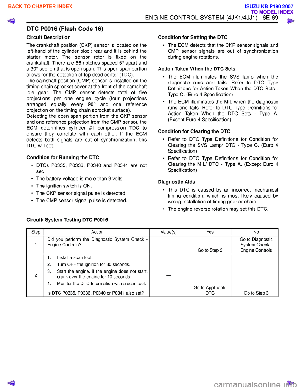
Circuit/ System Testing DTC P0016
Step Action Value(s)Yes No
1 Did you perform the Diagnostic System Check -
Engine Controls? —
Go to Step 2 Go to Diagnostic
System Check -
Engine Controls
2 1. Install a scan tool.
2. Turn OFF the ignition for 30 seconds.
3. Start the engine. If the engine does not start, crank over the engine for 10 seconds.
4. Monitor the DTC Information with a scan tool.
Is DTC P0335, P0336, P0340 or P0341 also set? —
Go to Applicable DTC Go to Step 3
BACK TO CHAPTER INDEX
TO MODEL INDEX
ISUZU KB P190 2007
Page 1688 of 6020
ENGINE CONTROL SYSTEM (4JK1/4JJ1) 6E-71
DTC P0045 (Flash Code 33)
Circuit Description
The position of the turbocharger nozzle is controlled by
the ECM. The ECM utilizes a turbocharger nozzle
control solenoid valve and a boost pressure sensor to
control the turbocharger nozzles. When the engine is
not under load, the turbocharger nozzles are in an open
position, or no boost condition. When the engine is
under load, the ECM commands the control solenoid
valve to close the turbocharger nozzles, thus
increasing the boost. The ECM will vary the boost
dependant upon the load requirements of the engine.
The ECM uses a pulse width modulation (PWM) on the
control circuit to open and control the solenoid valve. If
the ECM detects an open circuit or short circuit on the
solenoid valve circuit, this DTC will set.
Condition for Running the DTC • The ignition switch is ON.
Condition for Setting the DTC
Either of following condition is met: • The ECM detects a low voltage condition on the turbocharger nozzle control solenoid circuit when
the solenoid is commanded OFF.
• The ECM detects a high voltage condition on the turbocharger nozzle control solenoid circuit when
the solenoid is commanded ON. Action Taken When the DTC Sets
• The ECM illuminates the MIL when the diagnostic runs and fails. Refer to DTC Type Definitions for
Action Taken When the DTC Sets - Type A.
• The ECM limits fuel injection quantity.
• The ECM inhibits pilot injection.
• The ECM inhibits cruise control.
Condition for Clearing the DTC • Refer to DTC Type Definitions for Condition for Clearing the MIL/ DTC - Type A.
Diagnostic Aids • If an intermittent condition is suspected, refer to Intermittent Conditions in this section.
Test description
The number below refers to the step number on the
Circuit/ System Testing.
4. If the solenoid control circuit between the ECM and
the solenoid is normal, the test lamp changes from
Bright to Dim when commanded from Increase to
Decrease.
Schematic Reference: Vacuum Hose Routing
Diagram and Engine Controls Schematics
Connector End View Reference: Engine Controls
Connector End Views or ECM Connector End Views
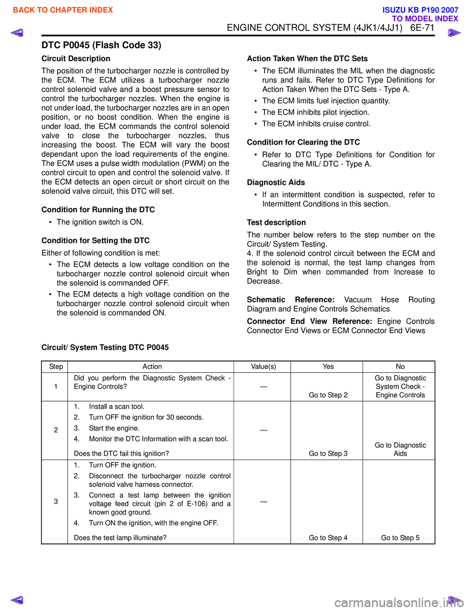
Circuit/ System Testing DTC P0045
Step Action Value(s)Yes No
1 Did you perform the Diagnostic System Check -
Engine Controls? —
Go to Step 2 Go to Diagnostic
System Check -
Engine Controls
2 1. Install a scan tool.
2. Turn OFF the ignition for 30 seconds.
3. Start the engine.
4. Monitor the DTC Information with a scan tool.
Does the DTC fail this ignition? —
Go to Step 3 Go to Diagnostic
Aids
3 1. Turn OFF the ignition.
2. Disconnect the turbocharger nozzle control solenoid valve harness connector.
3. Connect a test lamp between the ignition voltage feed circuit (pin 2 of E-106) and a
known good ground.
4. Turn ON the ignition, with the engine OFF.
Does the test lamp illuminate? —
Go to Step 4 Go to Step 5
BACK TO CHAPTER INDEX
TO MODEL INDEX
ISUZU KB P190 2007
Page 1689 of 6020
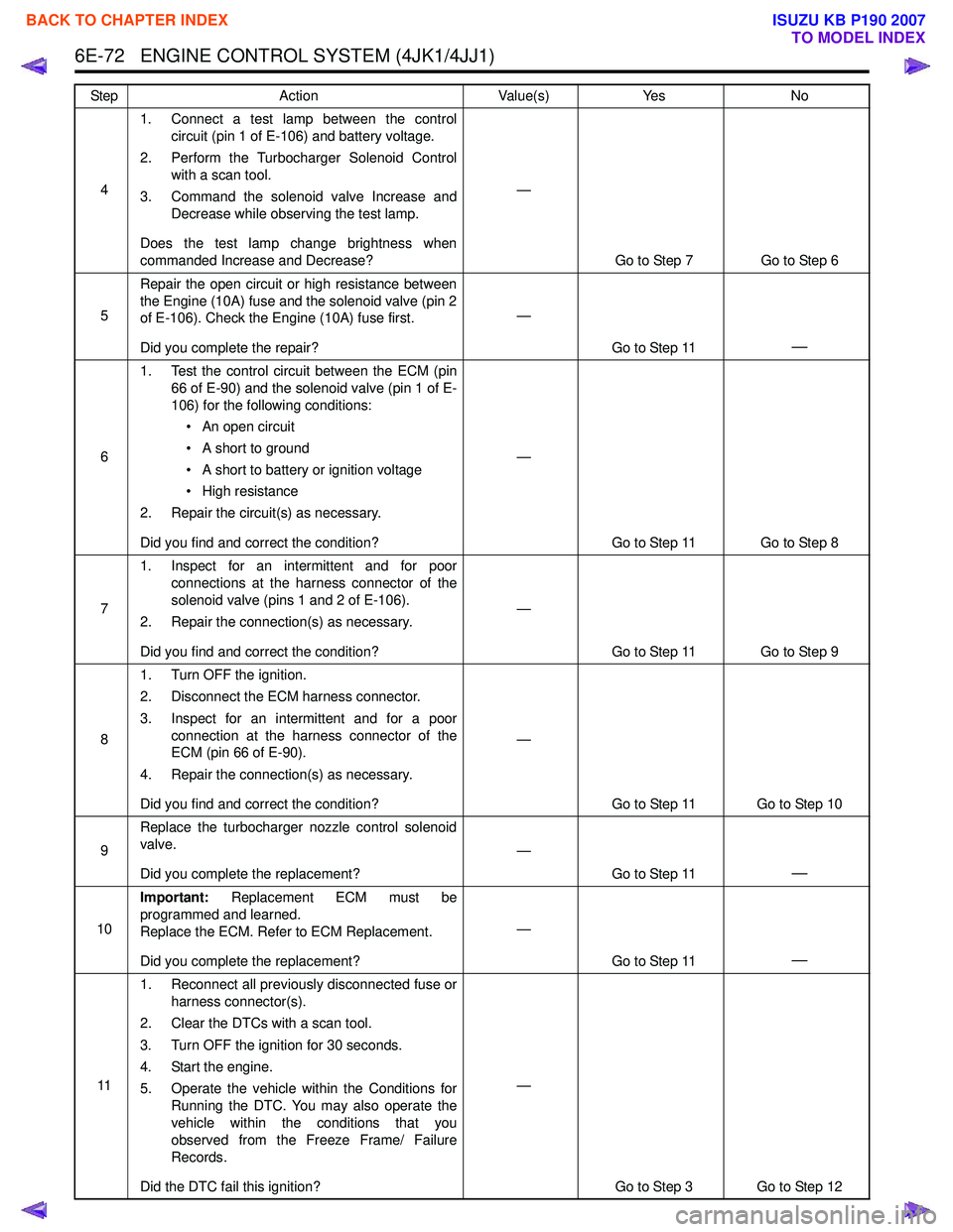
6E-72 ENGINE CONTROL SYSTEM (4JK1/4JJ1)
41. Connect a test lamp between the control
circuit (pin 1 of E-106) and battery voltage.
2. Perform the Turbocharger Solenoid Control with a scan tool.
3. Command the solenoid valve Increase and Decrease while observing the test lamp.
Does the test lamp change brightness when
commanded Increase and Decrease? —
Go to Step 7 Go to Step 6
5 Repair the open circuit or high resistance between
the Engine (10A) fuse and the solenoid valve (pin 2
of E-106). Check the Engine (10A) fuse first.
Did you complete the repair? —
Go to Step 11
—
61. Test the control circuit between the ECM (pin
66 of E-90) and the solenoid valve (pin 1 of E-
106) for the following conditions:
• An open circuit
• A short to ground
• A short to battery or ignition voltage
• High resistance
2. Repair the circuit(s) as necessary.
Did you find and correct the condition? —
Go to Step 11 Go to Step 8
7 1. Inspect for an intermittent and for poor
connections at the harness connector of the
solenoid valve (pins 1 and 2 of E-106).
2. Repair the connection(s) as necessary.
Did you find and correct the condition? —
Go to Step 11 Go to Step 9
8 1. Turn OFF the ignition.
2. Disconnect the ECM harness connector.
3. Inspect for an intermittent and for a poor connection at the harness connector of the
ECM (pin 66 of E-90).
4. Repair the connection(s) as necessary.
Did you find and correct the condition? —
Go to Step 11 Go to Step 10
9 Replace the turbocharger nozzle control solenoid
valve.
Did you complete the replacement? —
Go to Step 11
—
10Important:
Replacement ECM must be
programmed and learned.
Replace the ECM. Refer to ECM Replacement.
Did you complete the replacement? —
Go to Step 11
—
111. Reconnect all previously disconnected fuse or
harness connector(s).
2. Clear the DTCs with a scan tool.
3. Turn OFF the ignition for 30 seconds.
4. Start the engine.
5. Operate the vehicle within the Conditions for Running the DTC. You may also operate the
vehicle within the conditions that you
observed from the Freeze Frame/ Failure
Records.
Did the DTC fail this ignition? —
Go to Step 3 Go to Step 12
Step Action Value(s) Yes No
BACK TO CHAPTER INDEX
TO MODEL INDEX
ISUZU KB P190 2007
Page 1691 of 6020

6E-74 ENGINE CONTROL SYSTEM (4JK1/4JJ1)
DTC P0087 (Flash Code 225)
Description
The common rail fuel system is comprised of two fuel
pressure sections: a suction side between the fuel tank
and the fuel supply pump and a high-pressure side
between the fuel supply pump and the fuel injectors.
Fuel is drawn from the fuel tank via a feed pump and
then pumped into the fuel rail by two plungers, all of
which are internal to the fuel supply pump. This high
pressure is regulated by the ECM using the fuel rail
pressure (FRP) regulator dependant upon values from
the FRP sensor attached to the fuel rail. In case of fuel
rail overpressure, a pressure limiter valve threaded into
the fuel rail will open to release overpressure and
return fuel back to the fuel tank. If the ECM detects that
the fuel rail pressure went excessively high, then
sharply decreased, this DTC will set indicating high fuel
pressure, which activated the pressure limiter valve.
Condition for Running the DTC • DTCs P0192 and P0193 are not set.
• The battery voltage is more than 9 volts.
• The ignition switch is ON.
• The engine is running.
Condition for Setting the DTC • The ECM detects that the pressure limiter valve is activated with overpressure (more than 190 MPa
[27,600 psi]) in the fuel rail.
Action Taken When the DTC Sets • The ECM illuminates the MIL when the diagnostic runs and fails. Refer to DTC Type Definitions for
Action Taken When the DTC Sets - Type A. • The ECM limits fuel injection quantity.
• The ECM inhibits pilot injection.
• The ECM inhibits cruise control.
Condition for Clearing the DTC • Refer to DTC Type Definitions for Condition for Clearing the MIL/ DTC - Type A.
Diagnostic Aids • An intermittently sticking FRP regulator may have allowed the fuel pressure to become high enough
to open the pressure limiter valve.
• A skewed FRP sensor value can set this DTC. The FRP Sensor on the scan tool should read 0.9 to
1.0 volt with the key ON and engine OFF after the
engine has stopped running for a minimum of 1
minute.
Notice: • If the fuel tank is empty or near empty, air might be allowed to go into the fuel system. With air in the
fuel system, smooth flow of fuel into the supply
pump is interrupted and this DTC may set. Perform
bleeding of fuel system after refilling.
Schematic Reference: Fuel System Routing Diagram
and Engine Controls Schematics
Connector End View Reference: Engine Controls
Connector End Views or ECM Connector End Views
Circuit/ System Testing DTC P0087
Step Action Value(s)Yes No
1 Did you perform the Diagnostic System Check -
Engine Controls? —
Go to Step 2 Go to Diagnostic
System Check -
Engine Controls
2 1. Install a scan tool.
2. Turn OFF the ignition for 30 seconds.
3. Start the engine.
4. Monitor the DTC Information with a scan tool.
Is DTC P0088, P0089, P0091, P0092, P0192,
P0193, P0201 - P0204, P1064, P1065, P124B or
P2146 - P2151 set? —
Go to Applicable DTC Go to Step 3
BACK TO CHAPTER INDEX
TO MODEL INDEX
ISUZU KB P190 2007
Page 1692 of 6020
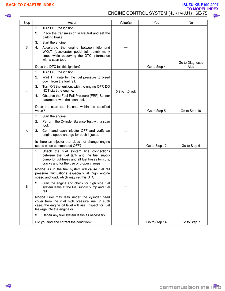
ENGINE CONTROL SYSTEM (4JK1/4JJ1) 6E-75
31. Turn OFF the ignition.
2. Place the transmission in Neutral and set the parking brake.
3. Start the engine.
4. Accelerate the engine between idle and W.O.T. (accelerator pedal full travel) many
times while observing the DTC Information
with a scan tool.
Does the DTC fail this ignition? —
Go to Step 4 Go to Diagnostic
Aids
4 1. Turn OFF the ignition.
2. Wait 1 minute for the fuel pressure to bleed down from the fuel rail.
3. Turn ON the ignition, with the engine OFF. DO NOT start the engine.
4. Observe the Fuel Rail Pressure (FRP) Sensor parameter with the scan tool.
Does the scan tool indicate within the specified
value? 0.9 to 1.0 volt
Go to Step 5 Go to Step 10
5 1. Start the engine.
2. Perform the Cylinder Balance Test with a scan tool.
3. Command each injector OFF and verify an engine speed change for each injector.
Is there an injector that does not change engine
speed when commanded OFF? —
Go to Step 12 Go to Step 6
6 1. Check the fuel system line connections
between the fuel tank and the fuel supply
pump for tightness and all fuel hoses for cuts,
cracks and for the use of proper clamps.
Notice: Air in the fuel system will cause fuel rail
pressure fluctuations especially at high engine
speed and load, which may set this DTC.
2. Start the engine and check for high side fuel system leaks at the fuel supply pump and fuel
rail.
Notice: Fuel may leak under the cylinder head
cover from the inlet high pressure line. In such
case, the engine oil level will rise. Inspect for fuel
leakage into the engine oil.
3. Repair any fuel system leaks as necessary.
Did you find and correct the condition? —
Go to Step 14 Go to Step 7
Step
Action Value(s)Yes No
BACK TO CHAPTER INDEX
TO MODEL INDEX
ISUZU KB P190 2007
Page 1696 of 6020
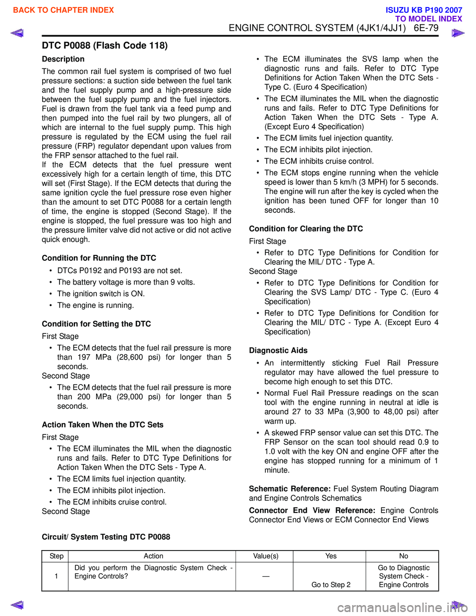
ENGINE CONTROL SYSTEM (4JK1/4JJ1) 6E-79
DTC P0088 (Flash Code 118)
Description
The common rail fuel system is comprised of two fuel
pressure sections: a suction side between the fuel tank
and the fuel supply pump and a high-pressure side
between the fuel supply pump and the fuel injectors.
Fuel is drawn from the fuel tank via a feed pump and
then pumped into the fuel rail by two plungers, all of
which are internal to the fuel supply pump. This high
pressure is regulated by the ECM using the fuel rail
pressure (FRP) regulator dependant upon values from
the FRP sensor attached to the fuel rail.
If the ECM detects that the fuel pressure went
excessively high for a certain length of time, this DTC
will set (First Stage). If the ECM detects that during the
same ignition cycle the fuel pressure rose even higher
than the amount to set DTC P0088 for a certain length
of time, the engine is stopped (Second Stage). If the
engine is stopped, the fuel pressure was too high and
the pressure limiter valve did not active or did not active
quick enough.
Condition for Running the DTC • DTCs P0192 and P0193 are not set.
• The battery voltage is more than 9 volts.
• The ignition switch is ON.
• The engine is running.
Condition for Setting the DTC
First Stage • The ECM detects that the fuel rail pressure is more than 197 MPa (28,600 psi) for longer than 5
seconds.
Second Stage
• The ECM detects that the fuel rail pressure is more than 200 MPa (29,000 psi) for longer than 5
seconds.
Action Taken When the DTC Sets
First Stage • The ECM illuminates the MIL when the diagnostic runs and fails. Refer to DTC Type Definitions for
Action Taken When the DTC Sets - Type A.
• The ECM limits fuel injection quantity.
• The ECM inhibits pilot injection.
• The ECM inhibits cruise control.
Second Stage • The ECM illuminates the SVS lamp when the
diagnostic runs and fails. Refer to DTC Type
Definitions for Action Taken When the DTC Sets -
Type C. (Euro 4 Specification)
• The ECM illuminates the MIL when the diagnostic runs and fails. Refer to DTC Type Definitions for
Action Taken When the DTC Sets - Type A.
(Except Euro 4 Specification)
• The ECM limits fuel injection quantity.
• The ECM inhibits pilot injection.
• The ECM inhibits cruise control.
• The ECM stops engine running when the vehicle speed is lower than 5 km/h (3 MPH) for 5 seconds.
The engine will run after the key is cycled when the
ignition has been tuned OFF for longer than 10
seconds.
Condition for Clearing the DTC
First Stage • Refer to DTC Type Definitions for Condition for Clearing the MIL/ DTC - Type A.
Second Stage
• Refer to DTC Type Definitions for Condition for Clearing the SVS Lamp/ DTC - Type C. (Euro 4
Specification)
• Refer to DTC Type Definitions for Condition for Clearing the MIL/ DTC - Type A. (Except Euro 4
Specification)
Diagnostic Aids • An intermittently sticking Fuel Rail Pressure regulator may have allowed the fuel pressure to
become high enough to set this DTC.
• Normal Fuel Rail Pressure readings on the scan tool with the engine running in neutral at idle is
around 27 to 33 MPa (3,900 to 48,00 psi) after
warm up.
• A skewed FRP sensor value can set this DTC. The FRP Sensor on the scan tool should read 0.9 to
1.0 volt with the key ON and engine OFF after the
engine has stopped running for a minimum of 1
minute.
Schematic Reference: Fuel System Routing Diagram
and Engine Controls Schematics
Connector End View Reference: Engine Controls
Connector End Views or ECM Connector End Views
Circuit/ System Testing DTC P0088
Step Action Value(s)Yes No
1 Did you perform the Diagnostic System Check -
Engine Controls? —
Go to Step 2 Go to Diagnostic
System Check -
Engine Controls
BACK TO CHAPTER INDEX
TO MODEL INDEX
ISUZU KB P190 2007