2007 ISUZU KB P190 DTC CHECK
[x] Cancel search: DTC CHECKPage 1271 of 6020
Engine Control System (4JH1) 6E-237
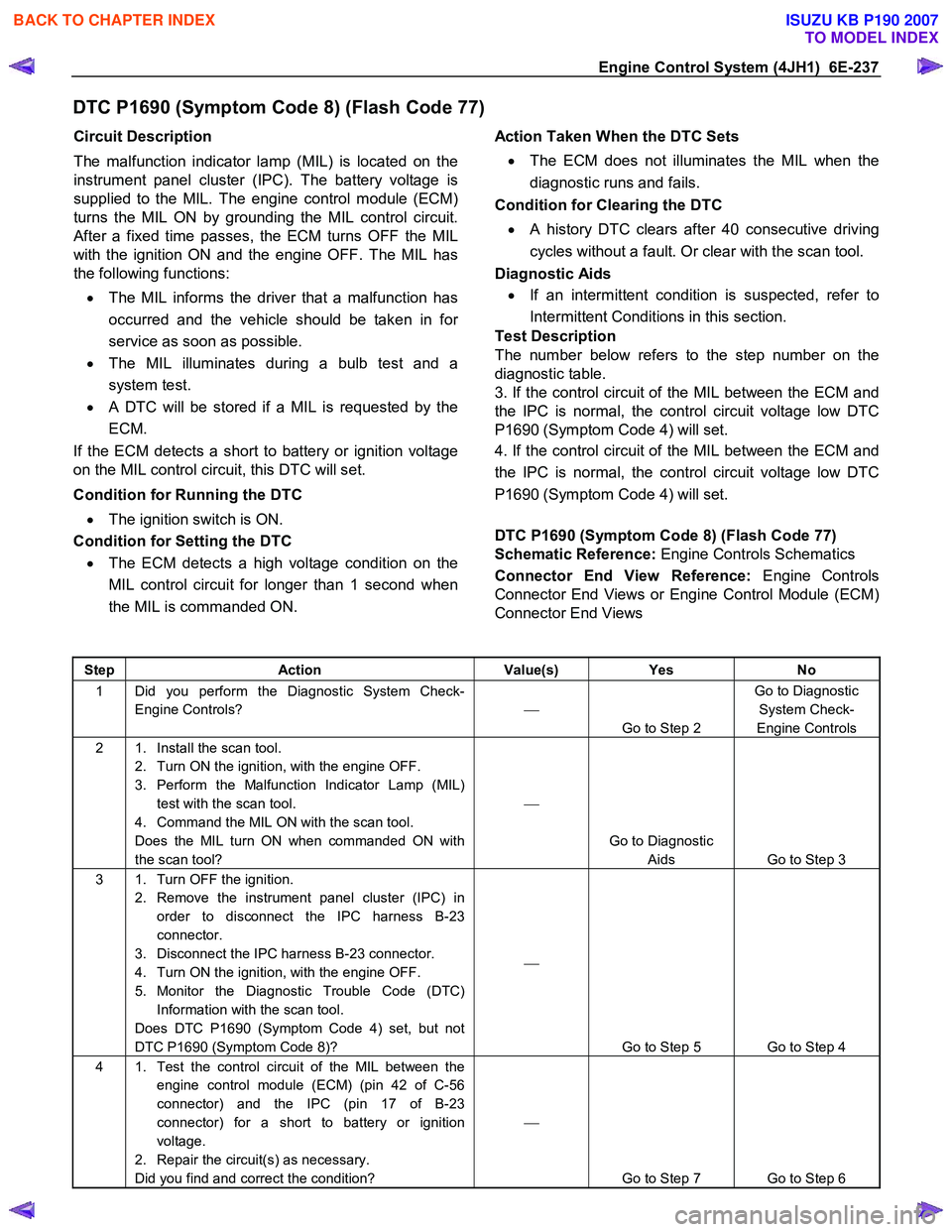
DTC P1690 (Symptom Code 8) (Flash Code 77)
Circuit Description
The malfunction indicator lamp (MIL) is located on the
instrument panel cluster (IPC). The battery voltage is
supplied to the MIL. The engine control module (ECM)
turns the MIL ON by grounding the MIL control circuit.
After a fixed time passes, the ECM turns OFF the MIL
with the ignition ON and the engine OFF. The MIL has
the following functions:
• The MIL informs the driver that a malfunction has
occurred and the vehicle should be taken in fo
r
service as soon as possible.
• The MIL illuminates during a bulb test and a
system test.
•
A DTC will be stored if a MIL is requested by the
ECM.
If the ECM detects a short to battery or ignition voltage
on the MIL control circuit, this DTC will set.
Condition for Running the DTC • The ignition switch is ON.
Condition for Setting the DTC
• The ECM detects a high voltage condition on the
MIL control circuit for longer than 1 second when
the MIL is commanded ON.
Action Taken When the DTC Sets
• The ECM does not illuminates the MIL when the
diagnostic runs and fails.
Condition for Clearing the DTC
• A history DTC clears after 40 consecutive driving
cycles without a fault. Or clear with the scan tool.
Diagnostic Aids
• If an intermittent condition is suspected, refer to
Intermittent Conditions in this section.
Test Description
The number below refers to the step number on the
diagnostic table.
3. If the control circuit of the MIL between the ECM and
the IPC is normal, the control circuit voltage low DTC
P1690 (Symptom Code 4) will set.
4. If the control circuit of the MIL between the ECM and
the IPC is normal, the control circuit voltage low DTC
P1690 (Symptom Code 4) will set.
DTC P1690 (Symptom Code 8) (Flash Code 77)
Schematic Reference: Engine Controls Schematics
Connector End View Reference: Engine Controls
Connector End Views or Engine Control Module (ECM)
Connector End Views
Step Action Value(s) Yes No
1 Did you perform the Diagnostic System Check-
Engine Controls?
Go to Step 2 Go to Diagnostic
System Check-
Engine Controls
2 1. Install the scan tool. 2. Turn ON the ignition, with the engine OFF.
3. Perform the Malfunction Indicator Lamp (MIL) test with the scan tool.
4. Command the MIL ON with the scan tool.
Does the MIL turn ON when commanded ON with
the scan tool?
Go to Diagnostic Aids Go to Step 3
3 1. Turn OFF the ignition. 2. Remove the instrument panel cluster (IPC) in order to disconnect the IPC harness B-23
connector.
3. Disconnect the IPC harness B-23 connector.
4. Turn ON the ignition, with the engine OFF.
5. Monitor the Diagnostic Trouble Code (DTC) Information with the scan tool.
Does DTC P1690 (Symptom Code 4) set, but not
DTC P1690 (Symptom Code 8)?
Go to Step 5 Go to Step 4
4 1. Test the control circuit of the MIL between the engine control module (ECM) (pin 42 of C-56
connector) and the IPC (pin 17 of B-23
connector) for a short to battery or ignition
voltage.
2. Repair the circuit(s) as necessary.
Did you find and correct the condition?
Go to Step 7 Go to Step 6
BACK TO CHAPTER INDEX
TO MODEL INDEX
ISUZU KB P190 2007
Page 1273 of 6020
Engine Control System (4JH1) 6E-239
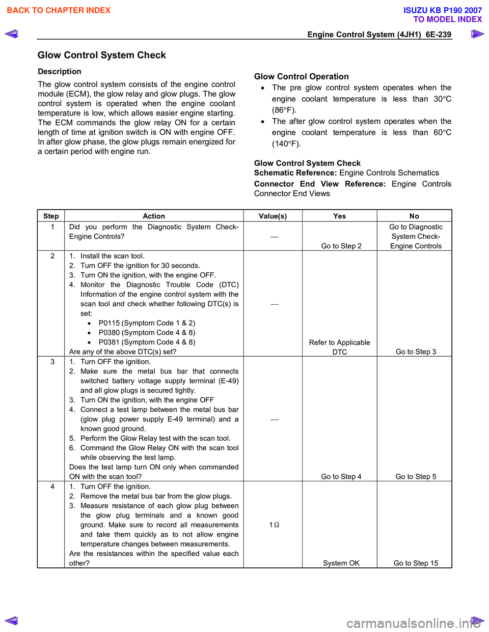
Glow Control System Check
Description
The glow control system consists of the engine control
module (ECM), the glow relay and glow plugs. The glo
w
control system is operated when the engine coolant
temperature is low, which allows easier engine starting.
The ECM commands the glow relay ON for a certain
length of time at ignition switch is ON with engine OFF.
In after glow phase, the glow plugs remain energized fo
r
a certain period with engine run.
Glow Control Operation
•
The pre glow control system operates when the
engine coolant temperature is less than 30 °C
(86 °F).
• The after glow control system operates when the
engine coolant temperature is less than 60 °C
(140 °F).
Glow Control System Check
Schematic Reference: Engine Controls Schematics
Connector End View Reference: Engine Controls
Connector End Views
Step Action Value(s) Yes No
1 Did you perform the Diagnostic System Check-
Engine Controls?
Go to Step 2 Go to Diagnostic
System Check-
Engine Controls
2 1. Install the scan tool. 2. Turn OFF the ignition for 30 seconds.
3. Turn ON the ignition, with the engine OFF.
4. Monitor the Diagnostic Trouble Code (DTC) Information of the engine control system with the
scan tool and check whether following DTC(s) is
set: • P0115 (Symptom Code 1 & 2)
• P0380 (Symptom Code 4 & 8)
• P0381 (Symptom Code 4 & 8)
Are any of the above DTC(s) set?
Refer to Applicable DTC Go to Step 3
3 1. Turn OFF the ignition.
2. Make sure the metal bus bar that connects switched battery voltage supply terminal (E-49)
and all glow plugs is secured tightly.
3. Turn ON the ignition, with the engine OFF
4. Connect a test lamp between the metal bus bar (glow plug power supply E-49 terminal) and a
known good ground.
5. Perform the Glow Relay test with the scan tool.
6. Command the Glow Relay ON with the scan tool while observing the test lamp.
Does the test lamp turn ON only when commanded
ON with the scan tool?
Go to Step 4 Go to Step 5
4 1. Turn OFF the ignition. 2. Remove the metal bus bar from the glow plugs.
3. Measure resistance of each glow plug between the glow plug terminals and a known good
ground. Make sure to record all measurements
and take them quickly as to not allow engine
temperature changes between measurements.
Are the resistances within the specified value each
other? 1
Ω
System OK Go to Step 15
BACK TO CHAPTER INDEX
TO MODEL INDEX
ISUZU KB P190 2007
Page 1276 of 6020
6E-242 Engine Control System (4JH1)
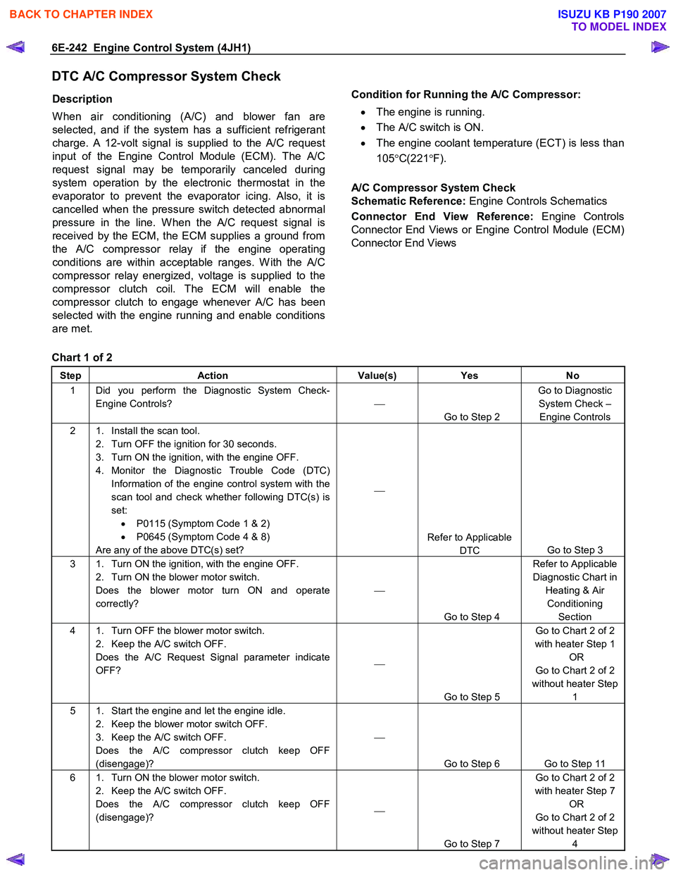
DTC A/C Compressor System Check
Description
W hen air conditioning (A/C) and blower fan are
selected, and if the system has a sufficient refrigerant
charge. A 12-volt signal is supplied to the A/C request
input of the Engine Control Module (ECM). The A/C
request signal may be temporarily canceled during
system operation by the electronic thermostat in the
evaporator to prevent the evaporator icing. Also, it is
cancelled when the pressure switch detected abnormal
pressure in the line. W hen the A/C request signal is
received by the ECM, the ECM supplies a ground from
the A/C compressor relay if the engine operating
conditions are within acceptable ranges. W ith the A/C
compressor relay energized, voltage is supplied to the
compressor clutch coil. The ECM will enable the
compressor clutch to engage whenever A/C has been
selected with the engine running and enable conditions
are met.
Condition for Running the A/C Compressor:
• The engine is running.
• The A/C switch is ON.
• The engine coolant temperature (ECT) is less than
105 °C(221 °F).
A/C Compressor System Check
Schematic Reference: Engine Controls Schematics
Connector End View Reference: Engine Controls
Connector End Views or Engine Control Module (ECM)
Connector End Views
Chart 1 of 2
Step Action Value(s) Yes No
1 Did you perform the Diagnostic System Check-
Engine Controls?
Go to Step 2 Go to Diagnostic
System Check – Engine Controls
2 1. Install the scan tool. 2. Turn OFF the ignition for 30 seconds.
3. Turn ON the ignition, with the engine OFF.
4. Monitor the Diagnostic Trouble Code (DTC) Information of the engine control system with the
scan tool and check whether following DTC(s) is
set: • P0115 (Symptom Code 1 & 2)
• P0645 (Symptom Code 4 & 8)
Are any of the above DTC(s) set?
Refer to Applicable DTC Go to Step 3
3 1. Turn ON the ignition, with the engine OFF.
2. Turn ON the blower motor switch.
Does the blower motor turn ON and operate
correctly?
Go to Step 4 Refer to Applicable
Diagnostic Chart in Heating & Air Conditioning Section
4 1. Turn OFF the blower motor switch. 2. Keep the A/C switch OFF.
Does the A/C Request Signal parameter indicate
OFF?
Go to Step 5 Go to Chart 2 of 2
with heater Step 1 OR
Go to Chart 2 of 2
without heater Step 1
5 1. Start the engine and let the engine idle. 2. Keep the blower motor switch OFF.
3. Keep the A/C switch OFF.
Does the A/C compressor clutch keep OFF
(disengage)?
Go to Step 6 Go to Step 11
6 1. Turn ON the blower motor switch. 2. Keep the A/C switch OFF.
Does the A/C compressor clutch keep OFF
(disengage)?
Go to Step 7 Go to Chart 2 of 2
with heater Step 7 OR
Go to Chart 2 of 2
without heater Step 4
BACK TO CHAPTER INDEX
TO MODEL INDEX
ISUZU KB P190 2007
Page 1289 of 6020
Engine Control System (4JH1) 6E-255
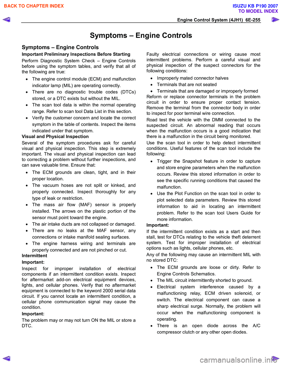
Symptoms – Engine Controls
Symptoms – Engine Controls
Important Preliminary Inspections Before Starting
Perform Diagnostic System Check – Engine Controls
before using the symptom tables, and verify that all o
f
the following are true:
• The engine control module (ECM) and malfunction
indicator lamp (MIL) are operating correctly.
• There are no diagnostic trouble codes (DTCs)
stored, or a DTC exists but without the MIL.
• The scan tool data is within the normal operating
range. Refer to scan tool Data List in this section.
• Verify the customer concern and locate the correct
symptom in the table of contents. Inspect the items
indicated under that symptom.
Visual and Physical Inspection
Several of the symptom procedures ask for careful
visual and physical inspection. This step is extremel
y
important. The visual and physical inspection can lead
to correcting a problem without further inspections, and
can save valuable time. Ensure that:
• The ECM grounds are clean, tight, and in thei
r
proper location.
• The vacuum hoses are not split or kinked, and
properly connected. Inspect thoroughly for an
y
type of leak or restriction.
• The mass air flow (MAF) sensor is properl
y
installed. The arrows on the plastic portion of the
sensor must point toward the engine.
• The air intake ducts are not collapsed or damaged.
• There are no leaks at the MAF sensor, an
y
connections or intake manifold sealing surfaces.
• The engine harness wiring and terminals are
properly connected and are not pinched or cut.
Intermittent
Important:
Inspect for improper installation of electrical
components if an intermittent condition exists. Inspect
for aftermarket add-on electrical equipment devices,
lights, and cellular phones. Verify that no aftermarket
equipment is connected to the keyword 2000 serial data
circuit. If you cannot locate an intermittent condition, a
cellular phone communication signal may cause the
condition.
Important:
The problem may or may not turn ON the MIL or store a
DTC.
Faulty electrical connections or wiring cause most
intermittent problems. Perform a careful visual and
physical inspection of the suspect connectors for the
following conditions:
• Improperly mated connector halves
• Terminals that are not seated
• Terminals that are damaged or improperly formed
Reform or replace connector terminals in the problem
circuit in order to ensure proper contact tension.
Remove the terminal from the connector body in orde
r
to inspect for poor terminal wire connection.
Road test the vehicle with the DMM connected to the
suspected circuit. An abnormal reading that occurs
when the malfunction occurs is a good indication that
there is a malfunction in the circuit being monitored.
Use the scan tool in order to help detect intermittent
conditions. Useful features of the scan tool include the
following:
• Trigger the Snapshot feature in order to capture
and store engine parameters when the malfunction
occurs. Review this stored information in order to
see the specific running conditions that caused the
malfunction.
• Use the Plot Function on the scan tool in order to
plot selected data parameters. Review this stored
information to aid in locating an intermittent
problem. Refer to the scan tool Users Guide fo
r
more information.
Important:
If the intermittent condition exists as a start and then
stall, test for DTCs relating to the vehicle theft deterrent
system. Test for improper installation of electrical
options such as lights, cellular phones, etc.
Any of the following may cause an intermittent MIL with
no stored DTC:
• The ECM grounds are loose or dirty. Refer to
Engine Controls Schematics.
• The MIL circuit intermittently shorted to ground.
• Electrical system interference caused by a
malfunctioning relay, ECM driven solenoid, o
r
switch. The electrical component can cause a
sharp electrical surge. Normally, the problem will
occur when the malfunctioning component is
operating.
• There is an open diode across the A/C
compressor clutch or any other open diodes.
BACK TO CHAPTER INDEX
TO MODEL INDEX
ISUZU KB P190 2007
Page 1290 of 6020
6E-256 Engine Control System (4JH1)
Important:
The following symptom tables contain groups o
f
possible causes for each symptom. The order of these
procedures is not important. If the scan tool readings do
not indicate the problems, then proceed in a logical
order, easiest to check or most likely to cause first. In
order to determine if a specific vehicle is using a
particular system or component, refer to Engine
Controls Schematics for an application.
Use the following tables when diagnosing a symptom
complaint:
• Intermittent Conditions
• Hard Start
• Rough, Unstable, or Incorrect Idle and Stalling
• Cuts Out, Misses
• Surge/Chuggles
• Lack of Power, Sluggishness, or Sponginess
• Hesitation, Sag, Stumble
• Fuel Knock/Combustion Noise
• Poor Fuel Economy
• Excessive Smoke (Black Smoke)
• Excessive Smoke (W hite Smoke)
Intermittent Conditions
Checks Action
DEFINITION:The problem is not currently present but is indicated in DTC History.
OR
There is a customer complaint, but the symptom cannot currently be duplicated, if the problem is not DTC related.
Preliminary Checks • Refer to Symptoms – Engine Controls before starting.
Harness/Connector Many intermittent open or shorted circuits are affected by harness/connector
movement that is caused by vibration, engine torque, bumps/rough pavement, etc.
Test for this type of condition by performing the applicable procedure from the
following list:
• Move related connectors and wiring while monitoring the appropriate scan tool data.
• Move related connectors and wiring with the component commanded ON, and OFF,
with the scan tool. Observe the component operation.
• W ith the engine running, move related connectors and wiring while monitoring
engine operation.
If harness or connector movement affects the data displayed, component/system
operation, or engine operation, inspect and repair the harness/connections as
necessary.
Refer to Electrical Connections or W iring.
BACK TO CHAPTER INDEX
TO MODEL INDEX
ISUZU KB P190 2007
Page 1292 of 6020
6E-258 Engine Control System (4JH1)
Checks Action
Electromagnetic Interference (EMI)
and Electrical Noise Some electrical components/circuits are sensitive to EMI or other types of electrical
noise. Inspect for the following conditions:
• A misrouted harness that is too close to high voltage/high current devices such as
injection components, motors, generator etc. These components may induce
electrical noise on a circuit that could interfere with normal circuit operation.
• Electrical system interference caused by a malfunctioning relay, or the engine control
module (ECM) driven solenoid or switch. These conditions can cause a sharp
electrical surge. Normally, the problem will occur when the malfunctioning
component is operating.
• Improper installation of non-factory or aftermarket add on accessories such as lights,
2-way radios, amplifiers, electric motors, remote starters, alarm systems, cell
phones, etc. These accessories may lead to an emission related failure while in use,
but do not fail when the accessories are not in use.
• Test for an open diode across the A/C compressor clutch and for other open diodes.
Some relays may contain a clamping diode.
• Test the generator for a bad rectifier bridge that may be allowing AC noise into the
electrical system.
Incorrect ECM Programming • There are only a few situations where reprogramming a ECM is appropriate:
Important:
DO NOT reprogram the ECM with the SAME software/calibration files that are already
present in the ECM. This is not an effective repair for any type of driveability problem. - A ECM from another vehicle is installed.
- Revised software/calibration files have been released for this vehicle.
• Verify that the ECM contains the correct software/calibration. If incorrect
programming is found, reprogram the ECM with the most current
software/calibration.
Duplicating Failure Conditions • If none of the previous tests are successful, attempt to duplicate and/or capture the
failure conditions.
• An alternate method is to drive the vehicle with the DMM connected to a suspected
circuit. An abnormal reading on the DMM when the problem occurs, may help you
locate the problem.
scan tool Snapshot The scan tool can be set up to take a Snapshot of the parameters available via serial
data. The Snapshot function records live data over a period of time. The recorded data
can be played back and analyzed. The scan tool can also graph parameters singly or
in combinations of parameters for comparison. The Snapshot can be triggered
manually at the time the symptom is noticed, or set up in advance to trigger when a
DTC sets.
An abnormal value captured in the recorded data may point to a system or component
that needs to be investigated further.
Refer to the scan tool user instructions for more information on the Snapshot function.
Hard Start
Checks Action
DEFINITION:The engine cranks OK, but does not start for a long time. The engine does eventually run, or may start but
immediately dies.
Preliminary Checks •
Diagnostic System Check - Engine Controls.
• Ensure the driver is using the correct starting procedure.
• Inspect the engine control module (ECM) and fuel injection pump control unit (PCU)
grounds for being clean, tight, and in their proper locations.
• Inspect that the harness connectors are correctly connected.
• Inspect the fuel type and quality.
• Inspect the scan tool Data List in this section.
• Inspect the Service Bulletins for ECM software updates.
BACK TO CHAPTER INDEX
TO MODEL INDEX
ISUZU KB P190 2007
Page 1312 of 6020
6E-278 Engine Control System (4JH1)
• Destination Code
j. Select Next.
k. Verify your selection on the Summary screen.
Important:
Refer to Service Bulletins before service programming is
performed if the bulletins are listed along with the
calibration files.
Important:
Select Cancel if you receive a message stating that the
calibration selected is already the current calibration in
the ECM and reprogramming with the same download is
not allowed.
l. Select Reprog.
m. The Transfer Data screen will appear until the progress bar reaches 100%.
6. Close the application and return to the TIS application selection screen after the download is
complete.
7. Turn OFF the scan tool.
8. Disconnect the scan tool from the terminal.
9. Transfer the data from the scan tool to the ECM using the following procedure:
a. Connect the scan tool to the vehicle DLC, with the engine and the scan tool OFF.
b. Turn ON the scan tool.
c. Press Enter at the Title screen.
d. Turn ON the ignition, with the engine OFF.
e. Select Service Programming System.
f. Select the Program ECU on the scan tool.
g. Follow the on-screen instructions and select Continue.
h. Programming in Process will appear until the progress bar reaches 100%.
Important:
The vehicle fitted with automatic transmission, Check
Trans lamp may blink while programming the ECM since
communication between the ECM and TCM is
interrupted. Clear DTC in any module afte
r
programming.
i. Select Continue and exit the program after the scan tool displays Programming W as
Successful.
10. Turn OFF the ignition.
11. Turn OFF the scan tool.
12. Disconnect the scan tool from the vehicle.
Service Programming System (SPS) (Pass-
Thru Procedure)
Pass-Thru programming allows the scan tool to remain
connected to the terminal and to the vehicle throughou
t
the programming process. The vehicle must be in close
proximity to the terminal while using Pass-Thru.
Important:
The TIS supports service programming with the scan
tool scan tool only.
1. Launch the TIS application at the terminal.
2. Select the Service Programming System at the main screen.
3. Highlight the following information on the Selec
t
Diagnostic Tool and Programming Process screen:
• Select Diagnostic Tool-Select Pass-Thru
• Select Programming Process-Identify whethe
r
as existing engine control module (ECM) is
being reprogrammed or an ECM is being
replaced with a new one.
• Select ECU Location-Select Vehicle.
4. Select Next.
5. Complete all vehicle data on the Preparing fo
r
Communication/Determine Vehicle screen until
Next is highlighted.
6. Select Next.
7. Follow the instruction on the Preparing fo
r
Communication screen.
Important:
In order to reduce the potential for signal loss, the RS-
232 cable should not be more than 25 feet long.
8. Select Next.
9. Verify the VIN on the Validate Vehicle Identification Number (VIN) screen and select Next.
Important:
If the ECM is replaced to new one, VIN does no
t
displayed. Input correct VIN reading from stamped VIN
or affixed VIN plate on the vehicle. If the ECM from
another vehicle is installed, input correct VIN by same
way. 10. Highlight Engine on the System Type screen and
select Next, if requested.
11. Complete the following information based on the service ID plate on the Validate Vehicle Data
screen until Next is highlighted:
• Model
• Model Year
• Engine
• Type of Transmission
• Destination Code
12. Select Next.
13. Verify your selection on the Summary screen.
BACK TO CHAPTER INDEX
TO MODEL INDEX
ISUZU KB P190 2007
Page 1313 of 6020
Engine Control System (4JH1) 6E-279
Important:
Refer to Service Bulletins before service programming is
performed if the bulletins are listed along with the
calibration files.
Important:
Select Cancel if you receive a message stating that the
calibration selected is already the current calibration in
the scan tool and reprogramming with the same
download is not allowed.
14. Select Reprog.
15. The Transfer Data screen will appear until the progress bar reaches 100%.
Important:
The vehicle fitted with automatic transmission, Check
Trans lamp may blink while programming the ECM since
communication between the ECM and TCM is
interrupted. Clear DTC in any module afte
r
programming. 16. Select Close on the Programming Complete
screen.
17. Turn OFF the scan tool.
18. Disconnect the scan tool from the vehicle.
Accelerator Pedal Position (APP) Sensor
Replacement
Removal Procedure 1. Disconnect the negative battery cable.
2. Disconnect the APP sensor connector.
3. Loosen two screws and remove APP sensor from the throttle body.
Installation Procedure 1. Temporary tighten the APP sensor by two screws. 2. Connect a APP sensor connectors to the
APP
sensor.
3. Connect the Tech2 to the vehicle.
4. Connect the negative battery cable.
5. Select "Data Display" with the Tech2.
6. Check the APP sensor data and adjust the
APP
sensor.
7. Tighten two screws.
Crankshaft Position (CKP) Sensor
Replacement
Removal Procedure
1. Disconnect the negative battery cable.
2. Disconnect connector from the CKP sensor.
3. Loosen a bolt and remove the CKP sensor from the clutch housing.
Installation Procedure
1. Install the CKP sensor to the clutch housing.
2. Tighten CKP sensor by a bolt with specified tightening torque.
Tightening Torque
• Bolts: 8.0 - 12.0 N.m (0.8 - 1.2 kgf.m)
3. Connect a CKP sensor connector to the CKP sensor.
4. Connect the negative battery cable.
BACK TO CHAPTER INDEX
TO MODEL INDEX
ISUZU KB P190 2007