2007 ISUZU KB P190 oil viscosity
[x] Cancel search: oil viscosityPage 2091 of 6020
ENGINE MECHANICAL (C24SE) 6A-77
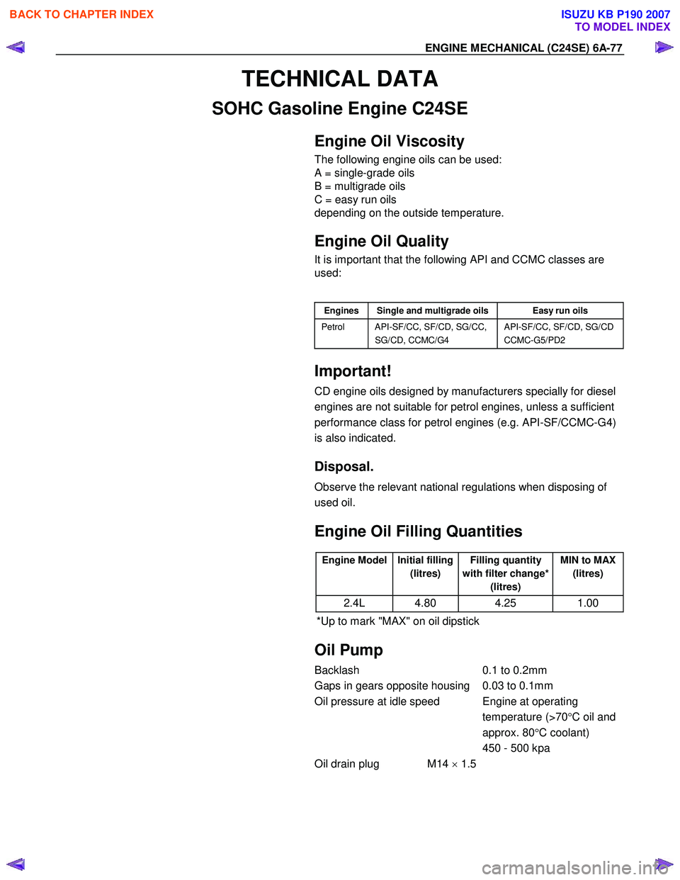
TECHNICAL DATA
SOHC Gasoline Engine C24SE
Engine Oil Viscosity
The following engine oils can be used:
A = single-grade oils
B = multigrade oils
C = easy run oils
depending on the outside temperature.
Engine Oil Quality
It is important that the following API and CCMC classes are
used:
Engines Single and multigrade oils Easy run oils
Petrol API-SF/CC, SF/CD, SG/CC,
SG/CD, CCMC/G4 API-SF/CC, SF/CD, SG/CD
CCMC-G5/PD2
Important!
CD engine oils designed by manufacturers specially for diesel
engines are not suitable for petrol engines, unless a sufficient
performance class for petrol engines (e.g. API-SF/CCMC-G4)
is also indicated.
Disposal.
Observe the relevant national regulations when disposing of
used oil.
Engine Oil Filling Quantities
Engine Model Initial filling
(litres) Filling quantity
with filter change* (litres) MIN to MAX
(litres)
2.4L 4.80 4.25 1.00
*Up to mark "MAX" on oil dipstick
Oil Pump
Backlash 0.1 to 0.2mm
Gaps in gears opposite housing 0.03 to 0.1mm
Oil pressure at idle speed Engine at operating temperature (>70°C oil and
approx. 80 °C coolant)
450 - 500 kpa
Oil drain plug M14 × 1.5
BACK TO CHAPTER INDEX
TO MODEL INDEX
ISUZU KB P190 2007
Page 2237 of 6020
ENGINE DRIVEABILITY AND EMISSIONS 6E–67
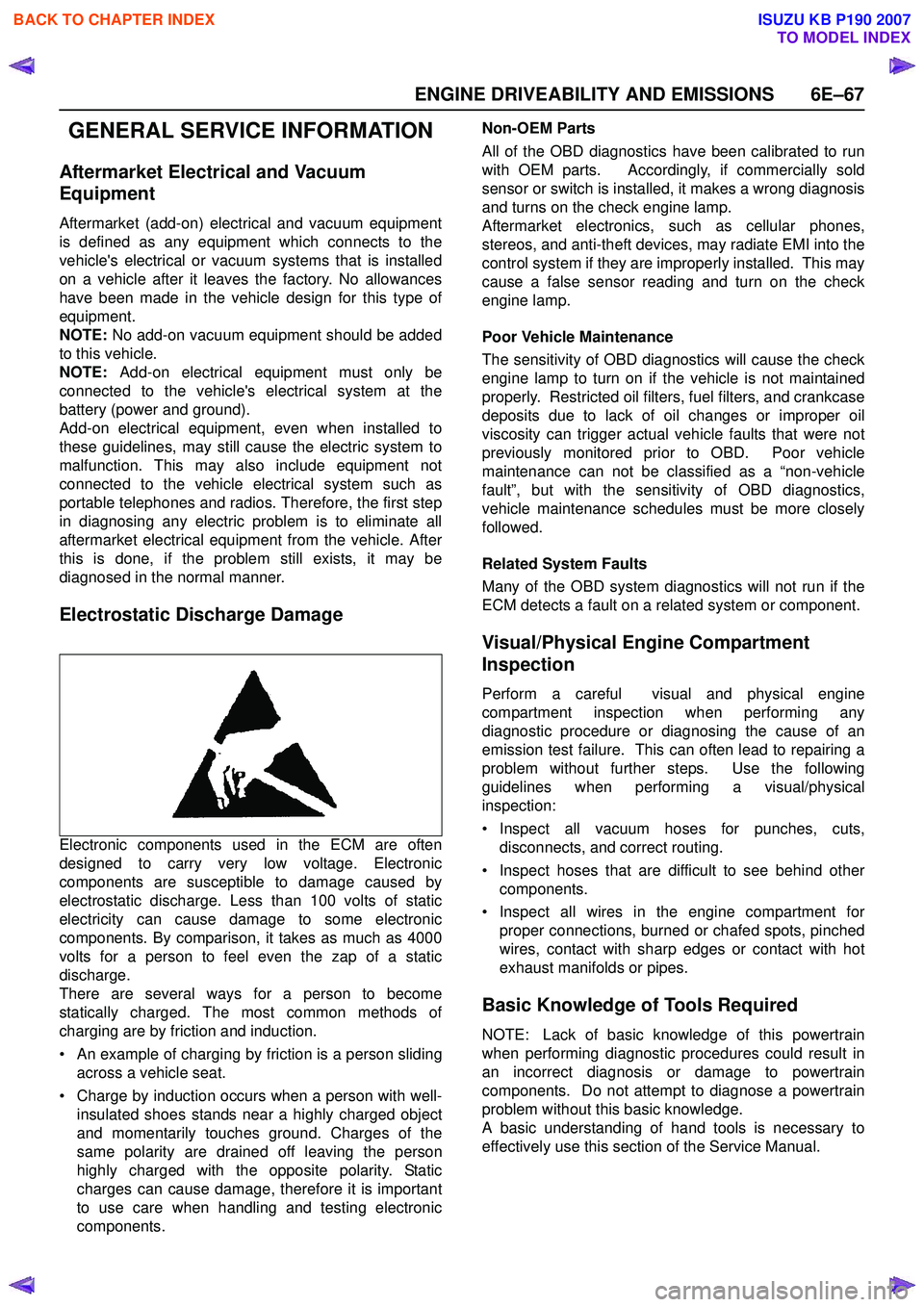
GENERAL SERVICE INFORMATION
Aftermarket Electrical and Vacuum
Equipment
Aftermarket (add-on) electrical and vacuum equipment
is defined as any equipment which connects to the
vehicle's electrical or vacuum systems that is installed
on a vehicle after it leaves the factory. No allowances
have been made in the vehicle design for this type of
equipment.
NOTE: No add-on vacuum equipment should be added
to this vehicle.
NOTE: Add-on electrical equipment must only be
connected to the vehicle's electrical system at the
battery (power and ground).
Add-on electrical equipment, even when installed to
these guidelines, may still cause the electric system to
malfunction. This may also include equipment not
connected to the vehicle electrical system such as
portable telephones and radios. Therefore, the first step
in diagnosing any electric problem is to eliminate all
aftermarket electrical equipment from the vehicle. After
this is done, if the problem still exists, it may be
diagnosed in the normal manner.
Electrostatic Discharge Damage
Electronic components used in the ECM are often
designed to carry very low voltage. Electronic
components are susceptible to damage caused by
electrostatic discharge. Less than 100 volts of static
electricity can cause damage to some electronic
components. By comparison, it takes as much as 4000
volts for a person to feel even the zap of a static
discharge.
There are several ways for a person to become
statically charged. The most common methods of
charging are by friction and induction.
• An example of charging by friction is a person sliding across a vehicle seat.
• Charge by induction occurs when a person with well- insulated shoes stands near a highly charged object
and momentarily touches ground. Charges of the
same polarity are drained off leaving the person
highly charged with the opposite polarity. Static
charges can cause damage, therefore it is important
to use care when handling and testing electronic
components. Non-OEM Parts
All of the OBD diagnostics have been calibrated to run
with OEM parts. Accordingly, if commercially sold
sensor or switch is installed, it makes a wrong diagnosis
and turns on the check engine lamp.
Aftermarket electronics, such as cellular phones,
stereos, and anti-theft devices, may radiate EMI into the
control system if they are improperly installed. This may
cause a false sensor reading and turn on the check
engine lamp.
Poor Vehicle Maintenance
The sensitivity of OBD diagnostics will cause the check
engine lamp to turn on if the vehicle is not maintained
properly. Restricted oil filters, fuel filters, and crankcase
deposits due to lack of oil changes or improper oil
viscosity can trigger actual vehicle faults that were not
previously monitored prior to OBD. Poor vehicle
maintenance can not be classified as a “non-vehicle
fault”, but with the sensitivity of OBD diagnostics,
vehicle maintenance schedules must be more closely
followed.
Related System Faults
Many of the OBD system diagnostics will not run if the
ECM detects a fault on a related system or component.
Visual/Physical Engine Compartment
Inspection
Perform a careful visual and physical engine
compartment inspection when performing any
diagnostic procedure or diagnosing the cause of an
emission test failure. This can often lead to repairing a
problem without further steps. Use the following
guidelines when performing a visual/physical
inspection:
• Inspect all vacuum hoses for punches, cuts, disconnects, and correct routing.
• Inspect hoses that are difficult to see behind other components.
• Inspect all wires in the engine compartment for proper connections, burned or chafed spots, pinched
wires, contact with sharp edges or contact with hot
exhaust manifolds or pipes.
Basic Knowledge of Tools Required
NOTE: Lack of basic knowledge of this powertrain
when performing diagnostic procedures could result in
an incorrect diagnosis or damage to powertrain
components. Do not attempt to diagnose a powertrain
problem without this basic knowledge.
A basic understanding of hand tools is necessary to
effectively use this section of the Service Manual.
BACK TO CHAPTER INDEX
TO MODEL INDEX
ISUZU KB P190 2007
Page 2507 of 6020
Engine Mechanical – V6 Page 6A1–28
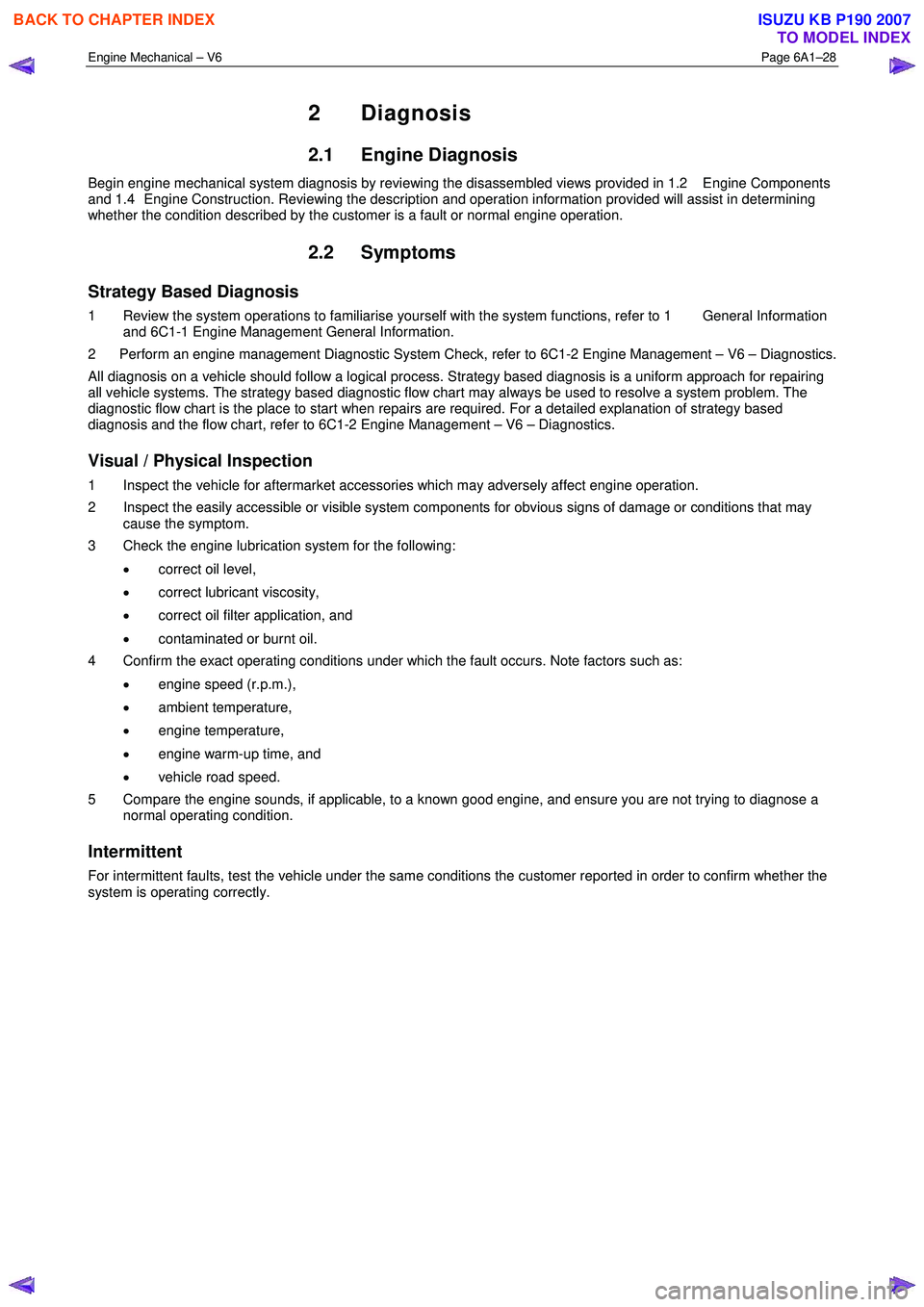
2 Diagnosis
2.1 Engine Diagnosis
Begin engine mechanical system diagnosis by reviewing the disassembled views provided in 1.2 Engine Components
and 1.4 Engine Construction. Reviewing the description and operation information provided will assist in determining
whether the condition described by the customer is a fault or normal engine operation.
2.2 Symptoms
Strategy Based Diagnosis
1 Review the system operations to familiarise yourself with the system functions, refer to 1 General Information and 6C1-1 Engine Management General Information.
2 Perform an engine management Diagnostic System Check, refer to 6C1-2 Engine Management – V6 – Diagnostics.
All diagnosis on a vehicle should follow a logical process. Strategy based diagnosis is a uniform approach for repairing
all vehicle systems. The strategy based diagnostic flow chart may always be used to resolve a system problem. The
diagnostic flow chart is the place to start when repairs are required. For a detailed explanation of strategy based
diagnosis and the flow chart, refer to 6C1-2 Engine Management – V6 – Diagnostics.
Visual / Physical Inspection
1 Inspect the vehicle for aftermarket accessories which may adversely affect engine operation.
2 Inspect the easily accessible or visible system components for obvious signs of damage or conditions that may cause the symptom.
3 Check the engine lubrication system for the following:
• correct oil level,
• correct lubricant viscosity,
• correct oil filter application, and
• contaminated or burnt oil.
4 Confirm the exact operating conditions under which the fault occurs. Note factors such as:
• engine speed (r.p.m.),
• ambient temperature,
• engine temperature,
• engine warm-up time, and
• vehicle road speed.
5 Compare the engine sounds, if applicable, to a known good engine, and ensure you are not trying to diagnose a normal operating condition.
Intermittent
For intermittent faults, test the vehicle under the same conditions the customer reported in order to confirm whether the
system is operating correctly.
BACK TO CHAPTER INDEX
TO MODEL INDEX
ISUZU KB P190 2007
Page 2511 of 6020
Engine Mechanical – V6 Page 6A1–32
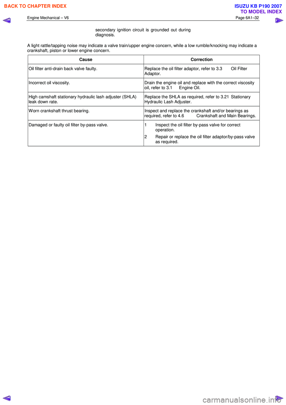
secondary ignition circuit is grounded out during
diagnosis.
A light rattle/tapping noise may indicate a valve train/upper engine concern, while a low rumble/knocking may indicate a
crankshaft, piston or lower engine concern.
Cause Correction
Oil filter anti-drain back valve faulty. Replace the oil filter adaptor, refer to 3.3 Oil Filter
Adaptor.
Incorrect oil viscosity. Drain the engine oil and replace with the correct viscosity
oil, refer to 3.1 Engine Oil.
High camshaft stationary hydraulic lash adjuster (SHLA)
leak down rate. Replace the SHLA as required, refer to 3.21 Stationary
Hydraulic Lash Adjuster.
W orn crankshaft thrust bearing. Inspect and replace the crankshaft and/or bearings as
required, refer to 4.6 Crankshaft and Main Bearings.
Damaged or faulty oil filter by-pass valve. 1 Inspect the oil filter by-pass valve for correct
operation.
2 Repair or replace the oil filter adaptor/by-pass valve as required.
BACK TO CHAPTER INDEX
TO MODEL INDEX
ISUZU KB P190 2007
Page 2518 of 6020

Engine Mechanical – V6 Page 6A1–39
2.16 Cylinder Leakage Test
A leakage test may be performed to measure cylinder/combustion chamber leakage. High cylinder leakage may indicate
one or more of the following:
• worn or burnt valves,
• broken valve springs,
• stuck valve lifters,
• incorrect valve lash/adjustment,
• damaged piston,
• worn piston rings,
• worn or scored cylinder bore,
• damaged cylinder head gasket,
• cracked or damaged cylinder head, or
• cracked or damaged engine block.
1 Disconnect the battery ground negative cable.
2 Remove the spark plugs from all cylinders, refer to 6C1-3 Engine Management – V6 – Service Operations.
3 Rotate the crankshaft to place the piston in the cylinder being tested at top dead centre (TDC) of the compression stroke.
4 Install a commercially available cylinder head leak down tester into the spark plug hole.
NOTE
If required, hold the crankshaft balancer bolt to
prevent the engine from rotating.
5 Apply shop air pressure to the cylinder head leak down tester and adjust according to the manufacturers instructions.
6 Record the cylinder leakage value. Cylinder leakage that exceeds 25 percent is considered excessive and may require component service. In excessive leakage situations, inspect for the following conditions:
• air leakage sounds at the throttle body or air inlet duct that may indicate a worn or burnt intake valve or a
broken valve spring,
• air leakage sounds at the exhaust system tailpipe that may indicate a worn or burnt exhaust valve or a broken
valve spring,
• air leakage sounds from the crankcase, oil level indicator tube, or oil fill tube that may indicate worn piston
rings, a damaged piston, a worn or scored cylinder bore, a damaged engine block or a damaged cylinder
head, or
• air bubbles in the cooling system may indicate a damaged cylinder head or a damaged cylinder head gasket.
7 Perform the leakage test on the remaining cylinders and record the values.
2.17 Engine Oil Consumption Diagnosis
Definition
Excessive oil consumption (not due to leaks) is the use of 3 litres or more of engine oil within 10,000 kilometres. Prior to
performing oil pressure testing, a preliminary inspection of the vehicle should be performed. During the preliminary visual
inspection, the following likely causes of excessive oil usage should be investigated.
Cause Correction
External oil leaks. Refer to 2.18 Engine Oil Leak Diagnosis.
Incorrect oil level or reading of the oil level indicator. Check for the correct oil level, refer to 3.1 Engine Oil.
Incorrect oil viscosity. Replace the engine oil, using the recommended SAE grade
of engine oil, refer to 3.1 Engine Oil.
Continuous high-speed driving or severe usage. Service vehicle more frequently, refer to 0B Lubrication and
Service.
Crankcase ventilation system restricted or malfunctioning. Repair or replace crankcase ventilation system components as required, refer to 6C1-3 Engine Management – V6 –
Service Operations.
BACK TO CHAPTER INDEX
TO MODEL INDEX
ISUZU KB P190 2007
Page 2808 of 6020
Engine Mechanical – V6 Page 6A1–31
Page 6A1–31
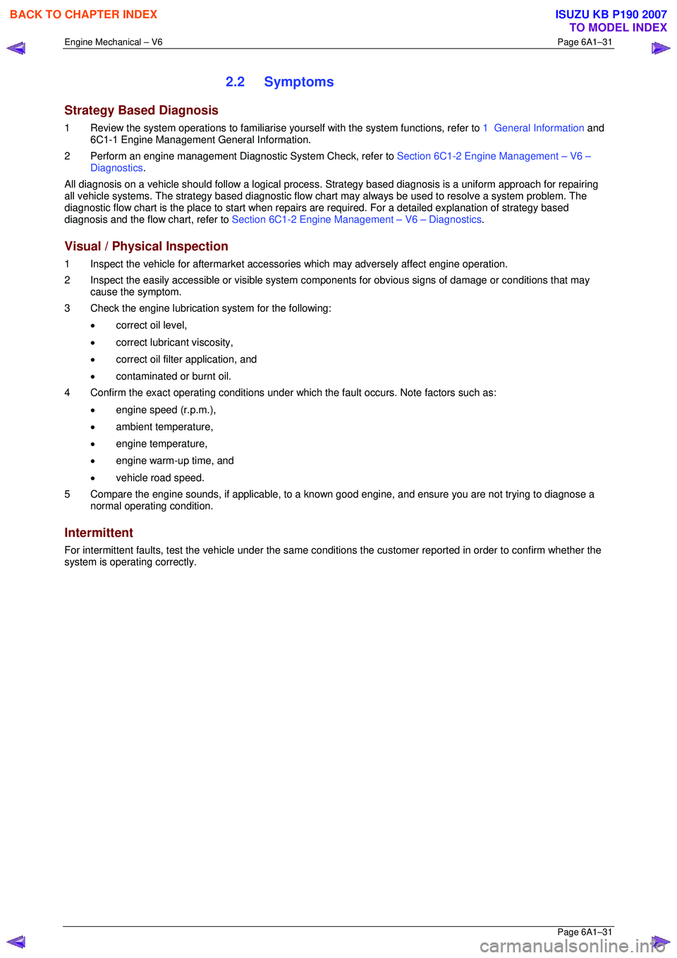
2.2 Symptoms
Strategy Based Diagnosis
1 Review the system operations to familiarise yourself with the system functions, refer to 1 General Information and
6C1-1 Engine Management General Information.
2 Perform an engine management Diagnostic System Check, refer to Section 6C1-2 Engine Management – V6 –
Diagnostics .
All diagnosis on a vehicle should follow a logical process. Strategy based diagnosis is a uniform approach for repairing
all vehicle systems. The strategy based diagnostic flow chart may always be used to resolve a system problem. The
diagnostic flow chart is the place to start when repairs are required. For a detailed explanation of strategy based
diagnosis and the flow chart, refer to Section 6C1-2 Engine Management – V6 – Diagnostics .
Visual / Physical Inspection
1 Inspect the vehicle for aftermarket accessories which may adversely affect engine operation.
2 Inspect the easily accessible or visible system components for obvious signs of damage or conditions that may cause the symptom.
3 Check the engine lubrication system for the following:
• correct oil level,
• correct lubricant viscosity,
• correct oil filter application, and
• contaminated or burnt oil.
4 Confirm the exact operating conditions under whic h the fault occurs. Note factors such as:
• engine speed (r.p.m.),
• ambient temperature,
• engine temperature,
• engine warm-up time, and
• vehicle road speed.
5 Compare the engine sounds, if applic able, to a known good engine, and ensure you are not trying to diagnose a
normal operating condition.
Intermittent
For intermittent faults, test the vehicle under the same conditions the customer reported in order to confirm whether the
system is operating correctly.
BACK TO CHAPTER INDEX
TO MODEL INDEX
ISUZU KB P190 2007
Page 2815 of 6020
Engine Mechanical – V6 Page 6A1–38
Page 6A1–38
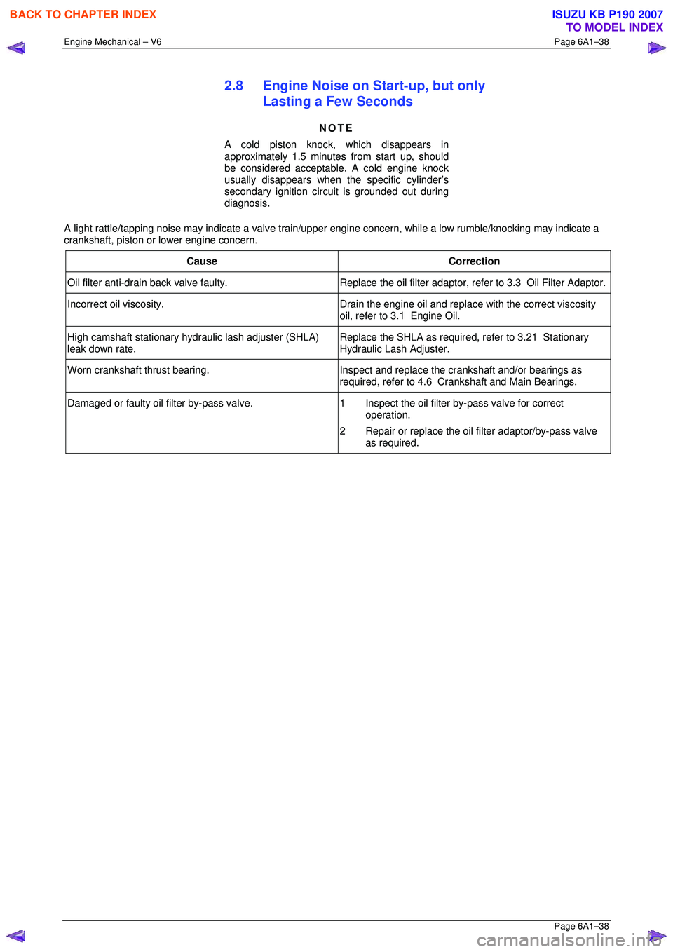
2.8 Engine Noise on Start-up, but only
Lasting a Few Seconds
NOTE
A cold piston knock, which disappears in
approximately 1.5 minutes from start up, should
be considered acceptable. A cold engine knock
usually disappears when t he specific cylinder’s
secondary ignition circuit is grounded out during
diagnosis.
A light rattle/tapping noise may indicate a valve train/upper engine concern, while a low rumble/knocking may indicate a
crankshaft, piston or lower engine concern.
Cause Correction
Oil filter anti-drain back valve faulty. Replace the o il filter adaptor, refer to 3.3 Oil Filter Adaptor.
Incorrect oil viscosity.
Drain the engine oil and replace with the correct viscosity
oil, refer to 3.1 Engine Oil.
High camshaft stationary hydraulic lash adjuster (SHLA)
leak down rate. Replace the SHLA as required,
refer to 3.21 Stationary
Hydraulic Lash Adjuster.
Worn crankshaft thrust bearing. Inspect and replace the crankshaft and/or bearings as
required, refer to 4.6 Crankshaft and Main Bearings.
Damaged or faulty oil filter by-pass valve. 1 Inspect the oil filter by-pass valve for correct
operation.
2 Repair or replace the oil filter adaptor/by-pass valve
as required.
BACK TO CHAPTER INDEX
TO MODEL INDEX
ISUZU KB P190 2007
Page 2824 of 6020
Engine Mechanical – V6 Page 6A1–47
Page 6A1–47
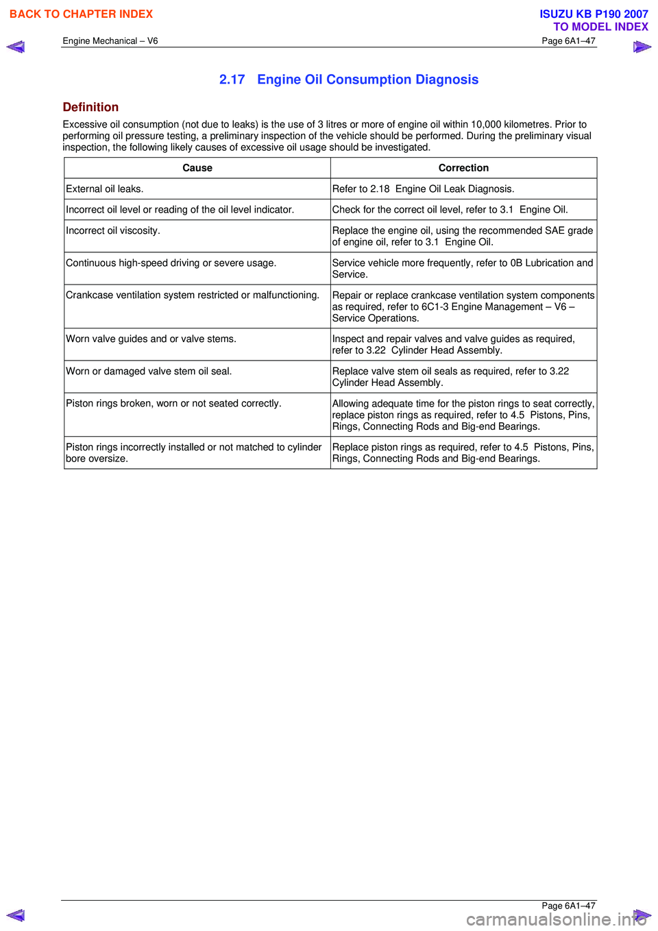
2.17 Engine Oil Consumption Diagnosis
Definition
Excessive oil consumption (not due to leaks) is the use of 3 litres or more of engine oil within 10,000 kilometres. Prior to
performing oil pressure testing, a prelim inary inspection of the vehicle should be performed. During the preliminary visual
inspection, the following likely causes of excessive oil usage should be investigated.
Cause Correction
External oil leaks. Refer to 2.18 Engine Oil Leak Diagnosis.
Incorrect oil level or reading of the oil level indicator. C heck for the correct oil level, refer to 3.1 Engine Oil.
Incorrect oil viscosity.
Replace the engine oil, using the recommended SAE grade
of engine oil, refer to 3.1 Engine Oil.
Continuous high-speed driving or severe usage. Service vehicle more frequently, refer to 0B Lubrication and
Service.
Crankcase ventilation system restricted or malfunctioning. Repair or replace crankcase ventilation system components
as required, refer to 6C1-3 Engine Management – V6 –
Service Operations.
Worn valve guides and or valve stems. Inspect and repair valves and valve guides as required,
refer to 3.22 Cylinder Head Assembly.
Worn or damaged valve stem oil seal. Replace valve stem oil seals as required, refer to 3.22
Cylinder Head Assembly.
Piston rings broken, worn or not seated correctly. Allowing adequate time for the piston rings to seat correctly,
replace piston rings as required, refer to 4.5 Pistons, Pins,
Rings, Connecting Rods and Big-end Bearings.
Piston rings incorrectly installed or not matched to cylinder
bore oversize. Replace piston rings as required, refer to 4.5 Pistons, Pins,
Rings, Connecting Rods and Big-end Bearings.
BACK TO CHAPTER INDEX
TO MODEL INDEX
ISUZU KB P190 2007