2007 ISUZU KB P190 jump cable
[x] Cancel search: jump cablePage 2142 of 6020
ENGINE ELECTRICAL 6D1-5
Battery fluid is a highly corrosive acid.
Should battery fluid come in contact with your eyes, skin,
fabric, or a painted surface, immediately and thoroughly rinse
the affected area with clean tap water.
Never allow metal tools or jumper cables to come in contact
with the positive battery terminal, or any other metal surface of
the vahicle. This will protect against a short circuit.
Always keep batteries out of reach of young children.
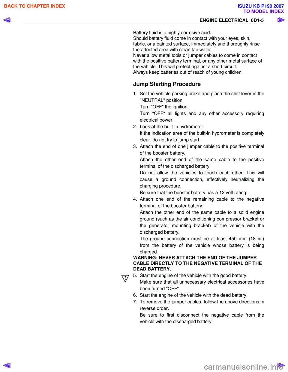
Jump Starting Procedure
1. Set the vehicle parking brake and place the shift lever in the
"NEUTRAL" position.
Turn "OFF" the ignition.
Turn "OFF" all lights and any other accessory requiring electrical power.
2. Look at the built-in hydrometer.
If the indication area of the built-in hydrometer is completel
y
clear, do not try to jump start.
3.
Attach the end of one jumper cable to the positive terminal
of the booster battery.
Attach the other end of the same cable to the positive
terminal of the discharged battery.
Do not allow the vehicles to touch each other. This will cause a ground connection, effectively neutralizing the
charging procedure.
Be sure that the booster battery has a 12 volt rating.
4.
Attach one end of the remaining cable to the negative
terminal of the booster battery.
Attach the other end of the same cable to a solid engine ground (such as the air conditioning compressor bracket o
r
the generator mounting bracket) of the vehicle with the
discharged battery.
The ground connection must be at least 450 mm (18 in.) from the battery of the vehicle whose battery is being
charged.
WARNING: NEVER ATTACH THE END OF THE JUMPER
CABLE DIRECTLY TO THE NEGATIVE TERMINAL OF THE
DEAD BATTERY.
5. Start the engine of the vehicle with the good battery.
Make sure that all unnecessary electrical accessories have been turned "OFF".
6. Start the engine of the vehicle with the dead battery.
7. To remove the jumper cables, follow the above directions in reverse order.
Be sure to first disconnect the negative cable from the vehicle with the discharged battery.
BACK TO CHAPTER INDEX
TO MODEL INDEX
ISUZU KB P190 2007
Page 2279 of 6020
ENGINE DRIVEABILITY AND EMISSIONS 6E–109
• The fuel injector(s).
4. Fuel pressure that drops off during acceleration, cruise, or hard cornering may case a lean condition.
A lean condition can cause a loss of power, surging,
or misfire. A lean condition can be diagnosed using a
Tech 2 Scan Tool.
Following are applicable to the vehicle with
closed Loop System:
If an extremely lean condition occurs, the oxygen
sensor(s) will stop toggling. The oxygen sensor
output voltage(s) will drop below 500 mV. Also, the
fuel injector pulse width will increase.
Important: Make sure the fuel system is not
operating in the “Fuel Cut-Off Mode.”
When the engine is at idle, the manifold pressure is
low (high vacuum). This low pressure (high vacuum)
is applied to the fuel pressure regulator diaphragm.
The low pressure (high vacuum) will offset the
pressure being applied to the fuel pressure regulator
diaphragm by the spring inside the fuel pressure
regulator. When this happens, the result is lower fuel
pressure. The fuel pressure at idle will vary slightly
as the barometric pressure changes, but the fuel
pressure at idle should always be less than the fuel
pressure noted in step 2 with the engine OFF.
16.Check the spark plug associated with a particular
fuel injector for fouling or saturation in order to
determine if that particular fuel injector is leaking. If
checking the spark plug associated with a particular
fuel injector for fouling or saturation does not
determine that a particular fuel injector is leaking,
use the following procedure:
• Remove the fuel rail, but leave the fuel lines and injectors connected to the fuel rail. Refer to Fuel
Rail Assembly in On-Vehicle Service .
• Lift the fuel rail just enough to leave the fuel injector nozzles in the fuel injector ports.
Caution: In order to reduce the risk of fire and
personal injury that may result from fuel
spraying on the engine, verify that the fuel rail is
positioned over the fuel injector ports and verify
that the fuel injector retaining clips are intact.
• Pressurize the fuel system by connecting a 20 amp fused jumper between B+ and the fuel
pump relay connector.
• Visually and physically inspect the fuel injector nozzles for leaks.
17.A rich condition may result from the fuel pressure being above 376 kPa (55 psi). A rich condition may
cause a 45 to set. Driveability conditions associated with rich conditions can include hard starting
(followed by black smoke) and a strong sulfur smell
in the exhaust.
20.This test determines if the high fuel pressure is due to a restricted fuel return line or if the high fuel
pressure is due to a faulty fuel pressure regulator.
21.A lean condition may result from fuel pressure below 333 kPa (48 psi). A lean condition may cause a 44 to
set. Driveability conditions associated with lean
conditions can include hard starting (when the
engine is cold), hesitation, poor driveability, lack of
power, surging, and misfiring.
22.Restricting the fuel return line causes the fuel pressure to rise above the regulated fuel pressure.
Command the fuel pump ON with the scan tool. The
fuel pressure should rise above 376 kPa (55 psi) as
the fuel return line becomes partially closed.
NOTE: Do not allow the fuel pressure to exceed 414
kPa (60 psi). Fuel pressure in excess of 414 kPa (60
psi) may damage the fuel pressure regulator. Caution: To reduce the risk of fire and personal
injury:
• It is necessary to relieve fuel system pressure before connecting a fuel pressure gauge.
Refer to Fuel Pressure Relief Procedure,
below.
• A small amount of fuel may be released when disconnecting the fuel lines. Cover fuel line
fittings with a shop towel before
disconnecting, to catch any fuel that may leak
out. Place the towel in an approved container
when the disconnect is completed.
Fuel Pressure Relief Procedure
1. Remove the fuel cap.
2. Located on the intake manifold which is at the top right part of the engine.
3. Start the engine and allow it to stall.
4. Crank the engine for an additional 3 seconds.
Fuel Pressure Gauge Installation
1. Remove the fuel pressure fitting cap.
2. Install fuel pressure gauge 5-8840-0378-0 to the fuel feed line located on the upper right side of the
engine.
3. Reinstall the fuel pump relay.
BACK TO CHAPTER INDEX
TO MODEL INDEX
ISUZU KB P190 2007
Page 2287 of 6020
ENGINE DRIVEABILITY AND EMISSIONS 6E–11 7
P0351 A Ignition 1 Control Circuit #1 or #4cylinder ignition signals are not
detected consecutively. No fail-safe function.
Consecutive ignition signals are detected. 1. Ignition coil module 1 harness open
circuit, short to ground or short to voltage
circuit.
2. Ignition coil module malfunction.
3. ECM malfunction. J1-19
P0352 A Ignition 2 Control Circuit #2 or #3 cylinder ignition signals are not
detected consecutively. 1. Ignition coil module 2 harness open circuit,
short to ground or short to voltage circuit.
2. Ignition coil module malfunction.
3. ECM malfunction. J1-18
P0443 B EVAP Emission Control System Purge Control Circuit EVAP purge solenoid circuit open, short to
ground or short to voltage circuit. No fail-safe function.
EVAP purge solenoid circuit is correct
condition. 1. Solenoid harness open circuit, short to
ground or short to voltage circuit.
2. Solenoid malfunction.
3. ECM malfunction. J1-5
P0502 B Vehicle Speed Sensor Circuit Low Input 1. No DTC relating to MAP sensor, TPS, ECT sensor, injector control circuit and
ignition control circuit.
2. Engine is running.
3. Vehicle speed is below 3km/h in power condition or 2km/h in deceleration
condition. ECM uses 0km/h condition as
substitute. VSS circuit correct condition.
1. Sensor harness open circuit, short to
ground circuit or short to voltage circuit.
2. Poor connector connection.
3. VSS malfunction.
4. ECM malfunction. J2-23
P0562 D System Voltage Low Battery voltage is below 11V.No fail-safe function.Battery voltage is between 11V and 16V. 1. Battery power feed harness open circuit
or short to ground circuit.
2. ECM ground harness open or poor connection.
3. Poor connector connection.
4. Battery malfunction.
5. Charge system malfunction.
6. ECM malfunction. -
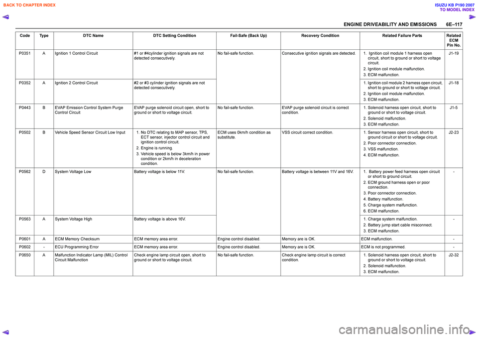
P0563 A System Voltage High Battery voltage is above 16V. 1. Charge system malfunction.
2. Battery jump start cable misconnect.
3. ECM malfunction. -
P0601 A ECM Memory Checksum ECM memory area error.Engine control disabled.Memory are is OK. ECM malfunction. -
P0602 - ECU Programming Error ECM memory area error.Engine control disabled.Memory are is OK. ECM is not programmed. -
P0650 A Malfunction Indicator Lamp (MIL) Control Circuit Malfunction Check engine lamp circuit open, short to
ground or short to voltage circuit. No fail-safe function.
Check engine lamp circuit is correct
condition. 1. Solenoid harness open circuit, short to
ground or short to voltage circuit.
2. Solenoid malfunction.
3. ECM malfunction. J2-32
Code Type
DTC Name DTC Setting Condition Fail-Safe (Back Up)Recovery Condition Related Failure PartsRelated
ECM
Pin No.
BACK TO CHAPTER INDEX
TO MODEL INDEX
ISUZU KB P190 2007
Page 3597 of 6020
Charging System – V6 Page 6D1-1-10
3 Minor Service Operations
3.1 Safety Precautions
Observe the following precautions. Failure to observe these precautions will result in serious damage to the generator.
• Only use the generator and voltage regulator in a negative ground system.
• Always refer to 1.2 W ARNING, CAUTION and NOTES before disconnecting the battery.
• W hen installing a battery, fit the positive (+) cable to the battery before fitting the negative cable.
• W hen a slave battery is used for starting purposes, ensure that both batteries are connected in parallel. That is,
positive terminals connected and negative terminals connected.
• Only use jumper leads that have surge protection.
• Disconnect both battery cables when charging the battery. This isolates the generator from the battery and from
the external charging equipment.
• Do not operate the generator within an open circuit or without a battery in the circuit.
• Do not disconnect the battery while the generator is running.
• Do not attempt to polarise the generator.
• Do not connect generator connector E-4 pin 1 to 12 V (the battery or ignition circuits).
• Some battery powered timing lights can produce high transient voltages when connected or disconnected.
Only disconnect or connect timing lights when the engine is switched off.
Ensure the generator connector E-4 pin 1 has
a maximum sinking current of 50mA.
3.2 Maintenance
Regular Checks
Check the following at regular intervals:
• generator terminals – for corrosion and loose connections,
• wiring – for continuity and damaged insulation,
• mounting bolts – for tightness,
• drive belt – for alignment and wear, and
• drive pulley – for damage and warping.
NOTE
The drive-belt adjustment for the engine
ancillaries (i.e. generator and water pump) is
provided by a spring-loaded tensioner. Therefore,
the drive belt does not require manual
adjustment.
Lubrication
High tolerance bearings are used in this generator. If the bearings are removed during the generator disassembly, new
bearings must be installed to restore the generator to original specification. The ball bearings supporting the rotor shaft
are pre-lubricated and sealed. Do not attempt to lubricate these during servicing.
BACK TO CHAPTER INDEX
TO MODEL INDEX
ISUZU KB P190 2007
Page 3623 of 6020
Starting System – V6 Page 6D1-2–15
3 Minor Service Operations
3.1 Safety Precautions
Observe the following precautions. Failure to observe these precautions can result in serious damage to components.
• Refer to 1.1 W ARNING, CAUTION and NOTES in this Service Information before disconnecting the battery.
• Use the starter motor on a negative ground system only.
• W hen installing a battery, attach the positive (+) cable to the battery first. Then attach the negative cable.
• W hen using a slave battery for starting purposes, ensure that both batteries are connected in parallel, that is.
positive to positive terminals and negative to negative terminals.
• Only use jumper leads that have surge protection.
3.2 Maintenance
Regular Checks
Check the following at regular intervals:
• Starter motor terminals – for corrosion and loose connectors.
• W iring – for damaged insulation.
• Mounting bolts – for tightness.
• Battery terminals – for clean and secure connections.
3.3 On-Vehicle Testing
NOTE
The battery must be fully charged and in
serviceable condition before beginning these
tests, refer to 8A Electrical Body and Chassis.
BACK TO CHAPTER INDEX
TO MODEL INDEX
ISUZU KB P190 2007
Page 3641 of 6020
Battery Page 6D1-3–1
6D1-3
Battery – V6
ATTENTION
Before performing any service operation or other procedure described in this Section, refer to 1.1
WARNING, CAUTION and NOTES for correct workshop practices with regard to safety and/or property
damage.
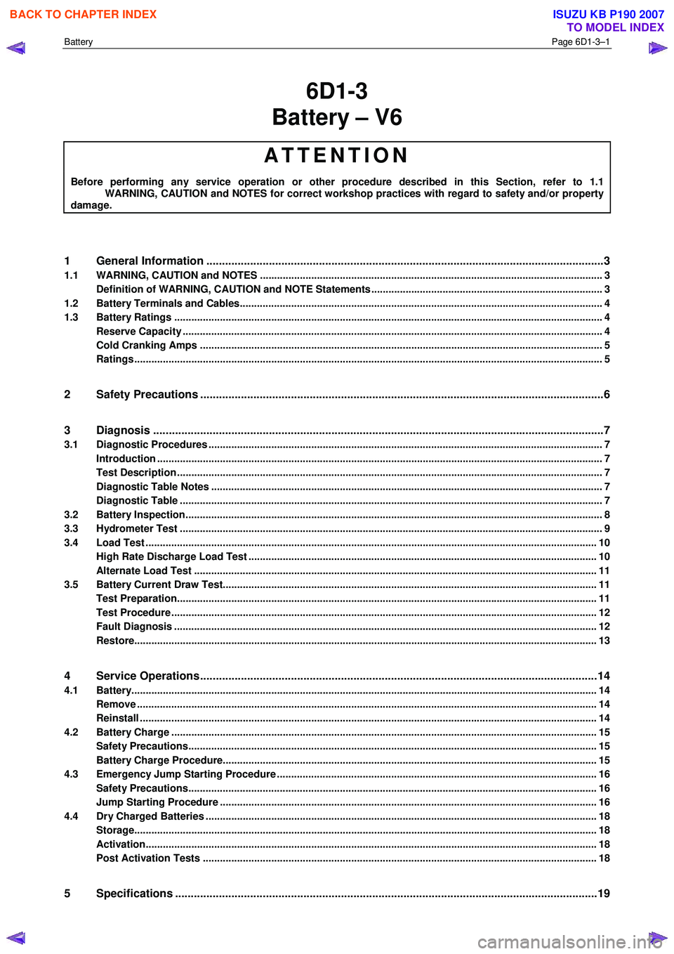
1 General Information ............................................................................................................ ...................3
1.1 WARNING, CAUTION and NOTES ..................................................................................................... ................... 3
Definition of WARNING, CAUTION and NOTE Statements ............................................................................. .... 3
1.2 Battery Terminals and Cables............................................................................................................................... 4
1.3 Battery Ratings ...................................................................................................................................................... 4
Reserve Capacity ............................................................................................................... .................................... 4
Cold Cranking Amps ............................................................................................................................................. 5
Ratings.................................................................................................................................................................... 5
2 Safety Precautions .................................................................................................................................6
3 Diagnosis ................................................................................................................................................7
3.1 Diagnostic Procedures .......................................................................................................................................... 7
Introduction ............................................................................................................................................................ 7
Test Description ..................................................................................................................................................... 7
Diagnostic Table Notes ......................................................................................................................................... 7
Diagnostic Table .................................................................................................................................................... 7
3.2 Battery Inspection.................................................................................................................................................. 8
3.3 Hydrometer Test .................................................................................................................................................... 9
3.4 Load Test ...................................................................................................................... ........................................ 10
High Rate Discharge Load Test .................................................................................................. ........................ 10
Alternate Load Test ............................................................................................................................................. 11
3.5 Battery Current Draw Test...................................................................................................... ............................. 11
Test Preparation................................................................................................................................................... 11
Test Procedure ..................................................................................................................................................... 12
Fault Diagnosis .................................................................................................................................................... 12
Restore.................................................................................................................................................................. 13
4 Service Operations ...............................................................................................................................14
4.1 Battery................................................................................................................................................................... 14
Remove ......................................................................................................................... ........................................ 14
Reinstall ................................................................................................................................................................ 14
4.2 Battery Charge ................................................................................................................. .................................... 15
Safety Precautions............................................................................................................. .................................. 15
Battery Charge Procedure....................................................................................................... ............................ 15
4.3 Emergency Jump Starting Procedure .............................................................................................. .................. 16
Safety Precautions............................................................................................................................................... 16
Jump Starting Procedure ........................................................................................................ ............................ 16
4.4 Dry Charged Batteries ......................................................................................................................................... 18
Storage.................................................................................................................................................................. 18
Activation..................................................................................................................... ......................................... 18
Post Activation Tests .......................................................................................................... ................................ 18
5 Specifications .......................................................................................................................................19
BACK TO CHAPTER INDEX
TO MODEL INDEX
ISUZU KB P190 2007
Page 3646 of 6020
Battery Page 6D1-3–6
2 Safety Precautions
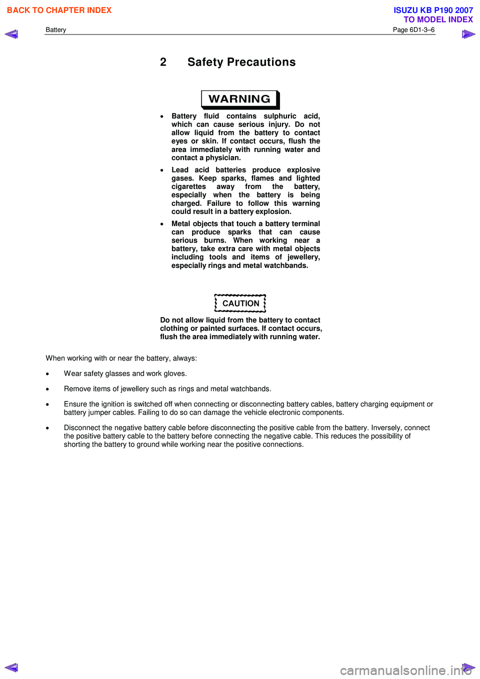
• Battery fluid contains sulphuric acid,
which can cause serious injury. Do not
allow liquid from the battery to contact
eyes or skin. If contact occurs, flush the
area immediately with running water and
contact a physician.
• Lead acid batteries produce explosive
gases. Keep sparks, flames and lighted
cigarettes away from the battery,
especially when the battery is being
charged. Failure to follow this warning
could result in a battery explosion.
• Metal objects that touch a battery terminal
can produce sparks that can cause
serious burns. When working near a
battery, take extra care with metal objects
including tools and items of jewellery,
especially rings and metal watchbands.
Do not allow liquid from the battery to contact
clothing or painted surfaces. If contact occurs,
flush the area immediately with running water.
W hen working with or near the battery, always:
• W ear safety glasses and work gloves.
• Remove items of jewellery such as rings and metal watchbands.
• Ensure the ignition is switched off when connecting or disconnecting battery cables, battery charging equipment or
battery jumper cables. Failing to do so can damage the vehicle electronic components.
• Disconnect the negative battery cable before disconnecting the positive cable from the battery. Inversely, connect
the positive battery cable to the battery before connecting the negative cable. This reduces the possibility of
shorting the battery to ground while working near the positive connections.
BACK TO CHAPTER INDEX
TO MODEL INDEX
ISUZU KB P190 2007
Page 3656 of 6020
Battery Page 6D1-3–16
NOTE
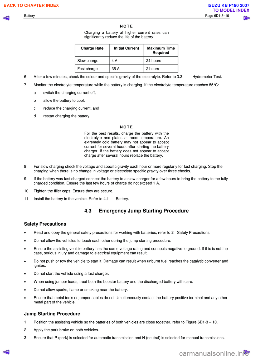
Charging a battery at higher current rates can
significantly reduce the life of the battery.
Charge Rate Initial Current Maximum Time Required
Slow charge 4 A 24 hours
Fast charge 35 A 2 hours
6 After a few minutes, check the colour and specific gravity of the electrolyte. Refer to 3.3 Hydrometer Test.
7 Monitor the electrolyte temperature while the battery is charging. If the electrolyte temperature reaches 55 °C:
a switch the charging current off,
b allow the battery to cool,
c reduce the charging current, and
d restart charging the battery.
NOTE
For the best results, charge the battery with the
electrolyte and plates at room temperature. An
extremely cold battery may not appear to accept
current for several hours after starting the battery
charger. If the battery does not appear to accept
charge after several hours replace the battery.
8 For slow charging check the voltage and specific gravity each hour or more regularly for fast charging. Stop the charging when there is no change in voltage or electrolyte specific gravity over three checks.
9 If the battery was fast charged connect the battery to a slow-charger for a few hours to bring the battery to the fully charged condition. Ensure the last few hours of charge do not exceed 1 A.
10 Tighten the filler caps. Ensure they are secure.
11 Install the battery in the vehicle. Refer to 4.1 Battery.
4.3 Emergency Jump Starting Procedure
Safety Precautions
• Read and obey the general safety precautions for working with batteries, refer to 2 Safety Precautions.
• Do not allow the vehicles to touch each other during the jump starting procedure.
• Ensure the assisting vehicle battery has the same voltage rating and connects negative to ground. If this is not the
case, serious injury and damage to electrical equipment can result.
• Do not push or tow the vehicle to start it. Damage can result when unburnt fuel reaches the catalytic converter and
ignites.
• Do not start the vehicle using a fast charger.
• W hen using jumper leads, treat both the booster battery and the discharged battery with care.
• Do not allow sparks, flame or smoking near the battery.
• Ensure that metal tools or jumper cables do not simultaneously contact the battery positive terminal and any other
metal part of the vehicle.
Jump Starting Procedure
1 Position the assisting vehicle so the batteries of both vehicles are close together, refer to Figure 6D1-3 – 10.
2 Apply the park brake on both vehicles.
3 Ensure that P (park) is selected for automatic transmission and N (neutral) is selected for manual transmissions.
BACK TO CHAPTER INDEX
TO MODEL INDEX
ISUZU KB P190 2007