2007 ISUZU KB P190 jump cable
[x] Cancel search: jump cablePage 3657 of 6020

Battery Page 6D1-3–17
4 Turn off the ignition, lights and all other electrical loads.
5 Check the battery filler caps on both batteries are tight.
6 Place a wet cloth over the battery filler caps of each battery.
7 Attach one end of the red jumper cable to the positive terminal of the booster battery.
8 Attach the other end of the same cable to the positive terminal of the discharged battery.
9 Attach one end of the black jumper cable to the negative terminal of the booster battery.
10 Attach the other end to a solid stationary, metallic point on the engine of the disabled vehicle.
NOTE
Do not connect this end directly to the negative
post of the discharged battery.
Figure 6D1-3 – 10
Legend
Order of hook-up:
1 Booster vehicle, positive terminal
2 Disabled vehicle, positive terminal
3 Booster vehicle, negative terminal
4 Disabled vehicle, engine ground point Booster vehicle
Disabled vehicle
11 Ensure the jumper cables are not on or near drive pulleys, cooling fans or other points that will move when the engine is started.
12 Start the engine in the booster vehicle and run the engine at a moderate speed for a few minutes.
13 Start the engine in the disabled vehicle.
NOTE
If the engine in the disabled vehicle does not start
within 30 seconds, stop cranking the engine and
fix the cause. Refer to 3 Diagnosis.
14 W hen the engine starts, allow both engines to idle for approximately seven minutes. This allows the voltage levels in both vehicles to balance.
15 Leave the vehicles running and remove the jumper cables in the reverse sequence to attaching them. W hen removing each clamp, take care to ensure that it does not touch any other metal.
16 Discard the wet cloths covering the battery filler caps of both batteries.
BACK TO CHAPTER INDEX
TO MODEL INDEX
ISUZU KB P190 2007
Page 4334 of 6020

7A2-50 TRANSMISSION CONTROL SYSTEM (JR405E)
DTC P0727 (Flash Code 13)
Circuit Description
The engine speed signal to the TCM is sent from the
engine control module (ECM) via a signal circuit based
on inputs from the crankshaft position (CKP) sensor
and camshaft position (CMP) sensor. If the TCM
detects no engine speed signal from the ECM during
the vehicle running, this DTC will set.
Condition for Running the DTC • The ignition switch is ON.
• The vehicle speed is more than 40 km/h (24 MPH).
Condition for Setting the DTC • The TCM detects that the engine speed signal pulses from the ECM are not being received for 2
seconds. Action Taken When the DTC Sets
• The TCM blinks the Check Trans lamp when the diagnostic runs and fails.
• The TCM inhibits lock up control.
Condition for Clearing the DTC • The TCM turns OFF the Check Trans lamp when the diagnostic runs and does not fail.
• A current DTC clears when the diagnostic runs and does not fail.
Diagnostic Aids • If an intermittent condition is suspected, refer to Intermittent Conditions in this section.
Schematic Reference: Transmission Controls
Schematics
Connector End View Reference: Transmission
Controls Connector End Views or TCM Connector End
Views
Circuit/ System Testing DTC P0727
Step Action Value(s)Yes No
1 Did you perform the Diagnostic System Check -
Transmission Controls? —
Go to Step 2 Go to Diagnostic
System Check -
Transmission Controls
2 1. Install a scan tool.
2. Turn OFF the ignition for 30 seconds.
3. Start the engine. If the engine does not start, crank over the engine for 10 seconds.
4. Monitor the ENGINE DTC Information with a scan tool.
Is DTC P0335, P0336, P0340 or P0341 set? —
Go to Applicable DTC in engine
control section Go to Step 3
3 Observe the Engine Speed parameter in the
transmission data display with a scan tool.
Does the scan tool indicate correct engine speed? —
Go to Diagnostic
Aids Go to Step 4
4 1. Turn OFF the ignition.
2. Disconnect the engine control module (ECM) harness connector.
3. Turn ON the ignition, with the engine OFF.
4. Intermittently jump the signal circuit (pin 33 of C-58) with a test lamp that is connected to a
known good ground while observing the
Engine Speed parameter with a scan tool.
Does the scan tool indicate any engine speed when
the circuit is intermittently pulled to ground? —
Go to Step 7 Go to Step 5
BACK TO CHAPTER INDEX
TO MODEL INDEX
ISUZU KB P190 2007
Page 4957 of 6020

ELECTRICAL-BODY AND CHASSIS 8A-19
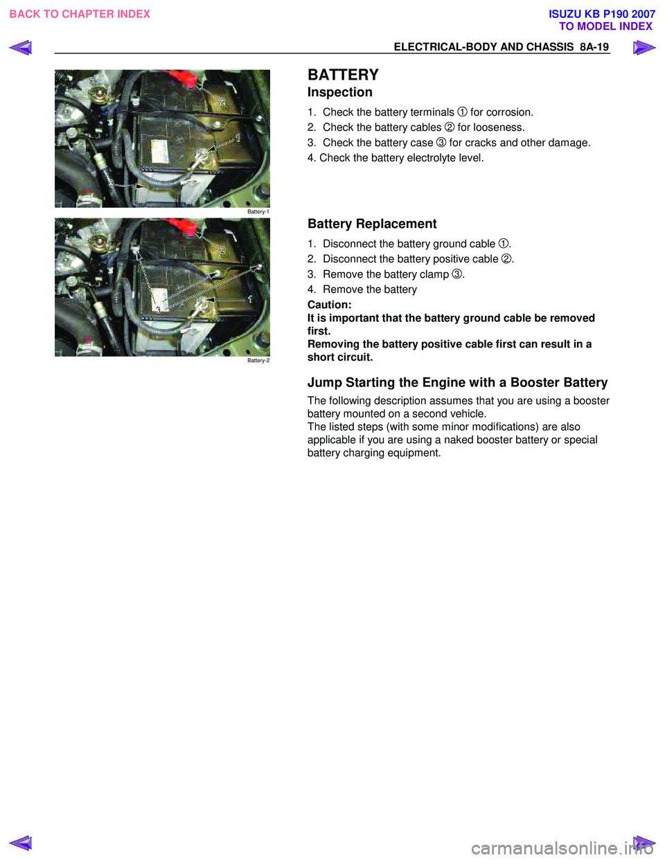
Battery-1
BATTERY
Inspection
1. Check the battery terminals 1 for corrosion.
2. Check the battery cables
2 for looseness.
3. Check the battery case
3 for cracks and other damage.
4. Check the battery electrolyte level.
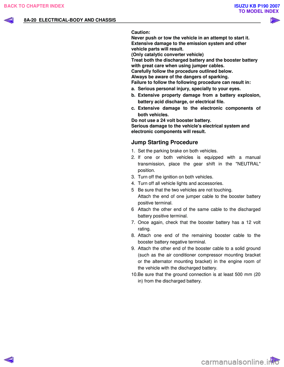
Battery-2
Battery Replacement
1. Disconnect the battery ground cable 1.
2. Disconnect the battery positive cable
2.
3. Remove the battery clamp
3.
4. Remove the battery
Caution:
It is important that the battery ground cable be removed
first.
Removing the battery positive cable first can result in a
short circuit.
Jump Starting the Engine with a Booster Battery
The following description assumes that you are using a booster
battery mounted on a second vehicle.
The listed steps (with some minor modifications) are also
applicable if you are using a naked booster battery or special
battery charging equipment.
BACK TO CHAPTER INDEX TO MODEL INDEXISUZU KB P190 2007
Page 4958 of 6020

8A-20 ELECTRICAL-BODY AND CHASSIS
Caution:
Never push or tow the vehicle in an attempt to start it.
Extensive damage to the emission system and other
vehicle parts will result.
(Only catalytic converter vehicle)
Treat both the discharged battery and the booster battery
with great care when using jumper cables.
Carefully follow the procedure outlined below.
Always be aware of the dangers of sparking.
Failure to follow the following procedure can result in:
a. Serious personal injury, specially to your eyes.
b. Extensive property damage from a battery explosion, battery acid discharge, or electrical file.
c. Extensive damage to the electronic components o
f
both vehicles.
Do not use a 24 volt booster battery.
Serious damage to the vehicle's electrical system and
electronic components will result.
Jump Starting Procedure
1. Set the parking brake on both vehicles.
2. If one or both vehicles is equipped with a manual transmission, place the gear shift in the "NEUTRAL"
position.
3. Turn off the ignition on both vehicles.
4. Turn off all vehicle lights and accessories.
5 Be sure that the two vehicles are not touching.
Attach the end of one jumper cable to the booster battery
positive terminal.
6
Attach the other end of the same cable to the discharged
battery positive terminal.
7. Once again, check that the booster battery has a 12 volt rating.
8.
Attach one end of the remaining booster cable to the
booster battery negative terminal.
9.
Attach the other end of the booster cable to a solid ground
(such as the air conditioner compressor mounting bracket
or the alternator mounting bracket) in the engine room o
f
the vehicle with the discharged battery.
10.Be sure that the ground connection is at least 500 mm (20 in) from the discharged battery.
BACK TO CHAPTER INDEX TO MODEL INDEXISUZU KB P190 2007
Page 4959 of 6020

ELECTRICAL-BODY AND CHASSIS 8A-21
Caution:
Do not attach the booster cable to the discharged battery
negative terminal.
11. Start the engine of the vehicle with the booster battery.
Check that all unnecessary electrical accessories are off.
12. Start the engine of the vehicle with the discharged battery.
13. Remove the jumper cables in the reverse order to which they were attached.
Caution:
Be absolutely sure to remove the negative jumper cable
from the vehicle with the discharged battery first.
BACK TO CHAPTER INDEX TO MODEL INDEXISUZU KB P190 2007
Page 5759 of 6020

CAB 10-1
SECTION 10
CAB
TABLE OF CONTENTS
PAGE
Windshield ..................................................................................................................... .... 10- 2
Rear Window Assembly .................................................................................................... 10- 6
Front Door Assembly ........................................................................................................ 10- 9
Rear Door Assembly (Crew Cab) ..................................................................................... 10- 19
Instrument Panel ............................................................................................................... 10- 27
Floor Console .................................................................................................................. .. 10- 35
Console Box (Without Floor Console) ............................................................................. 10- 39
Headlining ..................................................................................................................... ..... 10- 40
Interior Trim Panels ........................................................................................................... 10- 45
Fuel Filler Lid Opener Lever/Cable .................................................................................. 10- 56
Quarter Glass (Extend Cab).............................................................................................. 10- 71
Font Seat ...................................................................................................................... ...... 10- 72
Rear Seat (Crew Cab) ........................................................................................................ 10- 74
Jump Seat (Extend Cab) ................................................................................................... 10- 75
Front Seat Belt ................................................................................................................ ... 10- 76
Rear Seat Belt (Crew Cab) ................................................................................................ 10- 80
Rear Seat Belt (Extend Cab) ............................................................................................. 10- 84
Front Wheel Extension (A type) ....................................................................................... 10- 87
Front Wheel Extension (B type) ....................................................................................... 10- 88
Rear Wheel Extension (A type)......................................................................................... 10- 89
Rear Wheel Extension (B type)......................................................................................... 10- 90
Tail Gate Assembly ........................................................................................................... 10 - 91
TO MODEL INDEX
BACK TO MAIN INDEX
ISUZU KB P190 2007