2007 ISUZU KB P190 suspension
[x] Cancel search: suspensionPage 2667 of 6020
Engine Mechanical – V6 Page 6A1–188
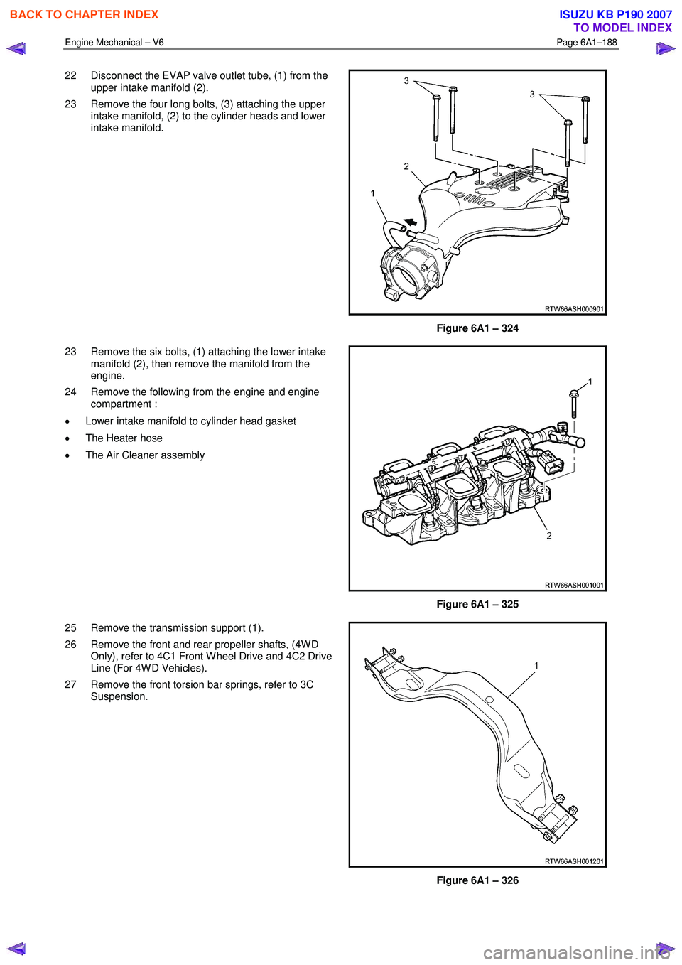
22 Disconnect the EVAP valve outlet tube, (1) from the
upper intake manifold (2).
23 Remove the four long bolts, (3) attaching the upper intake manifold, (2) to the cylinder heads and lower
intake manifold.
Figure 6A1 – 324
23 Remove the six bolts, (1) attaching the lower intake manifold (2), then remove the manifold from the
engine.
24 Remove the following from the engine and engine compartment :
• Lower intake manifold to cylinder head gasket
• The Heater hose
• The Air Cleaner assembly
Figure 6A1 – 325
25 Remove the transmission support (1).
26 Remove the front and rear propeller shafts, (4W D Only), refer to 4C1 Front W heel Drive and 4C2 Drive
Line (For 4W D Vehicles).
27 Remove the front torsion bar springs, refer to 3C Suspension.
Figure 6A1 – 326
BACK TO CHAPTER INDEX
TO MODEL INDEX
ISUZU KB P190 2007
Page 2830 of 6020
Engine Mechanical – V6 Page 6A1–53
Page 6A1–53
Drive Belt Chirp
Definition
Accessory drive belt chirping can be defined as a high-pitched noise that is heard once per revolution of the drive belt or
a pulley.
NOTE
Chirping during start-up in cold damp conditions
that abates once the engine reaches operating
temperature is considered normal.
Diagnostic Aids
The symptom may be intermittent due to moisture on the driv e belts or pulleys. It may be necessary to spray a small
amount of water on the drive belt to dup licate and confirm a customers concern. If spraying water onto the drive belt
system duplicates the symptom, cleaning the belt pulleys may be the solution.
A loose or incorrectly installed body component, suspension component or other item may be the cause of the noise.
Test Description
The numbers below refer to steps in the diagnostic table.
2 The noise may not be engine related. This step is to confirm the engine is making t he noise. If the engine is not
making the noise, do not proceed further with this diagnostic procedure.
3 The noise may be an internal engine noise. Removing the drive belt and operating the engine briefly will confirm
whether or not the noise is related to the drive belt.
CAUTION
When running the engine with the accessory
drive belt removed, the coolant pump will not
be operating and the engine may overheat if
left unsupervised even for a short period.
NOTE
There may also be a number of DTCs set when
running the engine with the accessory drive belt
removed.
4 Inspect all drive pump pulleys for pilling. NOTE
Pilling is the small balls (p ills) or strings of rubber
in the belt grooves caused by the accumulation of
rubber dust.
6 Misalignment of the accessory drive system pulleys ma y be caused by incorrect mounting of an accessory drive
component (A/C compressor, generator etc.) or pulley. Misa lignment may also be caused by incorrect installation of
a pulley during a previous repair. Test for a misaligned pulley using a straight edge in the pulley grooves across
two or three pulleys. If a misaligned pulley is found, refer to the relevant component service information for the
correct installation and removal procedures.
10 Inspecting the fasteners can elim inate the possibility that an incorrect fastener has been installed.
12 Inspecting the pulleys for being bent should include inspec ting for a dent or other damage that would prevent the
drive belt from not seating correctly in all of the pulley grooves or on the smooth surface when the back end of the
belt is used as the driving surface.
14 Replacing the drive belt when it is not damaged and there is no excessive p illing will only be a temporary repair.
BACK TO CHAPTER INDEX
TO MODEL INDEX
ISUZU KB P190 2007
Page 2832 of 6020
Engine Mechanical – V6 Page 6A1–55
Page 6A1–55
Drive Belt Squeal
Definition
Accessory drive belt squealing can be defined as a loud screeching noise caused by a slipping drive belt. Belt squeal is
unusual in multi-rib belts. Drive belt squeal generally occurs when a heavy load is applied to the drive belt, such as an
air-conditioning compressor engagement, snapping the throttle, se ized pulley or a faulty accessory drive component.
Diagnostic Aids
If the noise is intermittent, confirm the accessory drive components by varying t heir loads, making sure they are operated
to their maximum capacity. An overcharged A/C system, restrictions in the power steering pressure circuit or a faulty
generator or coolant pump are likely c auses of accessory drive belt squeal.
A loose or incorrectly installed body component, suspension component or other item may be the cause of the noise.
Test Description
The numbers below refer to steps in the diagnostic table.
2 The noise may not be engine related. This step is to confirm the engine is making t he noise. If the engine is not
making the noise, do not proceed further with this diagnostic procedure.
3 The noise may be an internal engine noise. Removing the drive belt and operating the engine briefly will confirm
whether or not the noise is related to the drive belt.
CAUTION
When running the engine with the accessory
drive belt removed, the coolant pump will not
be operating and the engine may overheat if
left unsupervised even for a short period.
NOTE
There may also be a number of DTCs set when
running the engine with the accessory drive belt
removed.
4 Confirms an accessory drive component does not have a se ized bearing. With the belt removed, test the bearings
in the accessory drive co mponents spin free and smooth.
5 Confirms the drive belt tensioner is operating correctly. If the drive belt tensioner is not operating correctly, drive
belt tension will not be maintained, resulting in a belt squealing noise
6 Confirms the belt is not too long, which would prevent the tensioner from working as intended. Also, if an
excessively long belt has been fitted, it may also be r outed incorrectly and may be turning an accessory drive
component in the wrong direction.
7 Misalignment of the pulleys may be caused by one of the following:
• Incorrect mounting of an accessory drive component,
• Incorrect installation of an accessory drive pulley or,
• Bent or damaged pulley.
Test for a misaligned pulley using a straight edge in the pulley grooves across 2 or 3 pulleys. If a misaligned pulley is found, refer to the relevant component service info rmation for the correct installation and removal procedures.
8 This test is to confirm the pulleys are the correct di ameter and/or width. Using a known good vehicle, compare the
pulley sizes.
Diagnostic Table
Step Action Yes No
1
Did you review the information provided in 2.2 Symptoms, and
perform the required inspections. Go to Step 2 Go to
2.2 Symptoms
2 Confirm the customer compla int. Is there a squealing noise?
Go to Step 3 Refer to Diagnostic
Aids in this Section
BACK TO CHAPTER INDEX
TO MODEL INDEX
ISUZU KB P190 2007
Page 3020 of 6020
Engine Mechanical – V6 Page 6A1–243
Page 6A1–243
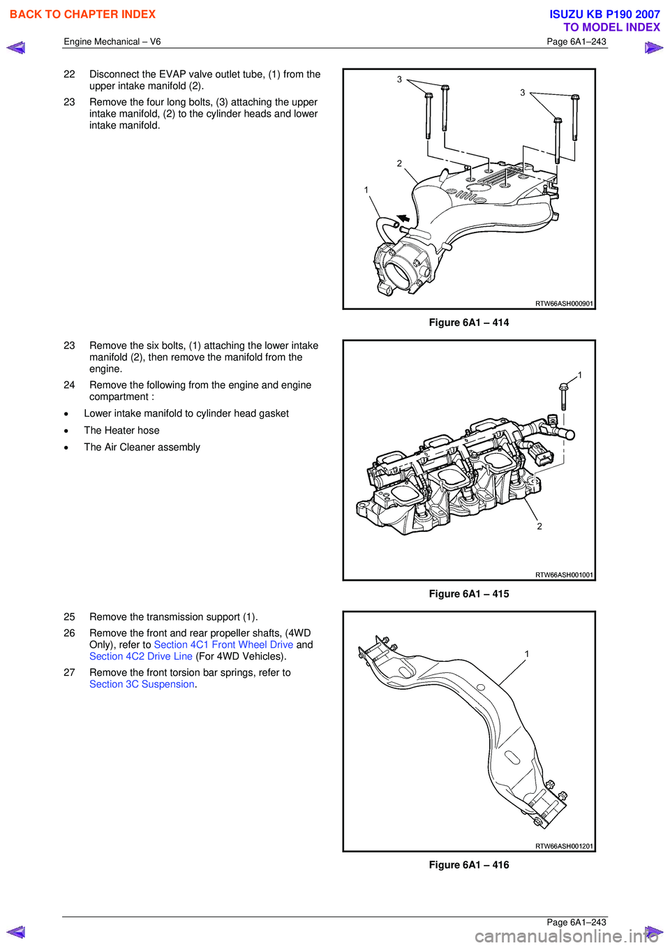
22 Disconnect the EVAP valve outlet tube, (1) from the
upper intake manifold (2).
23 Remove the four long bolts, (3) attaching the upper intake manifold, (2) to the cylinder heads and lower
intake manifold.
Figure 6A1 – 414
23 Remove the six bolts, (1) attaching the lower intake manifold (2), then remove the manifold from the
engine.
24 Remove the following from the engine and engine compartment :
• Lower intake manifold to cylinder head gasket
• The Heater hose
• The Air Cleaner assembly
Figure 6A1 – 415
25 Remove the transmission support (1).
26 Remove the front and rear propeller shafts, (4WD Only), refer to Section 4C1 Front Wheel Drive and
Section 4C2 Drive Line (For 4WD Vehicles).
27 Remove the front torsion bar springs, refer to Section 3C Suspension .
Figure 6A1 – 416
BACK TO CHAPTER INDEX
TO MODEL INDEX
ISUZU KB P190 2007
Page 3755 of 6020
Exhaust System – V6 Page 6F – 7
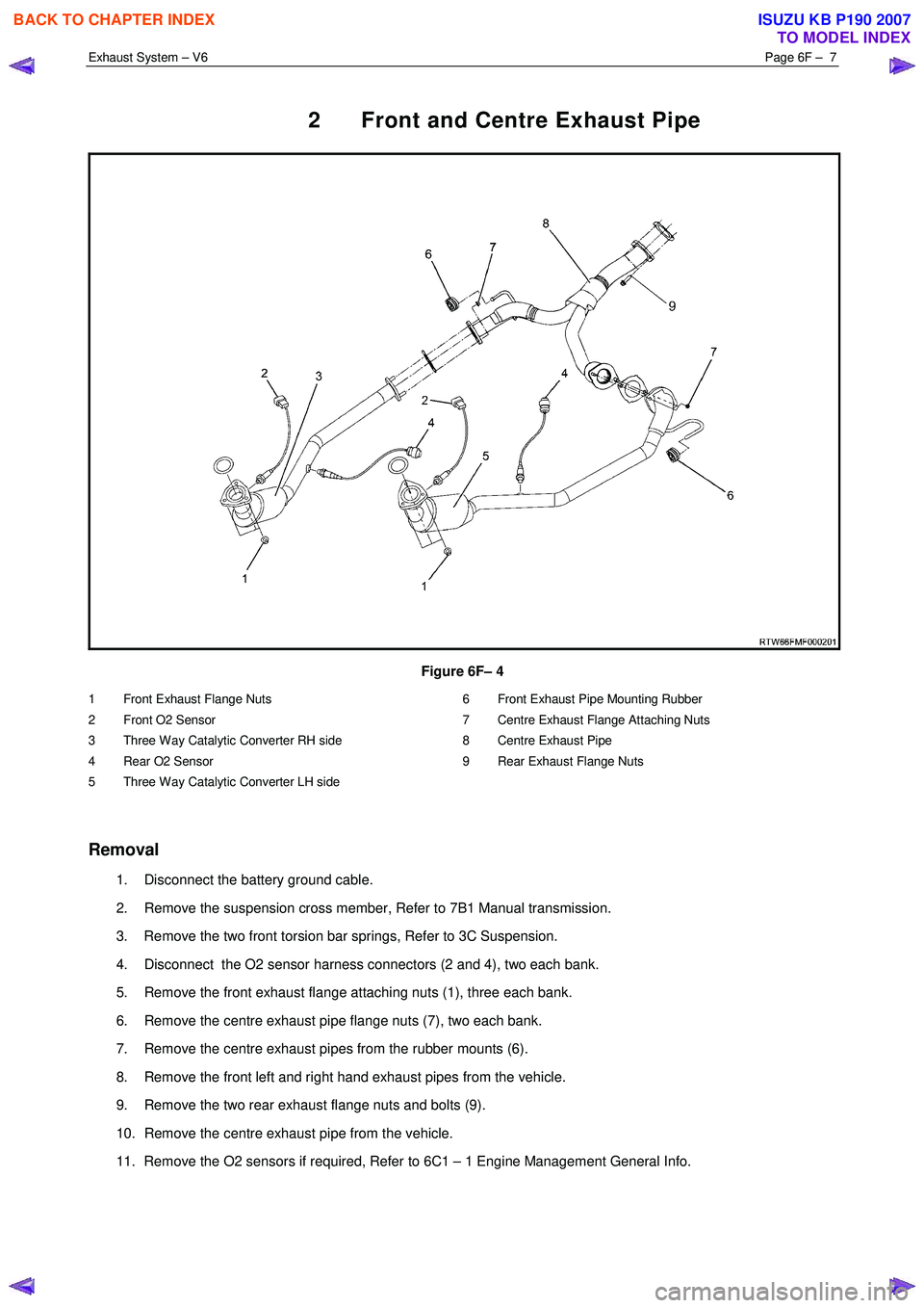
2 Front and Centre Exhaust Pipe
Figure 6F– 4
1 Front Exhaust Flange Nuts
2 Front O2 Sensor
3 Three Way Catalytic Converter RH side
4 Rear O2 Sensor
5 Three Way Catalytic Converter LH side 6 Front Exhaust Pipe Mounting Rubber
7 Centre Exhaust Flange Attaching Nuts
8 Centre Exhaust Pipe
9 Rear Exhaust Flange Nuts
Removal
1. Disconnect the battery ground cable.
2. Remove the suspension cross member, Refer to 7B1 Manual transmission.
3. Remove the two front torsion bar springs, Refer to 3C Suspension.
4. Disconnect the O2 sensor harness connectors (2 and 4), two each bank.
5. Remove the front exhaust flange attaching nuts (1), three each bank.
6. Remove the centre exhaust pipe flange nuts (7), two each bank.
7. Remove the centre exhaust pipes from the rubber mounts (6).
8. Remove the front left and right hand exhaust pipes from the vehicle.
9. Remove the two rear exhaust flange nuts and bolts (9).
10. Remove the centre exhaust pipe from the vehicle.
11. Remove the O2 sensors if required, Refer to 6C1 – 1 Engine Management General Info.
BACK TO CHAPTER INDEX
TO MODEL INDEX
ISUZU KB P190 2007
Page 3756 of 6020
Exhaust System – V6 Page 6F – 8
NOTE:
• Support the exhaust system at all times.
• Clean the threads of the attaching bolts, nuts,
studs and flanges with a suitable cleaning
solvent.
• Apply a high temperature anti-seize
compound to the manifold front pipe flange
joint studs, then align the flange over the
studs.
Reinstallation
1. Install any removed O2 sensors, Refer to 6C1 – 1 Engine Management General Info.
2. Position the centre exhaust pipe into location under the vehicle.
3. Install the two rear exhaust flange nuts and bolts (9).
4. Position the front exhaust pipes into location under the vehicle.
5. Install the centre exhaust pipes into the rubber mounts (6).
6. Install the exhaust flange fixing nuts (1), three each bank.
7. Install the rear exhaust pipe flange nuts (7), two each bank.
8. Reconnect the O2 sensor harness connectors (4), two each bank.
9. Install the two front torsion bar springs, Refer to 3C Suspension.
10. Install the suspension cross member, Refer to 7B1 Manual transmission.
11. Reconnect the battery ground cable.
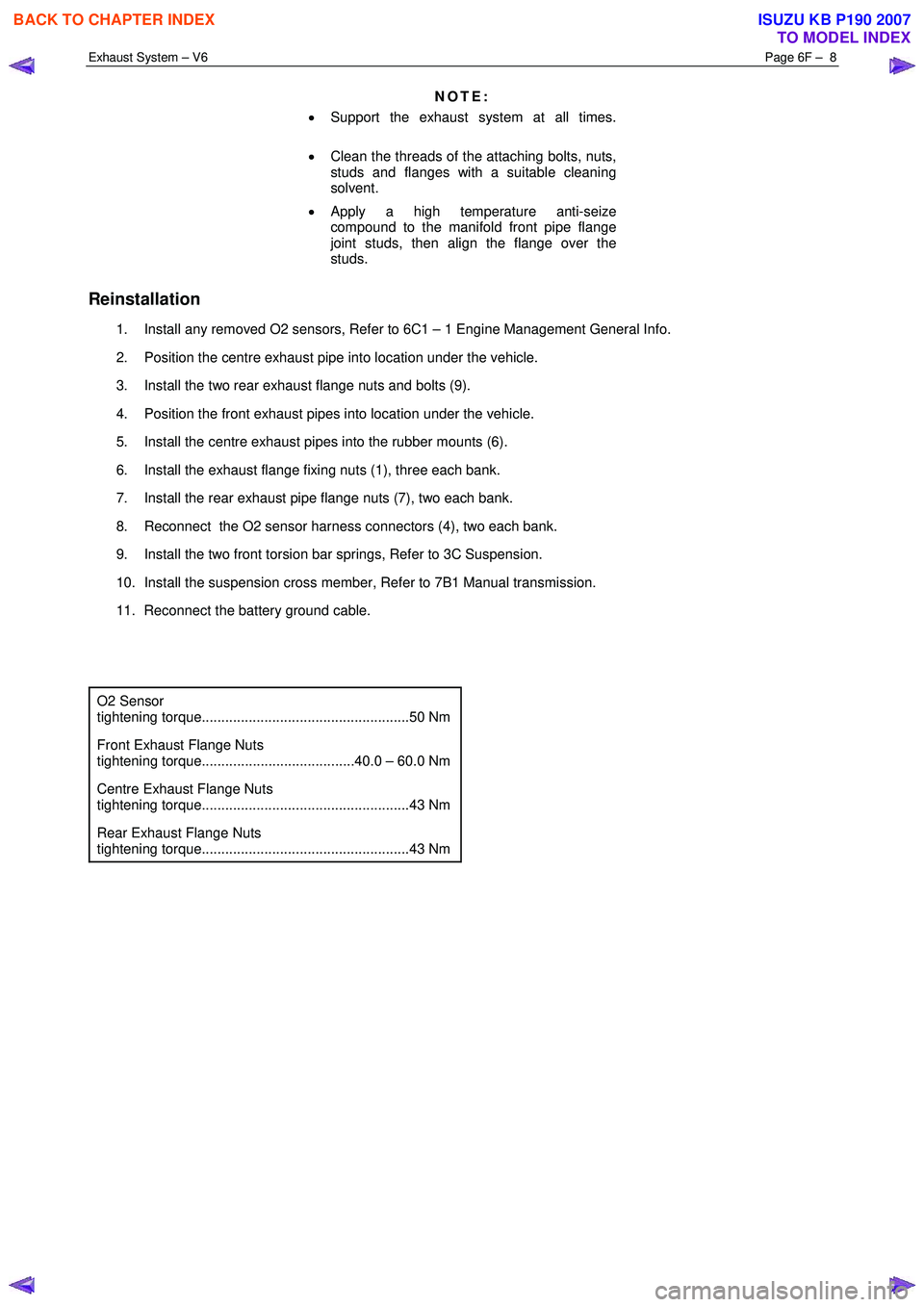
O2 Sensor
tightening torque.....................................................50 Nm
Front Exhaust Flange Nuts
tightening torque.......................................40.0 – 60.0 Nm
Centre Exhaust Flange Nuts
tightening torque.....................................................43 Nm
Rear Exhaust Flange Nuts
tightening torque.....................................................43 Nm
BACK TO CHAPTER INDEX
TO MODEL INDEX
ISUZU KB P190 2007
Page 4389 of 6020
TRANSMISSION CONTROL SYSTEM (JR405E) 7A2-105
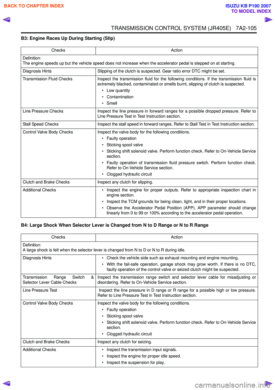
B3: Engine Races Up During Starting (Slip)
B4: Large Shock When Selector Lever is Changed from N to D Range or N to R Range
Checks Action
Definition:
The engine speeds up but the vehicle speed does not increase when the accelerator pedal is stepped on at starting.
Diagnosis Hints Slipping of the clutch is suspected. Gear ratio error DTC might be set.
Transmission Fluid Checks Inspect the transmission fluid for the following conditions. If the transmission fluid is
extremely blacked, contaminated or smells burnt, slipping of clutch is suspected.
• Low quantity
• Contamination
•Smell
Line Pressure Checks Inspect the line pressure in forward ranges for a possible dropped pressure. Refer to
Line Pressure Test in Test Instruction section.
Stall Speed Checks Inspect the stall speed in forward ranges. Refer to Stall Test in Test Instruction section.
Control Valve Body Checks Inspect the valve body for the following conditions.
• Faulty operation
• Sticking spool valve
• Sticking shift solenoid valve. Perform function check. Refer to On-Vehicle Service section.
• Faulty operation of transmission fluid pressure switch. Perform function check. Refer to On-Vehicle Service section.
• Clogged hydraulic circuit
Clutch and Brake Checks Inspect any clutch for slipping.
Additional Checks • Inspect the engine for proper outputs. Refer to appropriate inspection chart in
engine section.
• Inspect the TCM grounds for being clean, tight, and in their proper locations.
• Observe the Accelerator Pedal Position (APP). APP parameter should change linearly from 0 to 99 or 100% according to the accelerator pedal operation.
Checks Action
Definition:
A large shock is felt when the selector lever is changed from N to D or N to R during idle.
Diagnosis Hints • Check the vehicle side such as exhaust mounting and engine mounting.
• With the fail-safe operation, garage shock may grow worth. If there is no DTC, faulty operation of the control valve or seized clutch might be suspected.
Transmission Range Switch &
Selector Lever Cable Checks Inspect the transmission range switch and selector lever cable for misadjusting or
disordering. Refer to On-Vehicle Service section.
Line Pressure Test Inspect the line pressure in D range or R range for a possible high or low pressure.
Refer to Line Pressure Test in Test Instruction section.
Control Valve Body Checks Inspect the valve body for the following conditions.
• Faulty operation
• Sticking spool valve
• Sticking shift solenoid valve. Perform function check. Refer to On-Vehicle Service section.
• Clogged hydraulic circuit
Clutch and Brake Checks Inspect any clutch for seizing.
Additional Checks • Inspect the transmission input signals.
• Inspect the engine for proper idle speed.
• Inspect the suspension for play.
BACK TO CHAPTER INDEX
TO MODEL INDEX
ISUZU KB P190 2007