2007 ISUZU KB P190 suspension
[x] Cancel search: suspensionPage 1435 of 6020
ENGINE MECHANICAL (4JK1/4JJ1) 6A-75
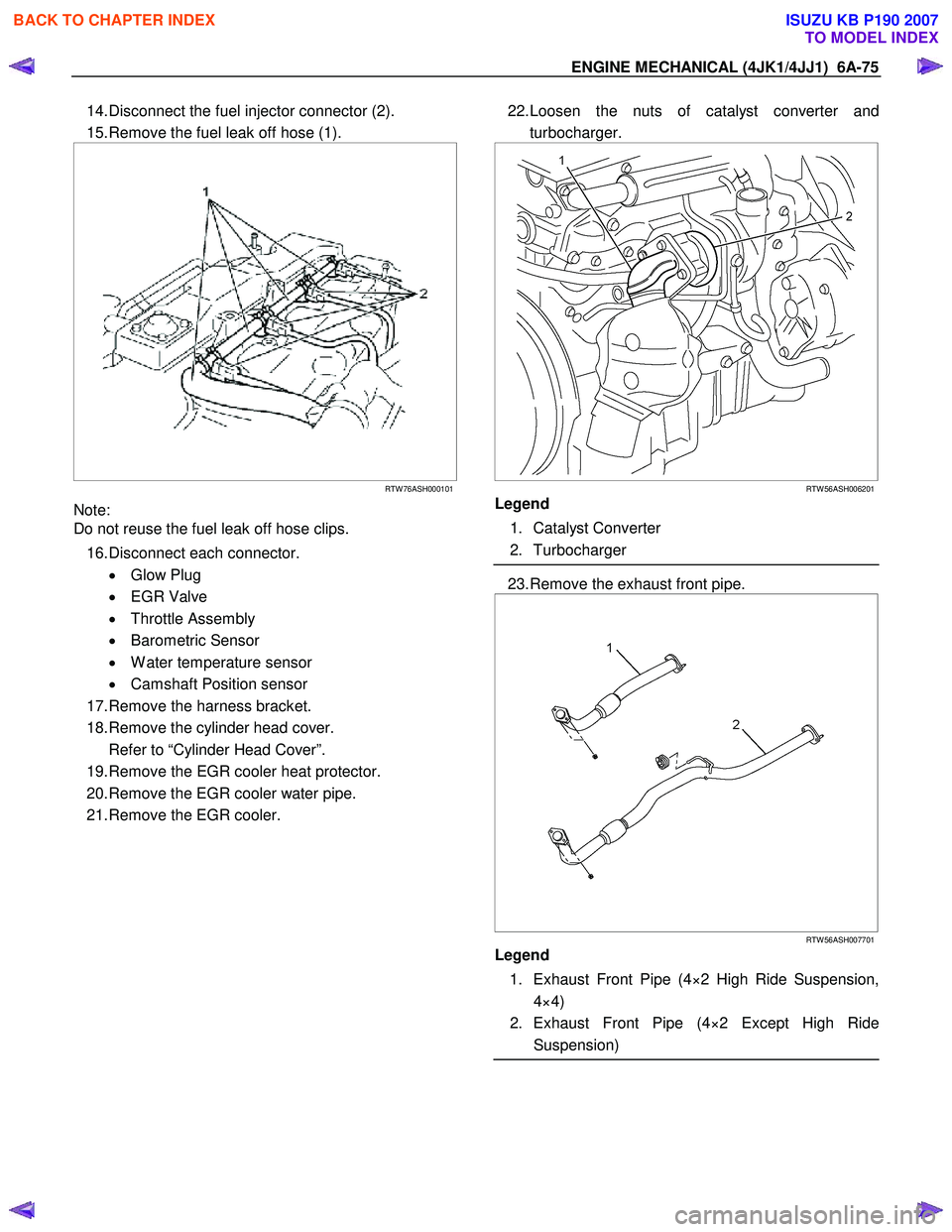
14. Disconnect the fuel injector connector (2).
15. Remove the fuel leak off hose (1).
RTW 76ASH000101
Note:
Do not reuse the fuel leak off hose clips.
16. Disconnect each connector. • Glow Plug
• EGR Valve
• Throttle Assembly
• Barometric Sensor
• W ater temperature sensor
• Camshaft Position sensor
17. Remove the harness bracket.
18. Remove the cylinder head cover.
Refer to “Cylinder Head Cover”.
19. Remove the EGR cooler heat protector.
20. Remove the EGR cooler water pipe.
21. Remove the EGR cooler.
22. Loosen the nuts of catalyst converter and
turbocharger.
RTW 56ASH006201
Legend
1. Catalyst Converter
2. Turbocharger
23. Remove the exhaust front pipe.
RTW 56ASH007701
Legend
1. Exhaust Front Pipe (4×2 High Ride Suspension, 4×4)
2. Exhaust Front Pipe (4×2 Except High Ride Suspension)
BACK TO CHAPTER INDEX
TO MODEL INDEX
ISUZU KB P190 2007
Page 1987 of 6020
6F-2 EXHAUST SYSTEM (4JK1/4JJ1)
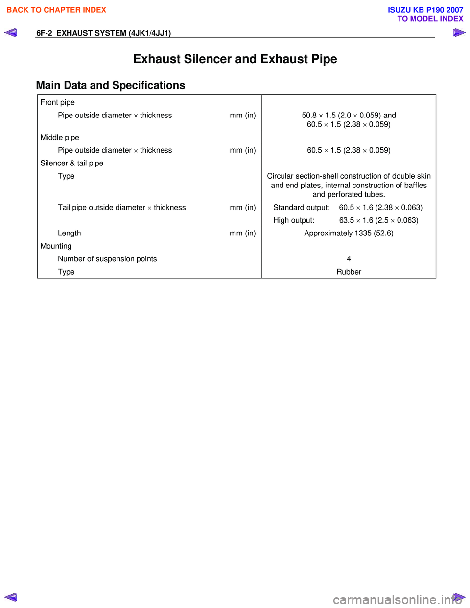
Exhaust Silencer and Exhaust Pipe
Main Data and Specifications
Front pipe
Pipe outside diameter × thickness mm (in)50.8 × 1.5 (2.0 × 0.059) and
60.5 × 1.5 (2.38 × 0.059)
Middle pipe
Pipe outside diameter × thickness mm (in)60.5 × 1.5 (2.38 × 0.059)
Silencer & tail pipe
Type Circular section-shell construction of double skin
and end plates, internal construction of baffles and perforated tubes.
Tail pipe outside diameter × thickness mm (in) Standard output: 60.5 × 1.6 (2.38 × 0.063)
High output: 63.5 × 1.6 (2.5 × 0.063)
Length mm (in)Approximately 1335 (52.6)
Mounting
Number of suspension points 4
Type Rubber
BACK TO CHAPTER INDEX
TO MODEL INDEX
ISUZU KB P190 2007
Page 1988 of 6020
EXHAUST SYSTEM (4JK1/4JJ1) 6F-3
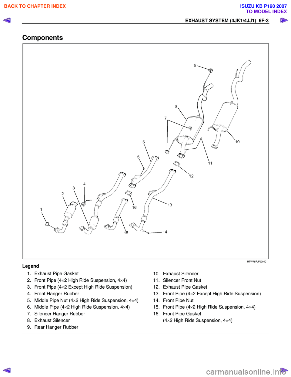
Components
RTW 76FLF000101
Legend
1. Exhaust Pipe Gasket
2. Front Pipe (4 ×2 High Ride Suspension, 4 ×4)
3. Front Pipe (4 ×2 Except High Ride Suspension)
4. Front Hanger Rubber
5. Middle Pipe Nut (4 ×2 High Ride Suspension, 4 ×4)
6. Middle Pipe (4 ×2 High Ride Suspension, 4 ×4)
7. Silencer Hanger Rubber
8. Exhaust Silencer
9. Rear Hanger Rubber
10. Exhaust Silencer
11. Silencer Front Nut
12. Exhaust Pipe Gasket
13. Front Pipe (4 ×2 Except High Ride Suspension)
14. Front Pipe Nut
15. Front Pipe (4 ×2 High Ride Suspension, 4 ×4)
16. Front Pipe Gasket
(4 ×2 High Ride Suspension, 4 ×4)
BACK TO CHAPTER INDEX
TO MODEL INDEX
ISUZU KB P190 2007
Page 1989 of 6020
6F-4 EXHAUST SYSTEM (4JK1/4JJ1)
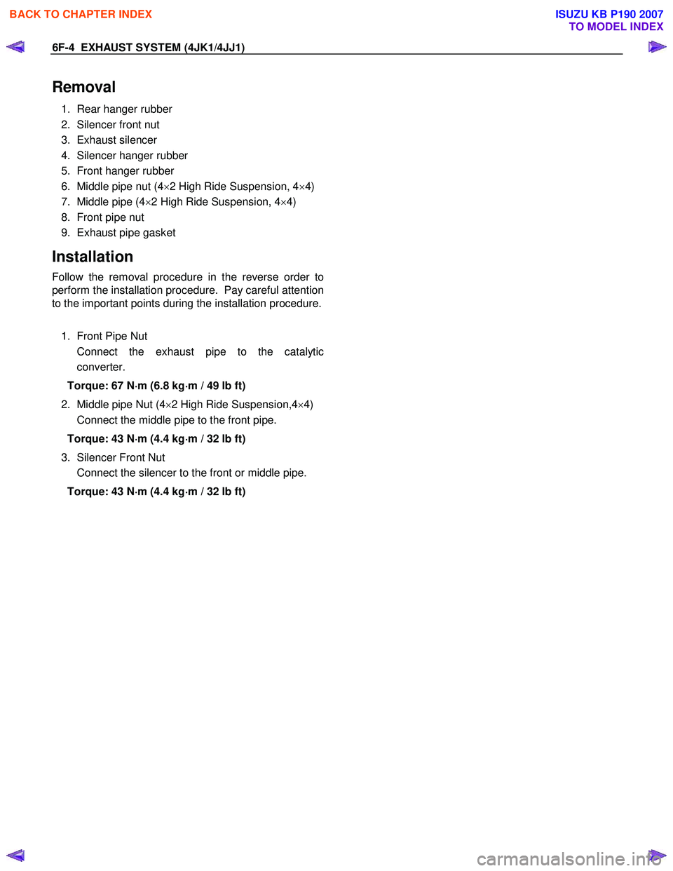
Removal
1. Rear hanger rubber
2. Silencer front nut
3. Exhaust silencer
4. Silencer hanger rubber
5. Front hanger rubber
6. Middle pipe nut (4 ×2 High Ride Suspension, 4 ×4)
7. Middle pipe (4 ×2 High Ride Suspension, 4 ×4)
8. Front pipe nut
9. Exhaust pipe gasket
Installation
Follow the removal procedure in the reverse order to
perform the installation procedure. Pay careful attention
to the important points during the installation procedure.
1. Front Pipe Nut
Connect the exhaust pipe to the catalytic converter.
Torque: 67 N ⋅
⋅⋅
⋅
m (6.8 kg ⋅
⋅⋅
⋅
m / 49 lb ft)
2. Middle pipe Nut (4 ×2 High Ride Suspension,4 ×4)
Connect the middle pipe to the front pipe.
Torque: 43 N ⋅
⋅⋅
⋅
m (4.4 kg ⋅
⋅⋅
⋅
m / 32 lb ft)
3. Silencer Front Nut
Connect the silencer to the front or middle pipe.
Torque: 43 N ⋅
⋅⋅
⋅
m (4.4 kg ⋅
⋅⋅
⋅
m / 32 lb ft)
BACK TO CHAPTER INDEX
TO MODEL INDEX
ISUZU KB P190 2007
Page 2234 of 6020
6E–64 ENGINE DRIVEABILITY AND EMISSIONS
– Are there areas subjected to vibration ormovement (engine, transmission or
suspension)?
– Are there areas exposed to moisture, road salt or other corrosives (battery acid, oil or other
fluids)?
– Are there common mounting areas with other systems/components?
– Have previous repairs been performed to wiring, connectors, components or mounting areas
(causing pinched wires between panels and
drivetrain or suspension components without
causing and immediate problem)?
– Does the vehicle have aftermarket or dealer- installed equipment (radios, telephone, etc.)
Step 2: Isolate the problem
At this point, you should have a good idea of what could
cause the present condition, as well as could not cause
the condition. Actions to take include the following:
• Divide (and separate, where possible) the system or circuit into smaller sections
• Confine the problem to a smaller area of the vehicle (start with main harness connections while removing
panels and trim as necessary in order to eliminate
large vehicle sections from further investigation)
• For two or more circuits that do not share a common power or ground, concentrate on areas where
harnesses are routed together or connectors are
shared (refer to the following hints)
Hints
Though the symptoms may vary, basic electrical failures
are generally caused by:
• Loose connections: – Open/high resistance in terminals, splices,connectors or grounds
• Incorrect connector/harness routing (usually in new vehicles or after a repair has been made):
– Open/high resistance in terminals, splices, connectors of grounds
• Corrosion and wire damage:
– Open/high resistance in terminals, splices,connectors of grounds
• Component failure: – Opens/short and high resistance in relays,modules, switches or loads
• Aftermarket equipment affecting normal operation of other systems
You may isolate circuits by:
• Unplugging connectors or removing a fuse to separate one part of the circuit from another part
• Operating shared circuits and eliminating those that function normally from the suspect circuit
• If only one component fails to operate, begin testing at the component
• If a number of components do no operate, begin tests at the area of commonality (such as power sources,
ground circuits, switches or major connectors)
What resources you should use
Whenever appropriate, you should use the following
resources to assist in the diagnostic process:
• Service manual
• Technical equipment (for data analysis)
• Experience
• Technical Assistance
• Circuit testing tools
5d. Intermittent Diagnosis
By definition, an intermittent problem is one that does
not occur continuously and will occur when certain
conditions are met. All these conditions, however, may
not be obvious or currently known. Generally,
intermittents are caused by:
• Faulty electrical connections and wiring
• Malfunctioning components (such as sticking relays, solenoids, etc.)
• EMI/RFI (Electromagnetic/radio frequency interference)
• Aftermarket equipment
Intermittent diagnosis requires careful analysis of
suspected systems to help prevent replacing good
parts. This may involve using creativity and ingenuity to
interpret customer complaints and simulating all
external and internal system conditions to duplicate the
problem.
What you should do
Step 1: Acquire information
A thorough and comprehensive customer check sheet
is critical to intermittent problem diagnosis. You should
require this, since it will dictate the diagnostic starting
point. The vehicle service history file is another
source for accumulating information about the
complaint.
Step 2: Analyze the intermittent problem
Analyze the customer check sheet and service history
file to determine conditions relevant to the suspect
system(s).
Using service manual information, you must identify,
trace and locate all electrical circuits related to the
malfunctioning system(s). If there is more than one
system failure, you should identify, trace and locate
areas of commonality shared by the suspect circuits.
BACK TO CHAPTER INDEX
TO MODEL INDEX
ISUZU KB P190 2007
Page 2463 of 6020
6F-14 ENGINE EXHAUST
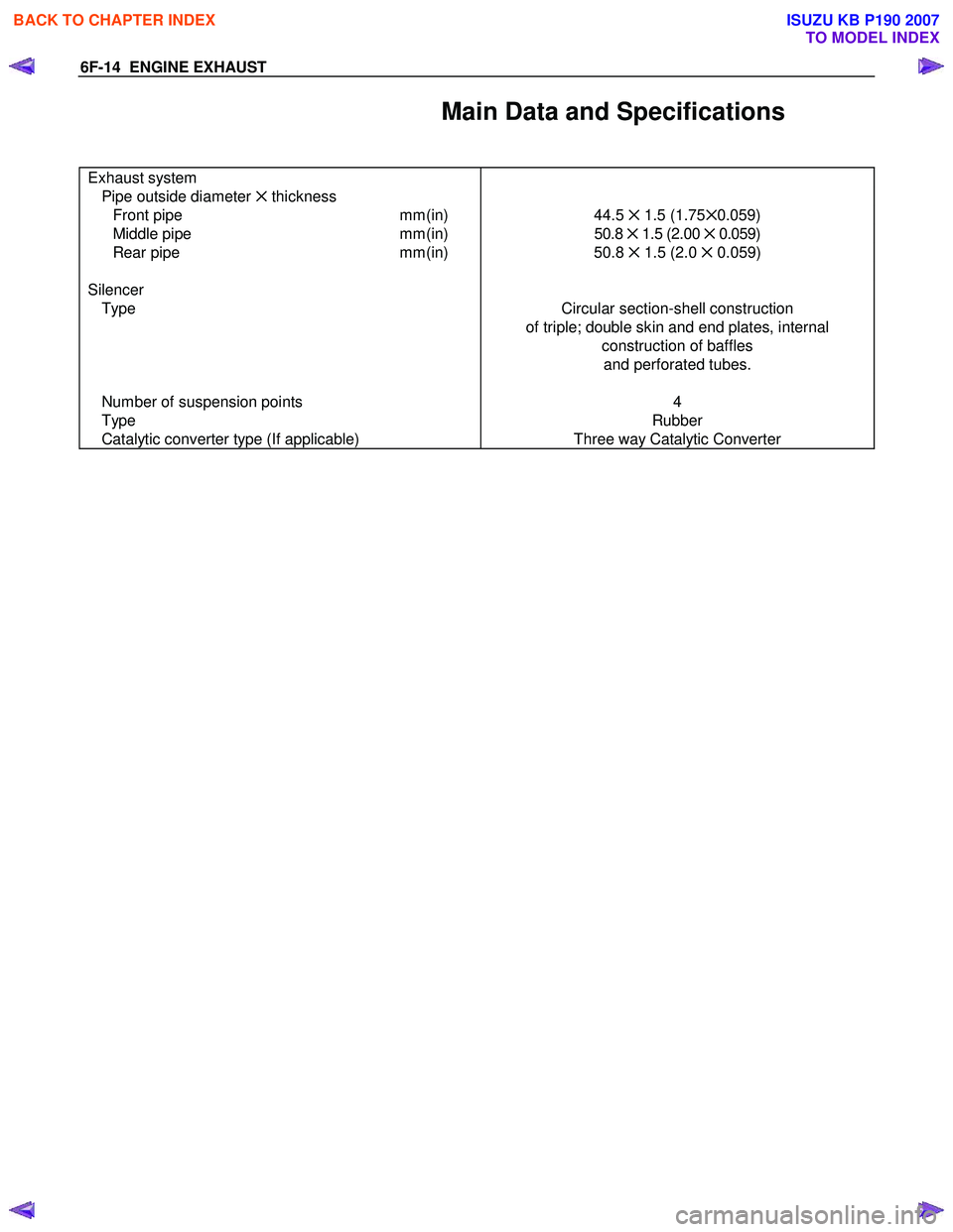
Main Data and Specifications
Exhaust system
Pipe outside diameter ✕ thickness
Front pipe mm(in) 44.5 ✕ 1.5 (1.75 ✕0.059)
Middle pipe mm(in) 50.8 ✕ 1.5 (2.00 ✕ 0.059)
Rear pipe mm(in) 50.8 ✕ 1.5 (2.0 ✕ 0.059)
Silencer
Type Circular section-shell construction
of triple; double skin and end plates, internal construction of baffles and perforated tubes.
Number of suspension points
Type
Catalytic converter type (If applicable) 4
Rubber
Three way Catalytic Converter
BACK TO CHAPTER INDEX
TO MODEL INDEX
ISUZU KB P190 2007
Page 2522 of 6020
Engine Mechanical – V6 Page 6A1–43
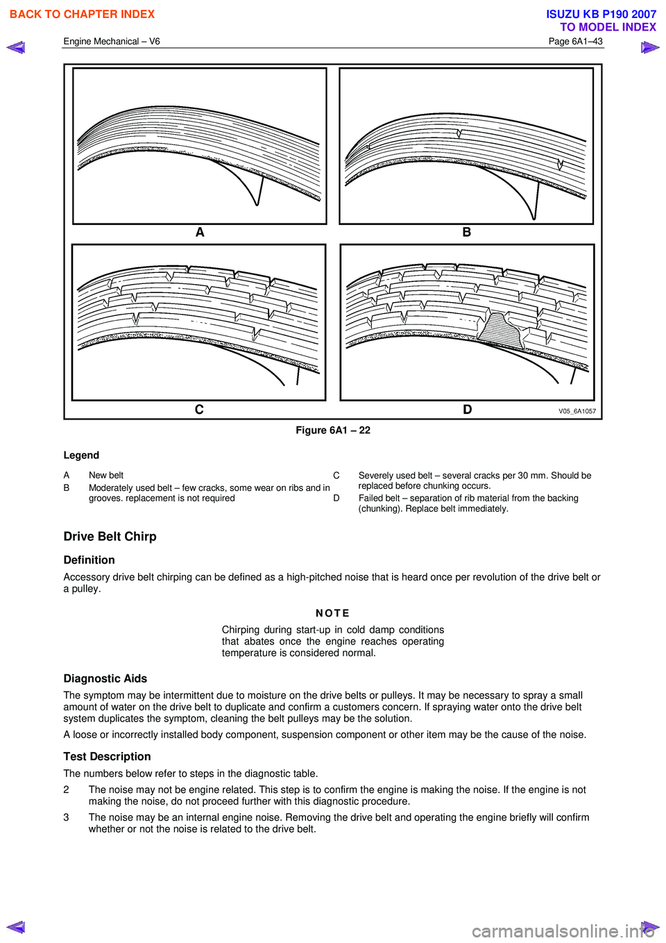
Figure 6A1 – 22
Legend
A New belt
B Moderately used belt – few cra cks, some wear on ribs and in
grooves. replacement is not required C Severely used belt – several cracks per 30 mm. S
hould be
replaced before chunking occurs.
D Failed belt – separation of rib material from the backing (chunking). Replace belt immediately.
Drive Belt Chirp
Definition
Accessory drive belt chirping can be defined as a high-pitched noise that is heard once per revolution of the drive belt or
a pulley.
NOTE
Chirping during start-up in cold damp conditions
that abates once the engine reaches operating
temperature is considered normal.
Diagnostic Aids
The symptom may be intermittent due to moisture on the drive belts or pulleys. It may be necessary to spray a small
amount of water on the drive belt to duplicate and confirm a customers concern. If spraying water onto the drive belt
system duplicates the symptom, cleaning the belt pulleys may be the solution.
A loose or incorrectly installed body component, suspension component or other item may be the cause of the noise.
Test Description
The numbers below refer to steps in the diagnostic table.
2 The noise may not be engine related. This step is to confirm the engine is making the noise. If the engine is not making the noise, do not proceed further with this diagnostic procedure.
3 The noise may be an internal engine noise. Removing the drive belt and operating the engine briefly will confirm whether or not the noise is related to the drive belt.
BACK TO CHAPTER INDEX
TO MODEL INDEX
ISUZU KB P190 2007
Page 2524 of 6020
Engine Mechanical – V6 Page 6A1–45
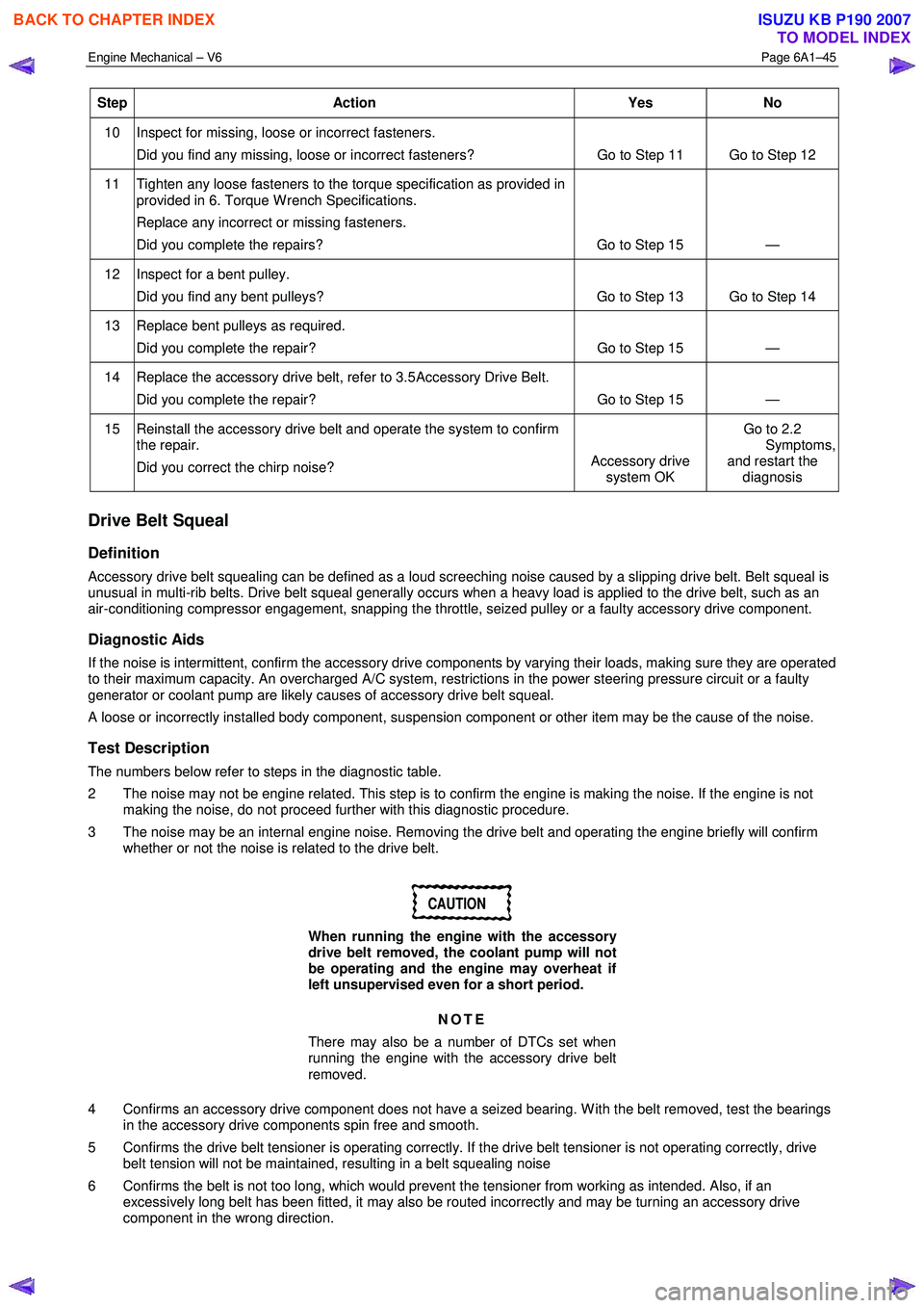
Step Action Yes No
10 Inspect for missing, loose or incorrect fasteners.
Did you find any missing, loose or incorrect fasteners? Go to Step 11 Go to Step 12
11 Tighten any loose fasteners to the torque specification as provided in
provided in 6. Torque W rench Specifications.
Replace any incorrect or missing fasteners.
Did you complete the repairs? Go to Step 15 —
12 Inspect for a bent pulley. Did you find any bent pulleys? Go to Step 13 Go to Step 14
13 Replace bent pulleys as required. Did you complete the repair? Go to Step 15 —
14 Replace the accessory drive belt, refer to 3.5 Accessory Drive Belt.
Did you complete the repair? Go to Step 15 —
15 Reinstall the accessory drive belt and operate the system to confirm the repair.
Did you correct the chirp noise? Accessory drive
system OK Go to 2.2
Symptoms, and restart the
diagnosis
Drive Belt Squeal
Definition
Accessory drive belt squealing can be defined as a loud screeching noise caused by a slipping drive belt. Belt squeal is
unusual in multi-rib belts. Drive belt squeal generally occurs when a heavy load is applied to the drive belt, such as an
air-conditioning compressor engagement, snapping the throttle, seized pulley or a faulty accessory drive component.
Diagnostic Aids
If the noise is intermittent, confirm the accessory drive components by varying their loads, making sure they are operated
to their maximum capacity. An overcharged A/C system, restrictions in the power steering pressure circuit or a faulty
generator or coolant pump are likely causes of accessory drive belt squeal.
A loose or incorrectly installed body component, suspension component or other item may be the cause of the noise.
Test Description
The numbers below refer to steps in the diagnostic table.
2 The noise may not be engine related. This step is to confirm the engine is making the noise. If the engine is not making the noise, do not proceed further with this diagnostic procedure.
3 The noise may be an internal engine noise. Removing the drive belt and operating the engine briefly will confirm whether or not the noise is related to the drive belt.
CAUTION
When running the engine with the accessory
drive belt removed, the coolant pump will not
be operating and the engine may overheat if
left unsupervised even for a short period.
NOTE
There may also be a number of DTCs set when
running the engine with the accessory drive belt
removed.
4 Confirms an accessory drive component does not have a seized bearing. W ith the belt removed, test the bearings in the accessory drive components spin free and smooth.
5 Confirms the drive belt tensioner is operating correctly. If the drive belt tensioner is not operating correctly, drive belt tension will not be maintained, resulting in a belt squealing noise
6 Confirms the belt is not too long, which would prevent the tensioner from working as intended. Also, if an excessively long belt has been fitted, it may also be routed incorrectly and may be turning an accessory drive
component in the wrong direction.
BACK TO CHAPTER INDEX
TO MODEL INDEX
ISUZU KB P190 2007