2007 ISUZU KB P190 check engine
[x] Cancel search: check enginePage 1159 of 6020
Engine Control System (4JH1) 6E-125
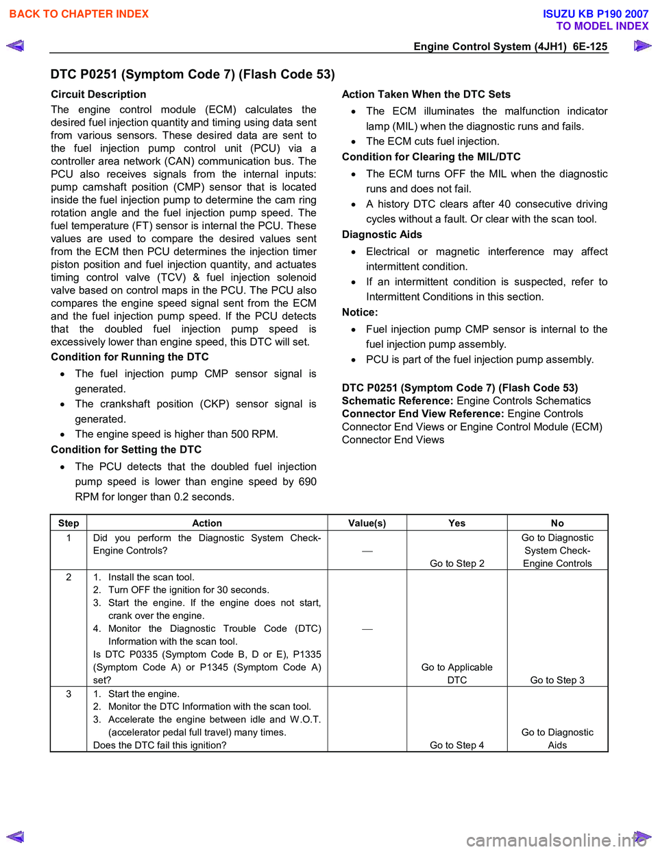
DTC P0251 (Symptom Code 7) (Flash Code 53)
Circuit Description
The engine control module (ECM) calculates the
desired fuel injection quantity and timing using data sent
from various sensors. These desired data are sent to
the fuel injection pump control unit (PCU) via a
controller area network (CAN) communication bus. The
PCU also receives signals from the internal inputs:
pump camshaft position (CMP) sensor that is located
inside the fuel injection pump to determine the cam ring
rotation angle and the fuel injection pump speed. The
fuel temperature (FT) sensor is internal the PCU. These
values are used to compare the desired values sent
from the ECM then PCU determines the injection time
r
piston position and fuel injection quantity, and actuates
timing control valve (TCV) & fuel injection solenoid
valve based on control maps in the PCU. The PCU also
compares the engine speed signal sent from the ECM
and the fuel injection pump speed. If the PCU detects
that the doubled fuel injection pump speed is
excessively lower than engine speed, this DTC will set.
Condition for Running the DTC
• The fuel injection pump CMP sensor signal is
generated.
• The crankshaft position (CKP) sensor signal is
generated.
• The engine speed is higher than 500 RPM.
Condition for Setting the DTC
• The PCU detects that the doubled fuel injection
pump speed is lower than engine speed by 690
RPM for longer than 0.2 seconds.
Action Taken When the DTC Sets
• The ECM illuminates the malfunction indicato
r
lamp (MIL) when the diagnostic runs and fails.
• The ECM cuts fuel injection.
Condition for Clearing the MIL/DTC
• The ECM turns OFF the MIL when the diagnostic
runs and does not fail.
• A history DTC clears after 40 consecutive driving
cycles without a fault. Or clear with the scan tool.
Diagnostic Aids
• Electrical or magnetic interference may affect
intermittent condition.
• If an intermittent condition is suspected, refer to
Intermittent Conditions in this section.
Notice:
• Fuel injection pump CMP sensor is internal to the
fuel injection pump assembly.
• PCU is part of the fuel injection pump assembly.
DTC P0251 (Symptom Code 7) (Flash Code 53)
Schematic Reference: Engine Controls Schematics
Connector End View Reference: Engine Controls
Connector End Views or Engine Control Module (ECM)
Connector End Views
Step Action Value(s) Yes No
1 Did you perform the Diagnostic System Check-
Engine Controls?
Go to Step 2 Go to Diagnostic
System Check-
Engine Controls
2 1. Install the scan tool. 2. Turn OFF the ignition for 30 seconds.
3. Start the engine. If the engine does not start, crank over the engine.
4. Monitor the Diagnostic Trouble Code (DTC) Information with the scan tool.
Is DTC P0335 (Symptom Code B, D or E), P1335
(Symptom Code A) or P1345 (Symptom Code A)
set?
Go to Applicable DTC Go to Step 3
3 1. Start the engine. 2. Monitor the DTC Information with the scan tool.
3. Accelerate the engine between idle and W .O.T. (accelerator pedal full travel) many times.
Does the DTC fail this ignition?
Go to Step 4 Go to Diagnostic
Aids
BACK TO CHAPTER INDEX
TO MODEL INDEX
ISUZU KB P190 2007
Page 1160 of 6020
6E-126 Engine Control System (4JH1)
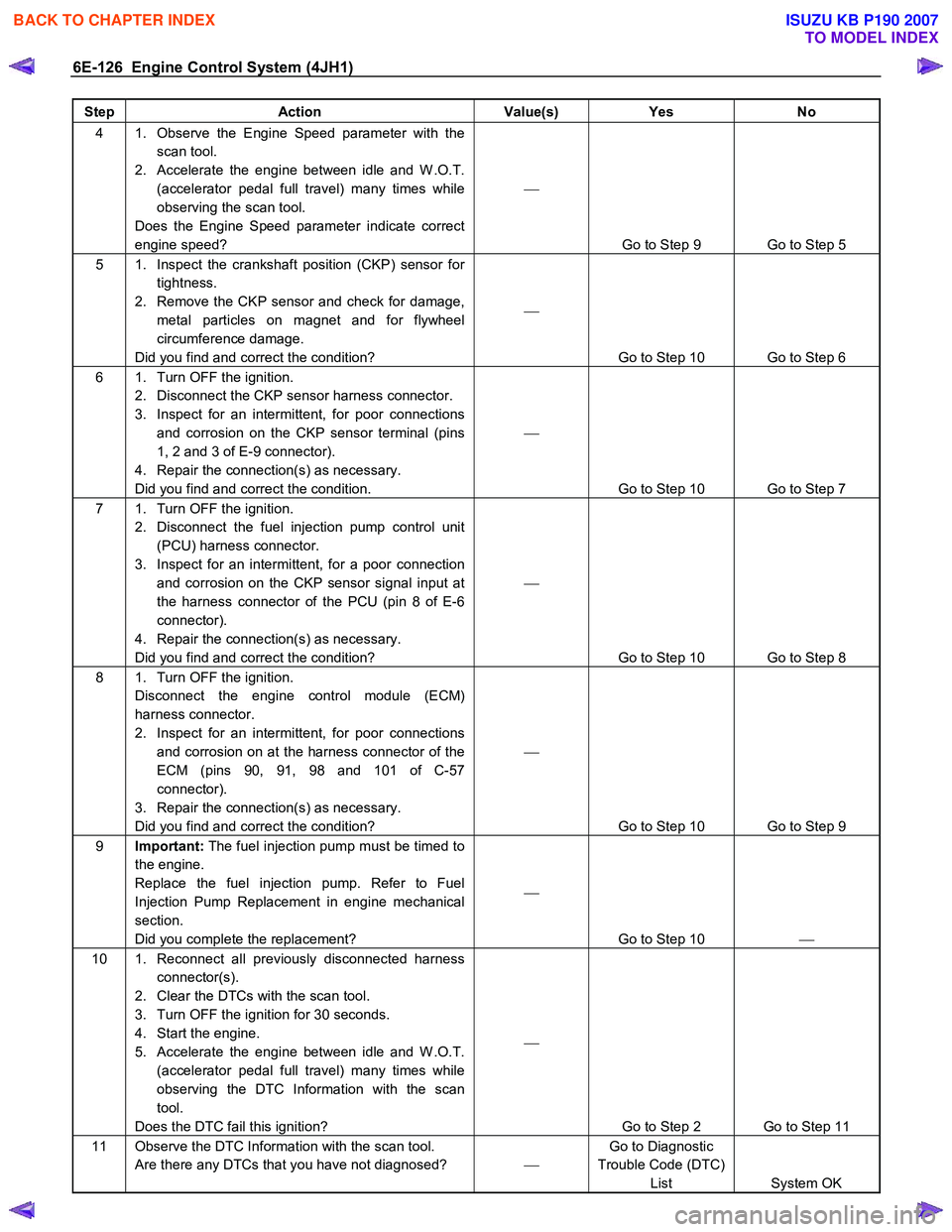
Step Action Value(s) Yes No
4 1. Observe the Engine Speed parameter with the
scan tool.
2. Accelerate the engine between idle and W .O.T. (accelerator pedal full travel) many times while
observing the scan tool.
Does the Engine Speed parameter indicate correct
engine speed?
Go to Step 9 Go to Step 5
5 1. Inspect the crankshaft position (CKP) sensor for tightness.
2. Remove the CKP sensor and check for damage, metal particles on magnet and for flywheel
circumference damage.
Did you find and correct the condition?
Go to Step 10 Go to Step 6
6 1. Turn OFF the ignition.
2. Disconnect the CKP sensor harness connector.
3. Inspect for an intermittent, for poor connections and corrosion on the CKP sensor terminal (pins
1, 2 and 3 of E-9 connector).
4. Repair the connection(s) as necessary.
Did you find and correct the condition.
Go to Step 10 Go to Step 7
7 1. Turn OFF the ignition. 2. Disconnect the fuel injection pump control unit (PCU) harness connector.
3. Inspect for an intermittent, for a poor connection and corrosion on the CKP sensor signal input at
the harness connector of the PCU (pin 8 of E-6
connector).
4. Repair the connection(s) as necessary.
Did you find and correct the condition?
Go to Step 10 Go to Step 8
8 1. Turn OFF the ignition. Disconnect the engine control module (ECM)
harness connector.
2. Inspect for an intermittent, for poor connections and corrosion on at the harness connector of the
ECM (pins 90, 91, 98 and 101 of C-57
connector).
3. Repair the connection(s) as necessary.
Did you find and correct the condition?
Go to Step 10 Go to Step 9
9 Important: The fuel injection pump must be timed to
the engine.
Replace the fuel injection pump. Refer to Fuel
Injection Pump Replacement in engine mechanical
section.
Did you complete the replacement?
Go to Step 10
10 1. Reconnect all previously disconnected harness
connector(s).
2. Clear the DTCs with the scan tool.
3. Turn OFF the ignition for 30 seconds.
4. Start the engine.
5. Accelerate the engine between idle and W .O.T. (accelerator pedal full travel) many times while
observing the DTC Information with the scan
tool.
Does the DTC fail this ignition?
Go to Step 2 Go to Step 11
11 Observe the DTC Information with the scan tool. Are there any DTCs that you have not diagnosed? Go to Diagnostic
Trouble Code (DTC) List System OK
BACK TO CHAPTER INDEX
TO MODEL INDEX
ISUZU KB P190 2007
Page 1161 of 6020
Engine Control System (4JH1) 6E-127
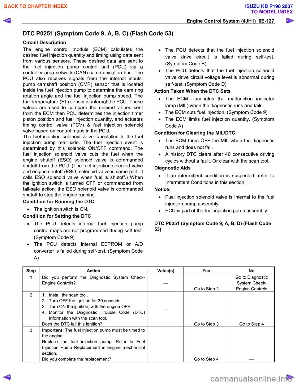
DTC P0251 (Symptom Code 9, A, B, C) (Flash Code 53)
Circuit Description
The engine control module (ECM) calculates the
desired fuel injection quantity and timing using data sent
from various sensors. These desired data are sent to
the fuel injection pump control unit (PCU) via a
controller area network (CAN) communication bus. The
PCU also receives signals from the internal inputs:
pump camshaft position (CMP) sensor that is located
inside the fuel injection pump to determine the cam ring
rotation angle and the fuel injection pump speed. The
fuel temperature (FT) sensor is internal the PCU. These
values are used to compare the desired values sent
from the ECM then PCU determines the injection time
r
piston position and fuel injection quantity, and actuates
timing control valve (TCV) & fuel injection solenoid
valve based on control maps in the PCU.
The fuel injection solenoid valve is installed to the fuel
injection pump rear side. The fuel injection event is
determined by this solenoid ON/OFF command. The
fuel injection solenoid valve cuts the fuel when the
engine shutoff (ESO) solenoid valve is commanded
shutoff from the PCU. (The fuel injection solenoid valve
and engine shutoff (ESO) solenoid valve is same part. It
calls ESO solenoid valve when fuel is shutoff.) W hen
the ignition switch is turned OFF or commanded from
fail-safe action, the ESO solenoid valve is commanded
shutoff to stop the engine running.
Condition for Running the DTC
• The ignition switch is ON.
Condition for Setting the DTC
• The PCU detects internal fuel injection pump
control maps are not programmed during self-test.
(Symptom Code 9)
• The PCU detects internal EEPROM or A/D
converter is failed during self-test. (Symptom Code
A)
• The PCU detects that the fuel injection solenoid
valve drive circuit is failed during self-test.
(Symptom Code B)
• The PCU detects that the fuel injection solenoid
valve drive circuit voltage level is abnormal during
self-test. (Symptom Code D)
Action Taken When the DTC Sets
• The ECM illuminates the malfunction indicato
r
lamp (MIL) when the diagnostic runs and fails.
• The ECM cuts fuel injection. (Symptom Code 9)
• The ECM limits fuel injection quantity. (Symptom
Code A)
Condition for Clearing the MIL/DTC
• The ECM turns OFF the MIL when the diagnostic
runs and does not fail.
• A history DTC clears after 40 consecutive driving
cycles without a fault. Or clear with the scan tool.
Diagnostic Aids
• If an intermittent condition is suspected, refer to
Intermittent Conditions in this section.
Notice:
• Fuel injection solenoid valve is internal to the fuel
injection pump assembly.
• PCU is part of the fuel injection pump assembly.
DTC P0251 (Symptom Code 9, A, B, D) (Flash Code
53)
Step Action Value(s) Yes No
1 Did you perform the Diagnostic System Check-
Engine Controls?
Go to Step 2 Go to Diagnostic
System Check-
Engine Controls
2 1. Install the scan tool. 2. Turn OFF the ignition for 30 seconds.
3. Turn ON the ignition, with the engine OFF.
4. Monitor the Diagnostic Trouble Code (DTC) Information with the scan tool.
Does the DTC fail this ignition?
Go to Step 3 Go to Step 4
3 Important: The fuel injection pump must be timed to
the engine.
Replace the fuel injection pump. Refer to Fuel
Injection Pump Replacement in engine mechanical
section.
Did you complete the replacement?
Go to Step 4
BACK TO CHAPTER INDEX
TO MODEL INDEX
ISUZU KB P190 2007
Page 1163 of 6020
Engine Control System (4JH1) 6E-129
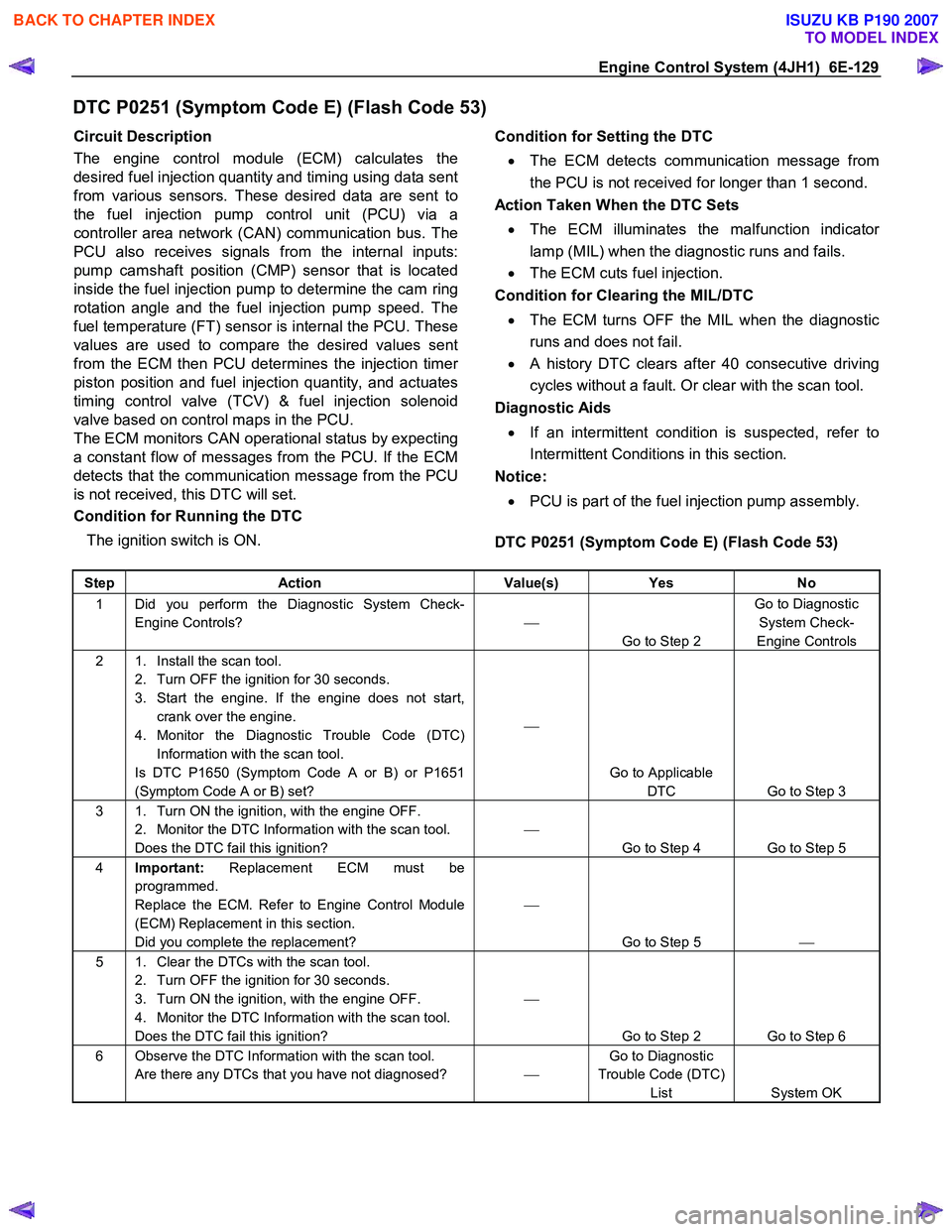
DTC P0251 (Symptom Code E) (Flash Code 53)
Circuit Description
The engine control module (ECM) calculates the
desired fuel injection quantity and timing using data sent
from various sensors. These desired data are sent to
the fuel injection pump control unit (PCU) via a
controller area network (CAN) communication bus. The
PCU also receives signals from the internal inputs:
pump camshaft position (CMP) sensor that is located
inside the fuel injection pump to determine the cam ring
rotation angle and the fuel injection pump speed. The
fuel temperature (FT) sensor is internal the PCU. These
values are used to compare the desired values sent
from the ECM then PCU determines the injection time
r
piston position and fuel injection quantity, and actuates
timing control valve (TCV) & fuel injection solenoid
valve based on control maps in the PCU.
The ECM monitors CAN operational status by expecting
a constant flow of messages from the PCU. If the ECM
detects that the communication message from the PCU
is not received, this DTC will set.
Condition for Running the DTC
The ignition switch is ON.
Condition for Setting the DTC
• The ECM detects communication message from
the PCU is not received for longer than 1 second.
Action Taken When the DTC Sets
• The ECM illuminates the malfunction indicato
r
lamp (MIL) when the diagnostic runs and fails.
• The ECM cuts fuel injection.
Condition for Clearing the MIL/DTC
• The ECM turns OFF the MIL when the diagnostic
runs and does not fail.
• A history DTC clears after 40 consecutive driving
cycles without a fault. Or clear with the scan tool.
Diagnostic Aids
• If an intermittent condition is suspected, refer to
Intermittent Conditions in this section.
Notice:
• PCU is part of the fuel injection pump assembly.
DTC P0251 (Symptom Code E) (Flash Code 53)
Step Action Value(s) Yes No
1 Did you perform the Diagnostic System Check-
Engine Controls?
Go to Step 2 Go to Diagnostic
System Check-
Engine Controls
2 1. Install the scan tool. 2. Turn OFF the ignition for 30 seconds.
3. Start the engine. If the engine does not start, crank over the engine.
4. Monitor the Diagnostic Trouble Code (DTC) Information with the scan tool.
Is DTC P1650 (Symptom Code A or B) or P1651
(Symptom Code A or B) set?
Go to Applicable DTC Go to Step 3
3 1. Turn ON the ignition, with the engine OFF. 2. Monitor the DTC Information with the scan tool.
Does the DTC fail this ignition?
Go to Step 4 Go to Step 5
4 Important: Replacement ECM must be
programmed.
Replace the ECM. Refer to Engine Control Module
(ECM) Replacement in this section.
Did you complete the replacement?
Go to Step 5
5 1. Clear the DTCs with the scan tool.
2. Turn OFF the ignition for 30 seconds.
3. Turn ON the ignition, with the engine OFF.
4. Monitor the DTC Information with the scan tool.
Does the DTC fail this ignition?
Go to Step 2 Go to Step 6
6 Observe the DTC Information with the scan tool. Are there any DTCs that you have not diagnosed? Go to Diagnostic
Trouble Code (DTC) List System OK
BACK TO CHAPTER INDEX
TO MODEL INDEX
ISUZU KB P190 2007
Page 1164 of 6020
6E-130 Engine Control System (4JH1)
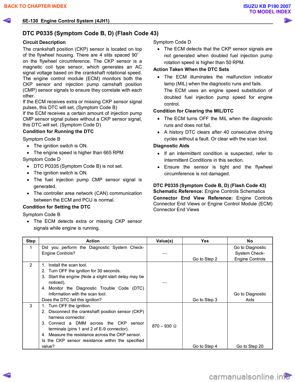
DTC P0335 (Symptom Code B, D) (Flash Code 43)
Circuit Description
The crankshaft position (CKP) sensor is located on top
of the flywheel housing. There are 4 slits spaced 90 °
on the flywheel circumference. The CKP sensor is a
magnetic coil type sensor, which generates an AC
signal voltage based on the crankshaft rotational speed.
The engine control module (ECM) monitors both the
CKP sensor and injection pump camshaft position
(CMP) sensor signals to ensure they correlate with each
other.
If the ECM receives extra or missing CKP sensor signal
pulses, this DTC will set. (Symptom Code B)
If the ECM receives a certain amount of injection pump
CMP sensor signal pulses without a CKP sensor signal,
this DTC will set. (Symptom Code D)
Condition for Running the DTC
Symptom Code B • The ignition switch is ON.
• The engine speed is higher than 665 RPM
Symptom Code D • DTC P0335 (Symptom Code B) is not set.
• The ignition switch is ON.
• The fuel injection pump CMP sensor signal is
generated.
• The controller area network (CAN) communication
between the ECM and PCU is normal.
Condition for Setting the DTC
Symptom Code B • The ECM detects extra or missing CKP senso
r
signals while engine is running.
Symptom Code D
• The ECM detects that the CKP sensor signals are
not generated when doubled fuel injection pump
rotation speed is higher than 50 RPM.
Action Taken When the DTC Sets
• The ECM illuminates the malfunction indicato
r
lamp (MIL) when the diagnostic runs and fails.
The ECM uses an engine speed substitution o
f
doubled fuel injection pump speed for engine
control.
Condition for Clearing the MIL/DTC
• The ECM turns OFF the MIL when the diagnostic
runs and does not fail.
• A history DTC clears after 40 consecutive driving
cycles without a fault. Or clear with the scan tool.
Diagnostic Aids
• If an intermittent condition is suspected, refer to
Intermittent Conditions in this section.
• Ensure the sensor is tight and the flywheel
circumference is not damaged.
DTC P0335 (Symptom Code B, D) (Flash Code 43)
Schematic Reference: Engine Controls Schematics
Connector End View Reference: Engine Controls
Connector End Views or Engine Control Module (ECM)
Connector End Views
Step Action Value(s) Yes No
1 Did you perform the Diagnostic System Check-
Engine Controls?
Go to Step 2 Go to Diagnostic
System Check-
Engine Controls
2 1. Install the scan tool. 2. Turn OFF the ignition for 30 seconds.
3. Start the engine (Note a slight start delay may be noticed).
4. Monitor the Diagnostic Trouble Code (DTC) Information with the scan tool.
Does the DTC fail this ignition?
Go to Step 3 Go to Diagnostic
Aids
3 1. Turn OFF the ignition. 2. Disconnect the crankshaft position sensor (CKP) harness connector.
3. Connect a DMM across the CKP sensor terminals (pins 1 and 2 of E-9 connector).
4. Measure the resistance across the CKP sensor.
Is the CKP sensor resistance within the specified
value? 870 – 930
Ω
Go to Step 4 Go to Step 20
BACK TO CHAPTER INDEX
TO MODEL INDEX
ISUZU KB P190 2007
Page 1167 of 6020
Engine Control System (4JH1) 6E-133
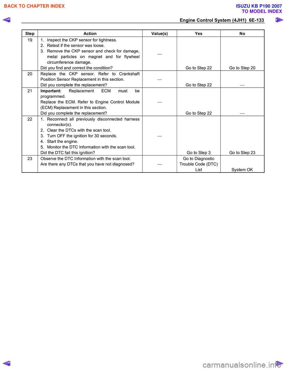
Step Action Value(s) Yes No
19 1. Inspect the CKP sensor for tightness.
2. Retest if the sensor was loose.
3. Remove the CKP sensor and check for damage, metal particles on magnet and for flywheel
circumference damage.
Did you find and correct the condition?
Go to Step 22 Go to Step 20
20 Replace the CKP sensor. Refer to Crankshaft Position Sensor Replacement in this section.
Did you complete the replacement?
Go to Step 22
21 Important: Replacement ECM must be
programmed.
Replace the ECM. Refer to Engine Control Module
(ECM) Replacement in this section.
Did you complete the replacement?
Go to Step 22
22 1. Reconnect all previously disconnected harness
connector(s).
2. Clear the DTCs with the scan tool.
3. Turn OFF the ignition for 30 seconds.
4. Start the engine.
5. Monitor the DTC Information with the scan tool.
Did the DTC fail this ignition?
Go to Step 3 Go to Step 23
23 Observe the DTC Information with the scan tool. Are there any DTCs that you have not diagnosed? Go to Diagnostic
Trouble Code (DTC) List System OK
BACK TO CHAPTER INDEX
TO MODEL INDEX
ISUZU KB P190 2007
Page 1168 of 6020
6E-134 Engine Control System (4JH1)
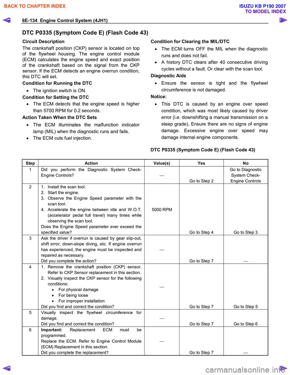
DTC P0335 (Symptom Code E) (Flash Code 43)
Circuit Description
The crankshaft position (CKP) sensor is located on top
of the flywheel housing. The engine control module
(ECM) calculates the engine speed and exact position
of the crankshaft based on the signal from the CKP
sensor. If the ECM detects an engine overrun condition,
this DTC will set.
Condition for Running the DTC
• The ignition switch is ON.
Condition for Setting the DTC • The ECM detects that the engine speed is highe
r
than 5700 RPM for 0.2 seconds.
Action Taken When the DTC Sets
• The ECM illuminates the malfunction indicato
r
lamp (MIL) when the diagnostic runs and fails.
• The ECM cuts fuel injection.
Condition for Clearing the MIL/DTC
• The ECM turns OFF the MIL when the diagnostic
runs and does not fail.
• A history DTC clears after 40 consecutive driving
cycles without a fault. Or clear with the scan tool.
Diagnostic Aids
• Ensure the sensor is tight and the flywheel
circumference is not damaged.
Notice:
• This DTC is caused by an engine over speed
condition, which was most likely caused by drive
r
error (i.e. downshifting a manual transmission on a
steep grade). Ensure there are no signs of engine
damage. Excessive engine over speed ma
y
damage internal engine components.
DTC P0335 (Symptom Code E) (Flash Code 43)
Step Action Value(s) Yes No
1 Did you perform the Diagnostic System Check-
Engine Controls?
Go to Step 2 Go to Diagnostic
System Check-
Engine Controls
2 1. Install the scan tool. 2. Start the engine.
3. Observe the Engine Speed parameter with the scan tool.
4. Accelerate the engine between idle and W .O.T. (accelerator pedal full travel) many times while
observing the scan tool.
Does the Engine Speed parameter ever exceed the
specified value? 5000 RPM
Go to Step 4 Go to Step 3
3 Ask the driver if overrun is caused by gear slip-out, shift error, down-slope diving, etc. If engine overrun
has experienced, the engine must be inspected and
repaired as necessary.
Did you complete the action?
Go to Step 7
4 1. Remove the crankshaft position (CKP) sensor.
Refer to CKP Sensor replacement in this section.
2. Visually inspect the CKP sensor for the following conditions: • For physical damage
• For being loose
• For improper installation
Did you find and correct the condition?
Go to Step 7 Go to Step 5
5 Visually inspect the flywheel circumference for damage.
Did you find and correct the condition?
Go to Step 7 Go to Step 6
6 Important: Replacement ECM must be
programmed.
Replace the ECM. Refer to Engine Control Module
(ECM) Replacement in this section.
Did you complete the replacement?
Go to Step 7
BACK TO CHAPTER INDEX
TO MODEL INDEX
ISUZU KB P190 2007
Page 1170 of 6020
6E-136 Engine Control System (4JH1)
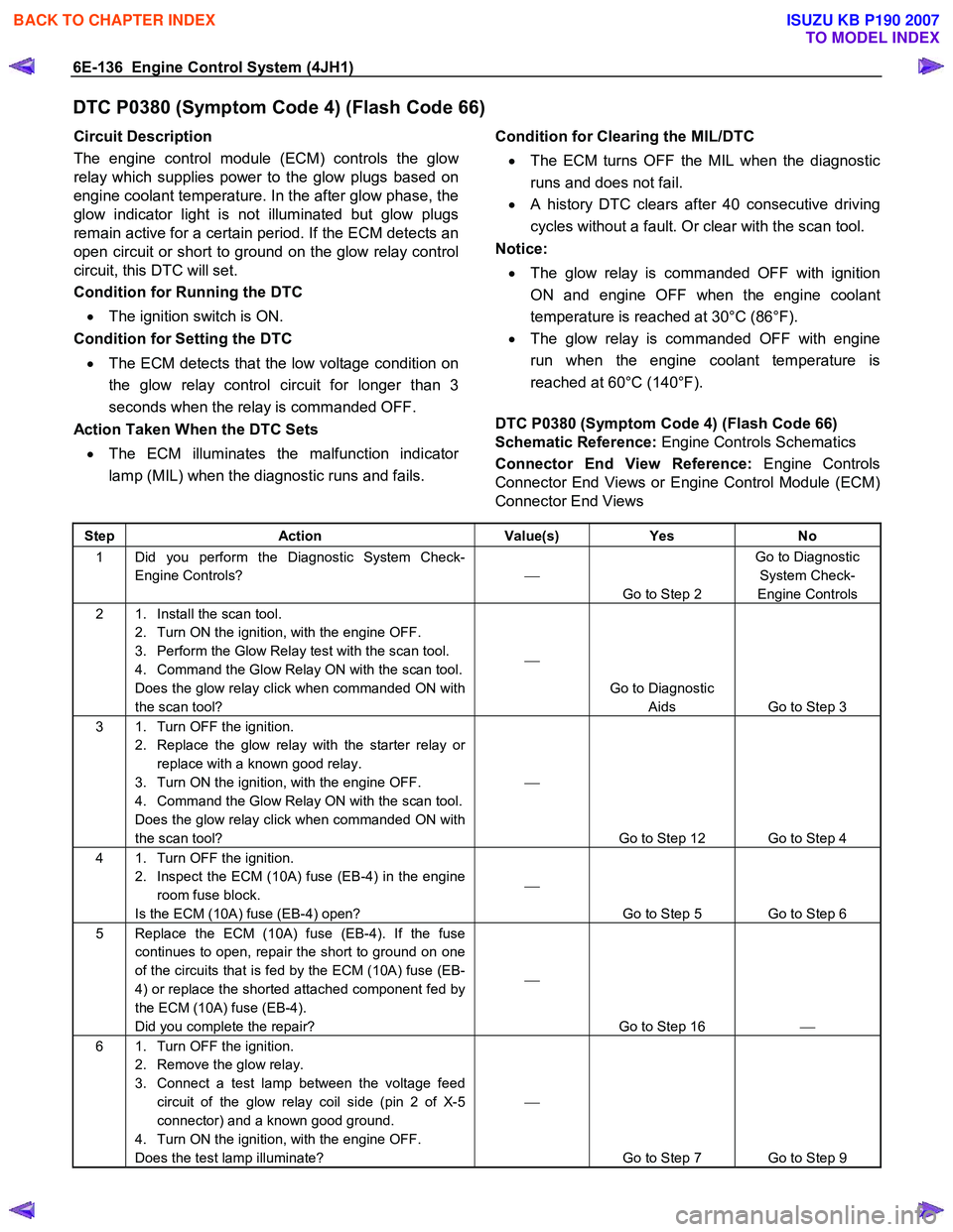
DTC P0380 (Symptom Code 4) (Flash Code 66)
Circuit Description
The engine control module (ECM) controls the glo
w
relay which supplies power to the glow plugs based on
engine coolant temperature. In the after glow phase, the
glow indicator light is not illuminated but glow plugs
remain active for a certain period. If the ECM detects an
open circuit or short to ground on the glow relay control
circuit, this DTC will set.
Condition for Running the DTC
• The ignition switch is ON.
Condition for Setting the DTC
• The ECM detects that the low voltage condition on
the glow relay control circuit for longer than 3
seconds when the relay is commanded OFF.
Action Taken When the DTC Sets
• The ECM illuminates the malfunction indicato
r
lamp (MIL) when the diagnostic runs and fails.
Condition for Clearing the MIL/DTC
• The ECM turns OFF the MIL when the diagnostic
runs and does not fail.
• A history DTC clears after 40 consecutive driving
cycles without a fault. Or clear with the scan tool.
Notice:
• The glow relay is commanded OFF with ignition
ON and engine OFF when the engine coolant
temperature is reached at 30°C (86°F).
• The glow relay is commanded OFF with engine
run when the engine coolant temperature is
reached at 60°C (140°F).
DTC P0380 (Symptom Code 4) (Flash Code 66)
Schematic Reference: Engine Controls Schematics
Connector End View Reference: Engine Controls
Connector End Views or Engine Control Module (ECM)
Connector End Views
Step Action Value(s) Yes No
1 Did you perform the Diagnostic System Check-
Engine Controls?
Go to Step 2 Go to Diagnostic
System Check-
Engine Controls
2 1. Install the scan tool. 2. Turn ON the ignition, with the engine OFF.
3. Perform the Glow Relay test with the scan tool.
4. Command the Glow Relay ON with the scan tool.
Does the glow relay click when commanded ON with
the scan tool?
Go to Diagnostic Aids Go to Step 3
3 1. Turn OFF the ignition. 2. Replace the glow relay with the starter relay or replace with a known good relay.
3. Turn ON the ignition, with the engine OFF.
4. Command the Glow Relay ON with the scan tool.
Does the glow relay click when commanded ON with
the scan tool?
Go to Step 12 Go to Step 4
4 1. Turn OFF the ignition. 2. Inspect the ECM (10A) fuse (EB-4) in the engine room fuse block.
Is the ECM (10A) fuse (EB-4) open?
Go to Step 5 Go to Step 6
5 Replace the ECM (10A) fuse (EB-4). If the fuse continues to open, repair the short to ground on one
of the circuits that is fed by the ECM (10A) fuse (EB-
4) or replace the shorted attached component fed by
the ECM (10A) fuse (EB-4).
Did you complete the repair?
Go to Step 16
6 1. Turn OFF the ignition.
2. Remove the glow relay.
3. Connect a test lamp between the voltage feed circuit of the glow relay coil side (pin 2 of X-5
connector) and a known good ground.
4. Turn ON the ignition, with the engine OFF.
Does the test lamp illuminate?
Go to Step 7 Go to Step 9
BACK TO CHAPTER INDEX
TO MODEL INDEX
ISUZU KB P190 2007