2007 ISUZU KB P190 oil
[x] Cancel search: oilPage 5736 of 6020

9A1-54 RESTRAINT CONTROL SYSTEM
DTC B0042 (Flash Code 42) Driver Pretensioner Squib Circuit High
Resistance
RTW 79ALF000301
Circuit Description
W hen the ignition switch is turned “ON”, the SRS
control unit will perform tests to diagnose critical
malfunctions within itself. Upon passing these tests,
“Ignition 1”, and deployment loop voltages are
measured to ensure they are within their respective
normal voltage ranges.
The SRS control unit then proceeds with the
“Resistance Measurement Test” “Driver Pretensioner
Low” terminal “7” is grounded through a current sink
and the driver current source connected to “Drive
r
Pretensioner High” terminal “8” allows a known amount
of current to flow. By monitoring the voltage difference
between “Driver Pretensioner High” and “Drive
r
Pretensioner Low”, the SRS control unit calculates the
combined resistance of the driver pretensione
r
assembly, SRS coil assembly, harness wiring circuits
“Driver Pretensioner High” and “Driver Pretensione
r
Low” and connector terminal contact.
BACK TO CHAPTER INDEX TO MODEL INDEX
ISUZU KB P190 2007
Page 5737 of 6020
RESTRAINT CONTROL SYSTEM 9A1-55
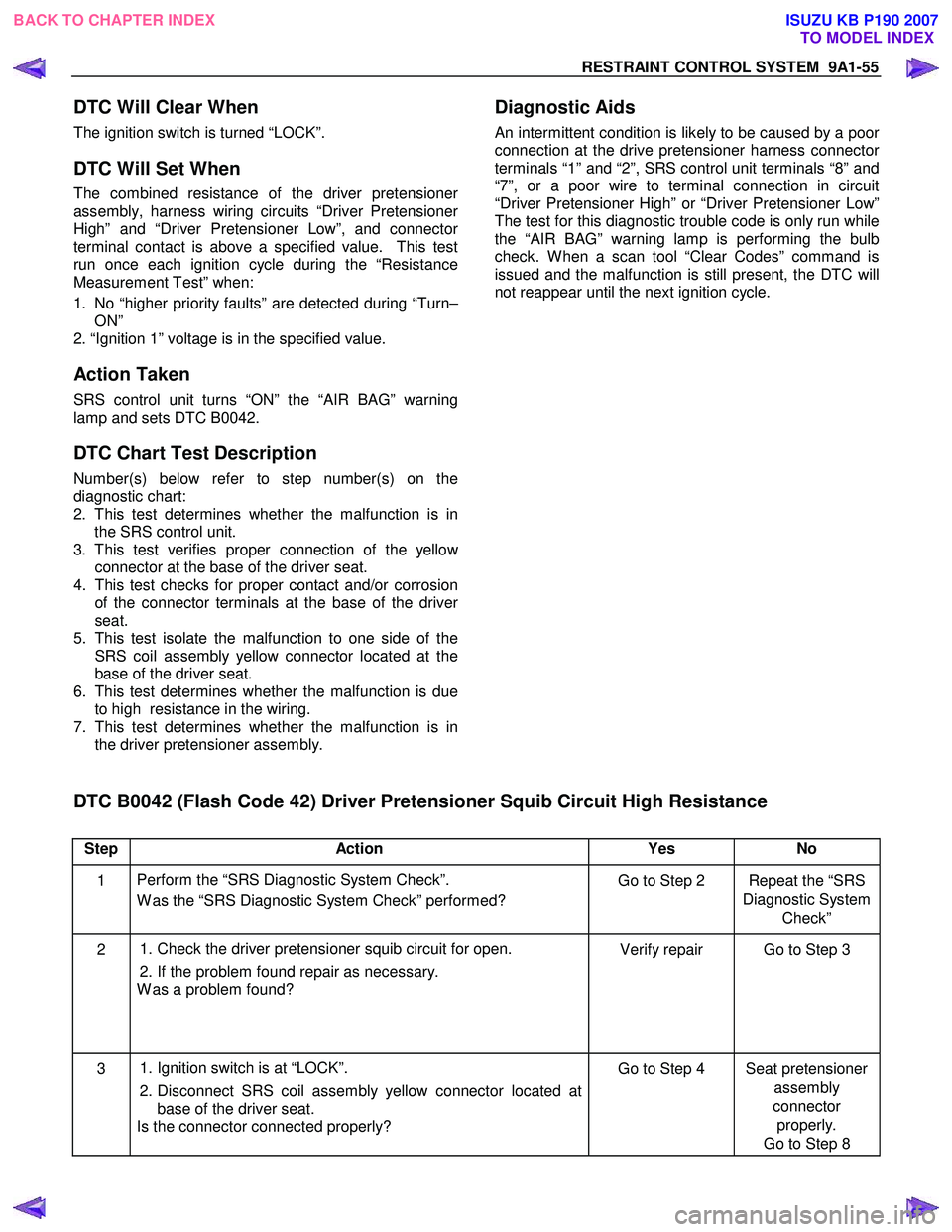
DTC Will Clear When
The ignition switch is turned “LOCK”.
DTC Will Set When
The combined resistance of the driver pretensioner
assembly, harness wiring circuits “Driver Pretensioner
High” and “Driver Pretensioner Low”, and connector
terminal contact is above a specified value. This test
run once each ignition cycle during the “Resistance
Measurement Test” when:
1. No “higher priority faults” are detected during “Turn–
ON”
2. “Ignition 1” voltage is in the specified value.
Action Taken
SRS control unit turns “ON” the “AIR BAG” warning
lamp and sets DTC B0042.
DTC Chart Test Description
Number(s) below refer to step number(s) on the
diagnostic chart:
2. This test determines whether the malfunction is in
the SRS control unit.
3. This test verifies proper connection of the yello
w
connector at the base of the driver seat.
4. This test checks for proper contact and/or corrosion
of the connector terminals at the base of the drive
r
seat.
5. This test isolate the malfunction to one side of the
SRS coil assembly yellow connector located at the
base of the driver seat.
6. This test determines whether the malfunction is due
to high resistance in the wiring.
7. This test determines whether the malfunction is in
the driver pretensioner assembly.
Diagnostic Aids
An intermittent condition is likely to be caused by a poor
connection at the drive pretensioner harness connecto
r
terminals “1” and “2”, SRS control unit terminals “8” and
“7”, or a poor wire to terminal connection in circuit
“Driver Pretensioner High” or “Driver Pretensioner Low”
The test for this diagnostic trouble code is only run while
the “AIR BAG” warning lamp is performing the bulb
check. W hen a scan tool “Clear Codes” command is
issued and the malfunction is still present, the DTC will
not reappear until the next ignition cycle.
DTC B0042 (Flash Code 42) Driver Pretensioner Squib Circuit High Resistance
Step Action Yes No
1 Perform the “SRS Diagnostic System Check”.
W as the “SRS Diagnostic System Check” performed? Go to Step 2 Repeat the “SRS
Diagnostic System Check”
2
1. Check the driver pretensioner squib circuit for open.
2. If the problem found repair as necessary.
W as a problem found? Verify repair Go to Step 3
3
1. Ignition switch is at “LOCK”.
2. Disconnect SRS coil assembly yellow connector located at
base of the driver seat.
Is the connector connected properly? Go to Step 4 Seat pretensioner
assembly
connector properly.
Go to Step 8
BACK TO CHAPTER INDEX TO MODEL INDEX
ISUZU KB P190 2007
Page 5872 of 6020
IMMOBILIZER CONTROL SYSTEM (4JK1/4JJ1/HFV6) 11A-21
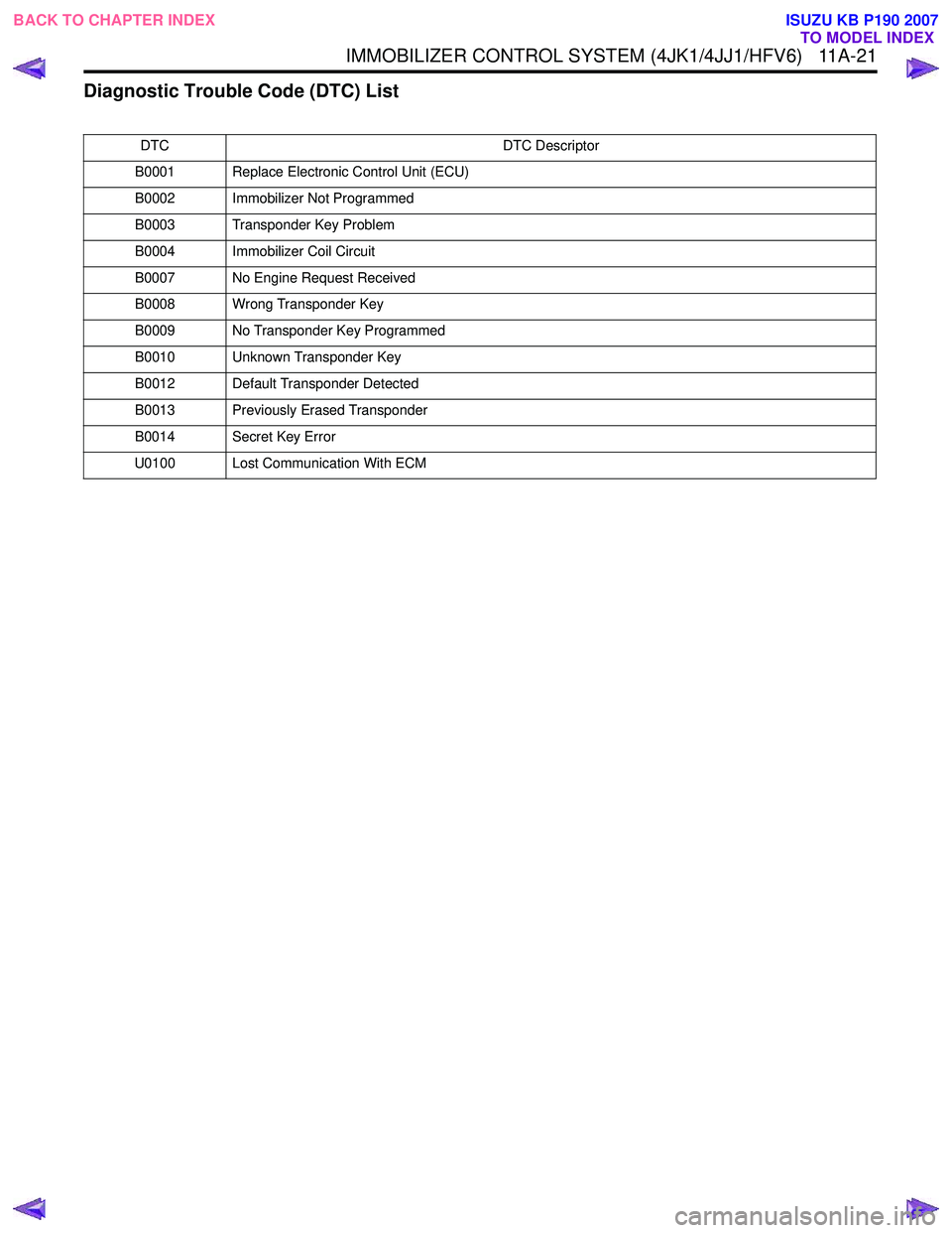
Diagnostic Trouble Code (DTC) List
DTCDTC Descriptor
B0001 Replace Electronic Control Unit (ECU)
B0002 Immobilizer Not Programmed
B0003 Transponder Key Problem
B0004 Immobilizer Coil Circuit
B0007 No Engine Request Received
B0008 Wrong Transponder Key
B0009 No Transponder Key Programmed
B0010 Unknown Transponder Key
B0012 Default Transponder Detected
B0013 Previously Erased Transponder
B0014 Secret Key Error
U0100 Lost Communication With ECM
BACK TO CHAPTER INDEX TO MODEL INDEX
ISUZU KB P190 2007
Page 5875 of 6020
11A-24 IMMOBILIZER CONTROL SYSTEM (4JK1/4JJ1/HFV6)
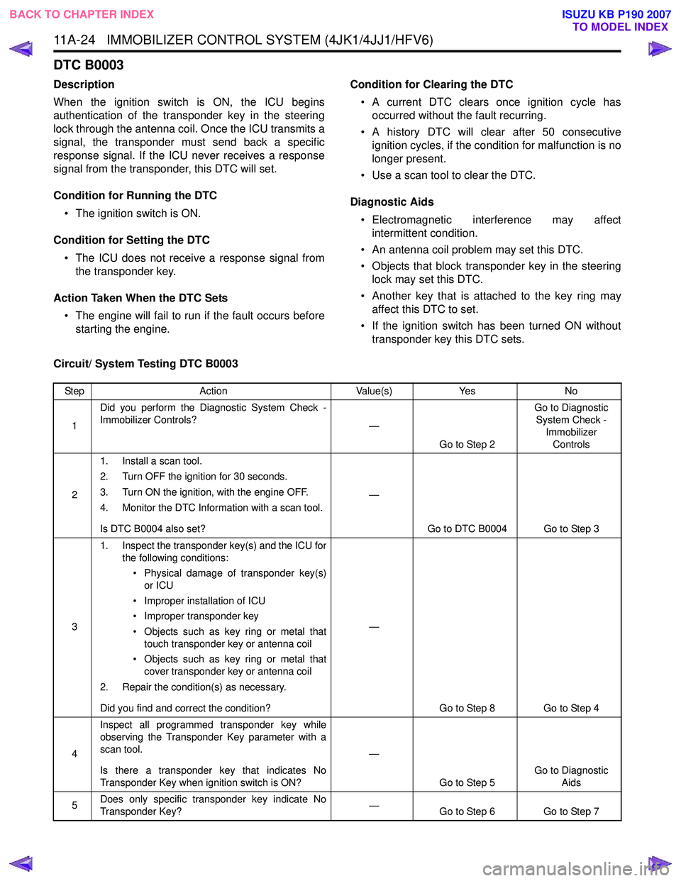
DTC B0003
Description
When the ignition switch is ON, the ICU begins
authentication of the transponder key in the steering
lock through the antenna coil. Once the ICU transmits a
signal, the transponder must send back a specific
response signal. If the ICU never receives a response
signal from the transponder, this DTC will set.
Condition for Running the DTC • The ignition switch is ON.
Condition for Setting the DTC • The ICU does not receive a response signal from the transponder key.
Action Taken When the DTC Sets • The engine will fail to run if the fault occurs before starting the engine. Condition for Clearing the DTC
• A current DTC clears once ignition cycle has occurred without the fault recurring.
• A history DTC will clear after 50 consecutive ignition cycles, if the condition for malfunction is no
longer present.
• Use a scan tool to clear the DTC.
Diagnostic Aids • Electromagnetic interference may affect intermittent condition.
• An antenna coil problem may set this DTC.
• Objects that block transponder key in the steering lock may set this DTC.
• Another key that is attached to the key ring may affect this DTC to set.
• If the ignition switch has been turned ON without transponder key this DTC sets.
Circuit/ System Testing DTC B0003
Step Action Value(s)Yes No
1 Did you perform the Diagnostic System Check -
Immobilizer Controls? —
Go to Step 2 Go to Diagnostic
System Check -
Immobilizer Controls
2 1. Install a scan tool.
2. Turn OFF the ignition for 30 seconds.
3. Turn ON the ignition, with the engine OFF.
4. Monitor the DTC Information with a scan tool.
Is DTC B0004 also set? —
Go to DTC B0004 Go to Step 3
3 1. Inspect the transponder key(s) and the ICU for
the following conditions:
• Physical damage of transponder key(s) or ICU
• Improper installation of ICU
• Improper transponder key
• Objects such as key ring or metal that touch transponder key or antenna coil
• Objects such as key ring or metal that cover transponder key or antenna coil
2. Repair the condition(s) as necessary.
Did you find and correct the condition? —
Go to Step 8 Go to Step 4
4 Inspect all programmed transponder key while
observing the Transponder Key parameter with a
scan tool.
Is there a transponder key that indicates No
Transponder Key when ignition switch is ON? —
Go to Step 5 Go to Diagnostic
Aids
5 Does only specific transponder key indicate No
Transponder Key? —
Go to Step 6 Go to Step 7
BACK TO CHAPTER INDEX
TO MODEL INDEX
ISUZU KB P190 2007
Page 5877 of 6020
11A-26 IMMOBILIZER CONTROL SYSTEM (4JK1/4JJ1/HFV6)
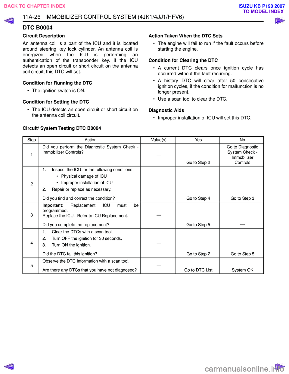
DTC B0004
Circuit Description
An antenna coil is a part of the ICU and it is located
around steering key lock cylinder. An antenna coil is
energized when the ICU is performing an
authentication of the transponder key. If the ICU
detects an open circuit or short circuit on the antenna
coil circuit, this DTC will set.
Condition for Running the DTC • The ignition switch is ON.
Condition for Setting the DTC • The ICU detects an open circuit or short circuit on the antenna coil circuit. Action Taken When the DTC Sets
• The engine will fail to run if the fault occurs before starting the engine.
Condition for Clearing the DTC • A current DTC clears once ignition cycle has occurred without the fault recurring.
• A history DTC will clear after 50 consecutive ignition cycles, if the condition for malfunction is no
longer present.
• Use a scan tool to clear the DTC.
Diagnostic Aids • Improper installation of ICU will set this DTC.
Circuit/ System Testing DTC B0004
Step Action Value(s)Yes No
1 Did you perform the Diagnostic System Check -
Immobilizer Controls? —
Go to Step 2 Go to Diagnostic
System Check - Immobilizer Controls
2 1. Inspect the ICU for the following conditions:
• Physical damage of ICU
• Improper installation of ICU
2. Repair or replace as necessary.
Did you find and correct the condition? —
Go to Step 4 Go to Step 3
3 Important
: Replacement ICU must be
programmed.
Replace the ICU. Refer to ICU Replacement.
Did you complete the replacement? —
Go to Step 5
—
41. Clear the DTCs with a scan tool.
2. Turn OFF the ignition for 30 seconds.
3. Turn ON the ignition.
Did the DTC fail this ignition? —
Go to Step 2 Go to Step 5
5 Observe the DTC Information with a scan tool.
Are there any DTCs that you have not diagnosed? —
Go to DTC List System OK
BACK TO CHAPTER INDEX
TO MODEL INDEX
ISUZU KB P190 2007
Page 5879 of 6020
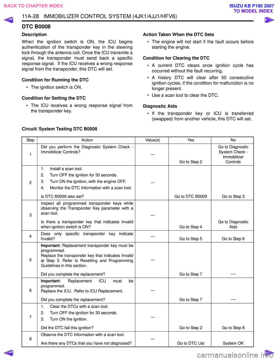
11A-28 IMMOBILIZER CONTROL SYSTEM (4JK1/4JJ1/HFV6)
DTC B0008
Description
When the ignition switch is ON, the ICU begins
authentication of the transponder key in the steering
lock through the antenna coil. Once the ICU transmits a
signal, the transponder must send back a specific
response signal. If the ICU receives a wrong response
signal from the transponder, this DTC will set.
Condition for Running the DTC • The ignition switch is ON.
Condition for Setting the DTC • The ICU receives a wrong response signal from the transponder key. Action Taken When the DTC Sets
• The engine will not start if the fault occurs before starting the engine.
Condition for Clearing the DTC • A current DTC clears once ignition cycle has occurred without the fault recurring.
• A history DTC will clear after 50 consecutive ignition cycles, if the condition for malfunction is no
longer present.
• Use a scan tool to clear the DTC.
Diagnostic Aids • If the transponder key or ICU is transferred (swapped) from another vehicle, this DTC will set.
Circuit/ System Testing DTC B0008
Step Action Value(s)Yes No
1 Did you perform the Diagnostic System Check -
Immobilizer Controls? —
Go to Step 2 Go to Diagnostic
System Check - Immobilizer Controls
2 1. Install a scan tool.
2. Turn OFF the ignition for 30 seconds.
3. Turn ON the ignition, with the engine OFF.
4. Monitor the DTC Information with a scan tool.
Is DTC B0009 also set? —
Go to DTC B0009 Go to Step 3
3 Inspect all programmed transponder keys while
observing the Transponder Key parameter with a
scan tool.
Is there a transponder key that indicates Invalid
when ignition switch is ON? —
Go to Step 4 Go to Diagnostic
Aids
4 Does only specific transponder key indicate
Invalid? —
Go to Step 5 Go to Step 6
5 Important
: Replacement transponder key must be
programmed.
Replace the transponder key that indicates Invalid
at Step 3. Refer to Resetting and Programming
Guidelines in this section.
Did you complete the replacement? —
Go to Step 7
—
6Important
: Replacement ICU must be
programmed.
Replace the ICU. Refer to ICU Replacement.
Did you complete the replacement? —
Go to Step 7
—
71. Clear the DTCs with a scan tool.
2. Turn OFF the ignition for 30 seconds.
3. Turn ON the ignition.
Did the DTC fail this ignition? —
Go to Step 2 Go to Step 8
8 Observe the DTC Information with a scan tool.
Are there any DTCs that you have not diagnosed? —
Go to DTC List System OK
BACK TO CHAPTER INDEX
TO MODEL INDEX
ISUZU KB P190 2007
Page 5881 of 6020
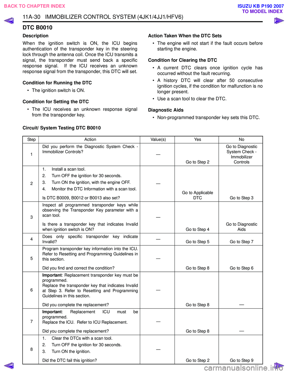
11A-30 IMMOBILIZER CONTROL SYSTEM (4JK1/4JJ1/HFV6)
DTC B0010
Description
When the ignition switch is ON, the ICU begins
authentication of the transponder key in the steering
lock through the antenna coil. Once the ICU transmits a
signal, the transponder must send back a specific
response signal. If the ICU receives an unknown
response signal from the transponder, this DTC will set.
Condition for Running the DTC • The ignition switch is ON.
Condition for Setting the DTC • The ICU receives an unknown response signal from the transponder key. Action Taken When the DTC Sets
• The engine will not start if the fault occurs before starting the engine.
Condition for Clearing the DTC • A current DTC clears once ignition cycle has occurred without the fault recurring.
• A history DTC will clear after 50 consecutive ignition cycles, if the condition for malfunction is no
longer present.
• Use a scan tool to clear the DTC.
Diagnostic Aids • Non-programmed transponder key sets this DTC.
Circuit/ System Testing DTC B0010
Step Action Value(s)Yes No
1 Did you perform the Diagnostic System Check -
Immobilizer Controls? —
Go to Step 2 Go to Diagnostic
System Check - Immobilizer Controls
2 1. Install a scan tool.
2. Turn OFF the ignition for 30 seconds.
3. Turn ON the ignition, with the engine OFF.
4. Monitor the DTC Information with a scan tool.
Is DTC B0009, B0012 or B0013 also set? —
Go to Applicable DTC Go to Step 3
3 Inspect all programmed transponder keys while
observing the Transponder Key parameter with a
scan tool.
Is there a transponder key that indicates Invalid
when ignition switch is ON? —
Go to Step 4 Go to Diagnostic
Aids
4 Does only specific transponder key indicate
Invalid? —
Go to Step 5 Go to Step 7
5 Program transponder key information into the ICU.
Refer to Resetting and Programming Guidelines in
this section.
Did you find and correct the condition? —
Go to Step 8 Go to Step 6
6 Important
: Replacement transponder key must be
programmed.
Replace the transponder key that indicates Invalid
at Step 3. Refer to Resetting and Programming
Guidelines in this section.
Did you complete the replacement? —
Go to Step 8
—
7Important
: Replacement ICU must be
programmed.
Replace the ICU. Refer to ICU Replacement.
Did you complete the replacement? —
Go to Step 8
—
81. Clear the DTCs with a scan tool.
2. Turn OFF the ignition for 30 seconds.
3. Turn ON the ignition.
Did the DTC fail this ignition? —
Go to Step 2 Go to Step 9
BACK TO CHAPTER INDEX TO MODEL INDEX
ISUZU KB P190 2007
Page 5884 of 6020
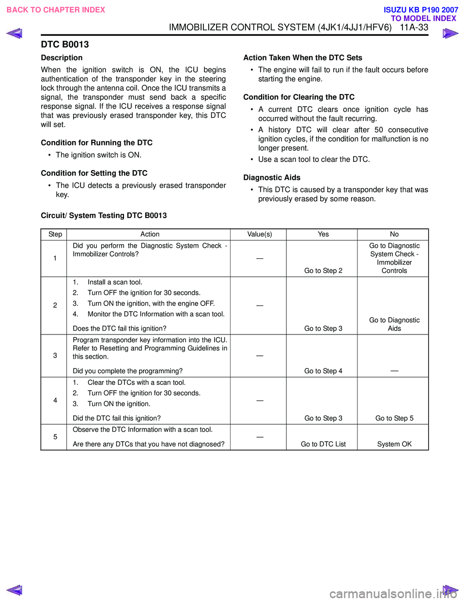
IMMOBILIZER CONTROL SYSTEM (4JK1/4JJ1/HFV6) 11A-33
DTC B0013
Description
When the ignition switch is ON, the ICU begins
authentication of the transponder key in the steering
lock through the antenna coil. Once the ICU transmits a
signal, the transponder must send back a specific
response signal. If the ICU receives a response signal
that was previously erased transponder key, this DTC
will set.
Condition for Running the DTC • The ignition switch is ON.
Condition for Setting the DTC • The ICU detects a previously erased transponder key. Action Taken When the DTC Sets
• The engine will fail to run if the fault occurs before starting the engine.
Condition for Clearing the DTC • A current DTC clears once ignition cycle has occurred without the fault recurring.
• A history DTC will clear after 50 consecutive ignition cycles, if the condition for malfunction is no
longer present.
• Use a scan tool to clear the DTC.
Diagnostic Aids • This DTC is caused by a transponder key that was previously erased by some reason.
Circuit/ System Testing DTC B0013
Step Action Value(s)Yes No
1 Did you perform the Diagnostic System Check -
Immobilizer Controls? —
Go to Step 2 Go to Diagnostic
System Check - Immobilizer Controls
2 1. Install a scan tool.
2. Turn OFF the ignition for 30 seconds.
3. Turn ON the ignition, with the engine OFF.
4. Monitor the DTC Information with a scan tool.
Does the DTC fail this ignition? —
Go to Step 3 Go to Diagnostic
Aids
3 Program transponder key information into the ICU.
Refer to Resetting and Programming Guidelines in
this section.
Did you complete the programming? —
Go to Step 4
—
41. Clear the DTCs with a scan tool.
2. Turn OFF the ignition for 30 seconds.
3. Turn ON the ignition.
Did the DTC fail this ignition? —
Go to Step 3 Go to Step 5
5 Observe the DTC Information with a scan tool.
Are there any DTCs that you have not diagnosed? —
Go to DTC List System OK
BACK TO CHAPTER INDEX
TO MODEL INDEX
ISUZU KB P190 2007