Page 4881 of 6020
TRANSFER CONTROL SYSTEM 7D1-7
7B4-PDF3
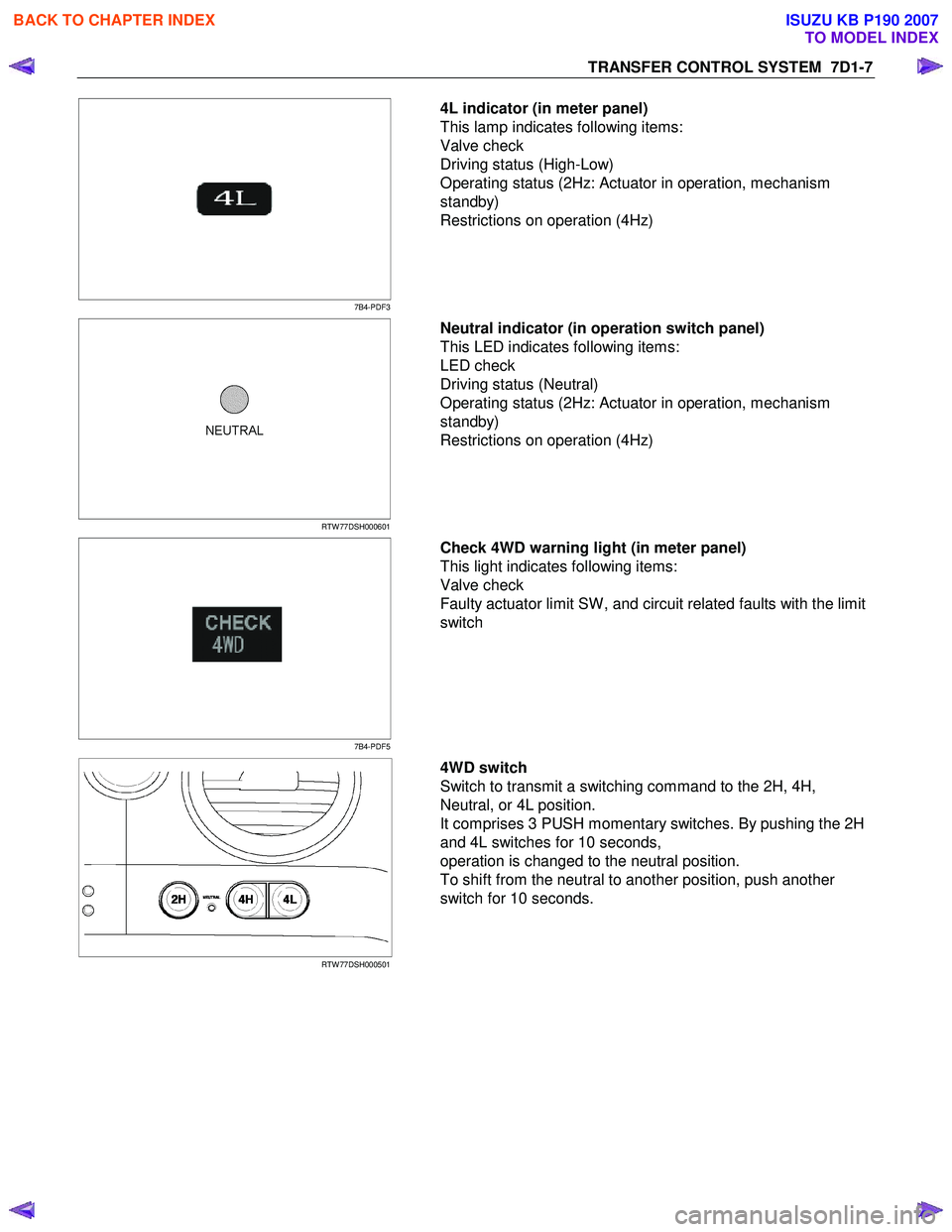
4L indicator (in meter panel)
This lamp indicates following items:
Valve check
Driving status (High-Low)
Operating status (2Hz: Actuator in operation, mechanism
standby)
Restrictions on operation (4Hz)
RTW 77DSH000601
Neutral indicator (in operation switch panel)
This LED indicates following items:
LED check
Driving status (Neutral)
Operating status (2Hz: Actuator in operation, mechanism
standby)
Restrictions on operation (4Hz)
7B4-PDF5
Check 4WD warning light (in meter panel)
This light indicates following items:
Valve check
Faulty actuator limit SW , and circuit related faults with the limit
switch
RTW 77DSH000501
4WD switch
Switch to transmit a switching command to the 2H, 4H,
Neutral, or 4L position.
It comprises 3 PUSH momentary switches. By pushing the 2H
and 4L switches for 10 seconds,
operation is changed to the neutral position.
To shift from the neutral to another position, push another
switch for 10 seconds.
BACK TO CHAPTER INDEX
TO MODEL INDEX
ISUZU KB P190 2007
Page 4907 of 6020
TRANSFER CONTROL SYSTEM 7D1-33
CIRCUIT DIAGRAM
C24SE
RTW 680XF014201
BACK TO CHAPTER INDEX
TO MODEL INDEX
ISUZU KB P190 2007
Page 4925 of 6020
TRANSFER CONTROL SYSTEM 7D1-51
Trouble diagnosis based on the operation switch, transfer indicator lamp and operating
sound “Check 4WD” indicator ON (operation guard based on the transfer actuator
position detection error)
This condition indicates a faulty circuit related with the detection (limit) switches of the system actuator.
Detection (limit) switches detect the actuator operating angle based on their combinations.
The controller monitors transition of the actuator based on the combination of the detection (limit) switch output.
If the transition based on the combinations indicates some trouble, it is memorized, and shifting operation is
stopped when the trouble is counted 5 times, and the “Check 4W D” indicator lights up. At this time, the system
permits operation to 2H only.
W hen such a condition occurs, inspection of the transfer shift actuator, checking of the harness related with the
detection (limit) switch, and erasure of the memory of the controller is required.
(Refer to the memory erasure procedure for the erasure of the memory.)
At this time, the position indicator may flash at 4Hz. It means that a detection (limit) switch trouble wad detected
in the operation process shown by that position indicator (example: 4W D indicator when shifting from 2H to 4H).
Caution:
During trouble diagnosis and correction, do not turn ON the ignition with the harness connector of the
transfer actuator disconnected. (Do not disconnect the harness connector of the transfer actuator when
the ignition is ON.)
If the controller is connected during this condition, a limit SW trouble is judged and the above-described
“Check 4WD” condition occurs.
This can be reset by clearing the memory.
When disconnecting the harness connector of the actuator and turning the ignition ON is required, remove
the controller at the same time or remove the IG power fuse of the transfer controller.
BACK TO CHAPTER INDEX
TO MODEL INDEX
ISUZU KB P190 2007
Page 4926 of 6020
7D1-52 TRANSFER CONTROL SYSTEM
Memory erasing procedure
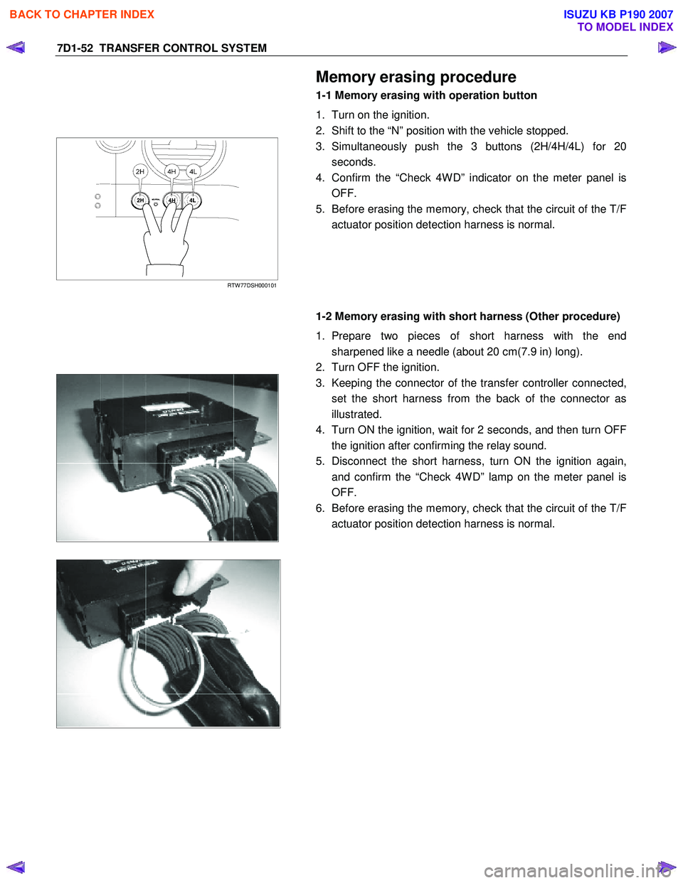
1-1 Memory erasing with operation button
1. Turn on the ignition.
2. Shift to the “N” position with the vehicle stopped.
RTW 77DSH000101
3. Simultaneously push the 3 buttons (2H/4H/4L) for 20
seconds.
4. Confirm the “Check 4W D” indicator on the meter panel is OFF.
5. Before erasing the memory, check that the circuit of the T/F actuator position detection harness is normal.
1-2 Memory erasing with short harness (Other procedure)
1. Prepare two pieces of short harness with the end sharpened like a needle (about 20 cm(7.9 in) long).
2. Turn OFF the ignition.
3. Keeping the connector of the transfer controller connected,
set the short harness from the back of the connector as
illustrated.
4. Turn ON the ignition, wait for 2 seconds, and then turn OFF the ignition after confirming the relay sound.
5. Disconnect the short harness, turn ON the ignition again, and confirm the “Check 4W D” lamp on the meter panel is
OFF.
6. Before erasing the memory, check that the circuit of the T/F actuator position detection harness is normal.
BACK TO CHAPTER INDEX
TO MODEL INDEX
ISUZU KB P190 2007
Page 4929 of 6020
TRANSFER CONTROL SYSTEM 7D1-55
Cannot shift from 2WD to 4H or 4L.
When shifting from 2H to other position, the indicator (4WD, 4Lo, Check4WD, neutral)
does not respond.
Step Action Yes No
1 Is the ignition switch ON? Go to step 2.
Turn the ignition switch ON and
trace this chart from the
beginning.
2 Does the transfer-related
indicators (4W D, 4Lo, Check
4W D, neutral) light up for 2
seconds when the ignition switch
is turned ON? Failed operation switch. Or,
Failed controller. Indicator lamp burnt out.
Disconnected harness wire.
After repairing, trace this chart
from the beginning.
Even after correction step 1-1(*), 4WD indicator blinks at 4Hz and changes to 2H after 10
seconds.
Step Action Yes No
1 Is the ignition switch ON? Go to step 2.
Turn the ignition switch ON and
trace this chart from the
beginning.
2 Does the transfer-related
indicators (4W D, 4Lo, Check
4W D, neutral) light up for 2
seconds when the ignition switch
is turned ON? Go to step 3.
Indicator lamp burnt out.
Disconnected harness wire.
After repairing, trace this chart
from the beginning.
3 After 2 seconds, check that the
Check4W D lamp is ON or OFF.
Is the Check4W D lamp OFF? Go to step 4.
Failed actuator position detection
switch (LS1, LS2, LS3, LS4,
GND).
Short or disconnection of harness
of this detection switch.
After repairing, trace this chart
from the beginning.
4 Press the 4H button.
Is sound of relay heard from the
transfer control? Go to step 5.
Failed controller.
Replace the controller and trace
this chart from the beginning.
5 Is the sound of a running motor
heard? Failed control system of the
transfer mechanism. Check and
repair and trace this chart from
the beginning. Failed actuator motor.
Disconnected controller motor
drive output circuit, GND short
circuit. +B fuse blown out.
Disconnection of that harness.
After repairing, trace this chart
from the beginning.
*Before determining a trouble (Non-trouble mode)
BACK TO CHAPTER INDEX
TO MODEL INDEX
ISUZU KB P190 2007
Page 4931 of 6020
TRANSFER CONTROL SYSTEM 7D1-57
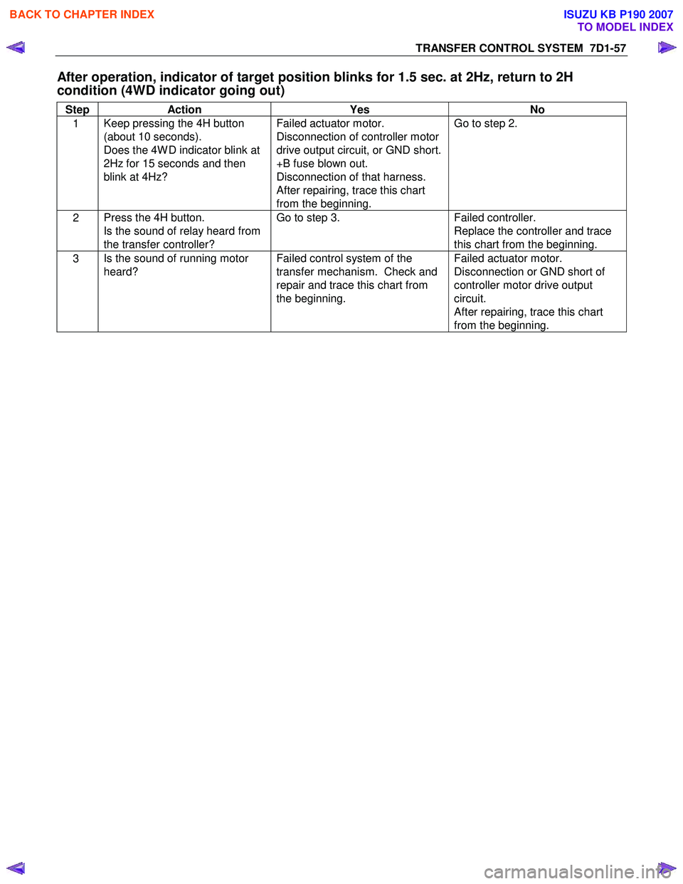
After operation, indicator of target position blinks for 1.5 sec. at 2Hz, return to 2H
condition (4WD indicator going out)
Step Action Yes No
1 Keep pressing the 4H button
(about 10 seconds).
Does the 4W D indicator blink at
2Hz for 15 seconds and then
blink at 4Hz? Failed actuator motor.
Disconnection of controller motor
drive output circuit, or GND short.
+B fuse blown out.
Disconnection of that harness.
After repairing, trace this chart
from the beginning. Go to step 2.
2
Press the 4H button.
Is the sound of relay heard from
the transfer controller? Go to step 3.
Failed controller.
Replace the controller and trace
this chart from the beginning.
3 Is the sound of running motor
heard? Failed control system of the
transfer mechanism. Check and
repair and trace this chart from
the beginning. Failed actuator motor.
Disconnection or GND short of
controller motor drive output
circuit.
After repairing, trace this chart
from the beginning.
BACK TO CHAPTER INDEX
TO MODEL INDEX
ISUZU KB P190 2007
Page 4932 of 6020
7D1-58 TRANSFER CONTROL SYSTEM
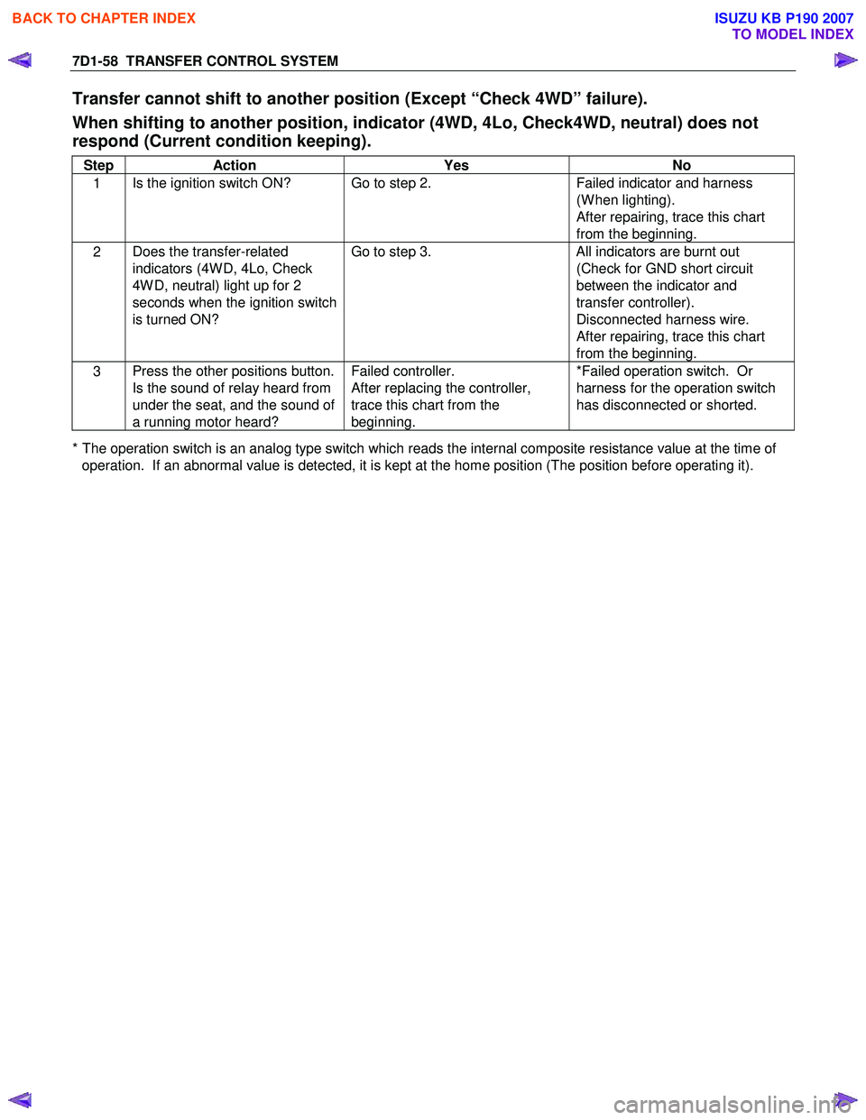
Transfer cannot shift to another position (Except “Check 4WD” failure).
When shifting to another position, indicator (4WD, 4Lo, Check4WD, neutral) does not
respond (Current condition keeping).
Step Action Yes No
1 Is the ignition switch ON? Go to step 2.
Failed indicator and harness
(W hen lighting).
After repairing, trace this chart
from the beginning.
2 Does the transfer-related
indicators (4W D, 4Lo, Check
4W D, neutral) light up for 2
seconds when the ignition switch
is turned ON? Go to step 3.
All indicators are burnt out
(Check for GND short circuit
between the indicator and
transfer controller).
Disconnected harness wire.
After repairing, trace this chart
from the beginning.
3 Press the other positions button.
Is the sound of relay heard from
under the seat, and the sound of
a running motor heard? Failed controller.
After replacing the controller,
trace this chart from the
beginning. *Failed operation switch. Or
harness for the operation switch
has disconnected or shorted.
* The operation switch is an analog type switch which reads the internal composite resistance value at the time of operation. If an abnormal value is detected, it is kept at the home position (The position before operating it).
BACK TO CHAPTER INDEX
TO MODEL INDEX
ISUZU KB P190 2007
Page 4934 of 6020
7D1-60 TRANSFER CONTROL SYSTEM
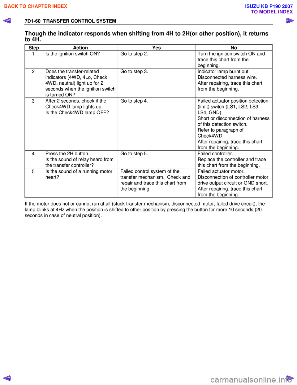
Though the indicator responds when shifting from 4H to 2H(or other position), it returns
to 4H.
Step Action Yes No
1 Is the ignition switch ON? Go to step 2.
Turn the ignition switch ON and
trace this chart from the
beginning.
2 Does the transfer-related
indicators (4W D, 4Lo, Check
4W D, neutral) light up for 2
seconds when the ignition switch
is turned ON? Go to step 3.
Indicator lamp burnt out.
Disconnected harness wire.
After repairing, trace this chart
from the beginning.
3 After 2 seconds, check if the
Check4W D lamp lights up.
Is the Check4W D lamp OFF? Go to step 4.
Failed actuator position detection
(limit) switch (LS1, LS2, LS3,
LS4, GND).
Short or disconnection of harness
of this detection switch.
Refer to paragraph of
Check4W D.
After repairing, trace this chart
from the beginning.
4 Press the 2H button.
Is the sound of relay heard from
the transfer controller? Go to step 5.
Failed controller.
Replace the controller and trace
this chart from the beginning.
5 Is the sound of a running motor
heart? Failed control system of the
transfer mechanism. Check and
repair and trace this chart from
the beginning. Failed actuator motor.
Disconnection of controller motor
drive output circuit or GND short.
After repairing, trace this chart
from the beginning.
If the motor does not or cannot run at all (stuck transfer mechanism, disconnected motor, failed drive circuit), the
lamp blinks at 4Hz when the position is shifted to other position by pressing the button for more 10 seconds (20
seconds in case of neutral position).
BACK TO CHAPTER INDEX
TO MODEL INDEX
ISUZU KB P190 2007