2007 ISUZU KB P190 Circuit
[x] Cancel search: CircuitPage 4939 of 6020
ELECTRICAL-BODY AND CHASSIS 8A-1
SECTION 8A
ELECTRICAL-BODY AND CHASSIS
TABLE OF CONTENTS
PAGE
General Information ........................................................................................................... .........8A- 4
Notes for Working on Electrical Items .......................................................................................8A - 5
Symbols and A bbreviations ..................................................................................................... ..8A- 11
Symbols ....................................................................................................................... ................ 8A- 11
Abbreviations ................................................................................................................. ..............8A- 12
Parts for Electri cal Circuit .................................................................................................. ........8A- 13
Wiring ........................................................................................................................ ...................8A- 13
Fuse .......................................................................................................................... ....................8A- 15
Fusible Link .................................................................................................................. ...............8A- 15
Relay ......................................................................................................................... ....................8A- 16
Diode ......................................................................................................................... ...................8A- 17
Connector ..................................................................................................................... ...............8A- 18
Battery ....................................................................................................................... ...................8A- 19
Reading the Circuit Diagram ................................................................................................... ...8A- 22
Parts Location ................................................................................................................ ..............8A- 22
Circuit Diagram ............................................................................................................... .............8A- 23
Connector List ................................................................................................................ .............8A- 23
Main Data and Specifications .................................................................................................. ...8A- 24
Bulb Specifications ........................................................................................................... ..........8A- 24
Relay and Fuse ................................................................................................................ ............8A- 26
Relay and Fuse Box Location (RHD) .........................................................................................8A- 26
Relay and Fuse Box Location (LHD) ..........................................................................................8A- 27
Relay Location ................................................................................................................ .............8A- 28
Fuse and Slow Blow Fuse Location ...........................................................................................8A- 31
Fuse Location ................................................................................................................. .............8A- 33
Diode Location ................................................................................................................ .............8A- 34
Fuse Block Circuit (C24SE) .................................................................................................... ....8A- 35/36
Fuse Block Circuit (HFV6) ...................................................................................................... .....8A- 37
BACK TO CHAPTER INDEX
TO MODEL INDEX
ISUZU KB P190 2007
Page 4940 of 6020
8A-2 ELECTRICAL-BODY AND CHASSIS
PAGE
Fuse Block Circuit (4JJ1-TC/4JK1-TC (RHD)) SOUTH AFRICA ...............................8A- 39
Fuse Block Circuit (4JJ1-TC/4JK1-TC (RHD)) EXCEPT SOUTH AFRICA ...............8A- 41
Fuse Block Circuit (4JJ1-TC/4JK1-TC) - (LHD) G.EXP .............................................8A- 43
Fuse Block Circuit (4JH1-TC) - (LHD) ........................................................................8A- 45
Fuse Block Circuit (4JA1T (L)) ...................................................................................8A- 47
Grounding Point ..............................................................................................................8 A- 49
Ground Point ...............................................................................................................8A- 49
Ground Point Location ...............................................................................................8A- 89
Cable Harness Routing ...................................................................................................8A- 91
Main Cable Harness (RHD)..........................................................................................8A- 91
Instrument Harness (RHD) ..........................................................................................8A- 92
Main Cable Harness (LHD) ..........................................................................................8A- 93
Instrument Harness (LHD) ..........................................................................................8A- 94
Engine Harness C24SE ...............................................................................................8A- 95
Engine Harness 4JJ1-TC/4JK1-TC ............................................................................8A- 96
Engine Harness 4JH1-TC/4JA1T (L) ...........................................................................8A- 97
Transmission Harness ...............................................................................................8A- 98
System Repair ................................................................................................................. .8A- 100
Start and Charging ......................................................................................................8A- 10 0
Engine Control Module (ECM) ...................................................................................8A- 111
Exhaust Gas Recirculation (EGR) & GLOW; 4JA1T (L) Only ...................................8A- 143
Lighting ...................................................................................................................... ..8A- 149
Front Fog Light ...........................................................................................................8A- 180
Rear Fog Light ............................................................................................................8A- 190
Headlight Leveling ......................................................................................................8A- 19 4
Illumination .................................................................................................................. 8A- 200
Hazard Warning Flasher, Turn Signal Light, Backup Light, Horn and Stoplight ....................................................................................................8A- 213
Dome Light, Spotlight, Map Light and Warning Buzzer ..........................................8A- 245
Windshield Wiper and Washer ..................................................................................8A- 264
Transmission Control Module (TCM) ........................................................................8A- 285
Manual Transmission Shift Assist .............................................................................8A- 298
Meter, Warning Light and Indicator Light .................................................................8A- 303
Heater and Air Conditioning ......................................................................................8A- 371
Power Door Lock ........................................................................................................8A- 386
BACK TO CHAPTER INDEX
TO MODEL INDEX
ISUZU KB P190 2007
Page 4942 of 6020
8A-4 ELECTRICAL-BODY AND CHASSIS
GENERAL INFORMATION
The body and chassis electrical system operates on a twelve volt power supply with negative ground polarity.
The main harness consists of the engine harness, the instrument harness, the body harness, and the chassis
harness.
The harnesses use a split corrugated tube to protect the wires from the elements.
W ire size is determined by current flow, circuit length, and voltage drop.
All wires have color-coded insulation.
W ire color-codes are shown in the circuit diagrams.
This makes it easier to trace circuits and to make the proper connections.
Each circuit consists of the following:
5. Power source – The battery and the alternator
5. W ires – To carry electrical current through the circuit
5. Fuses – To protect the circuit against current overload
5. Relays – To protect voltage drop between the battery and the circuit parts and to protect the switch points against burning
5. Switches – To open and close the circuit
5. Load – Any device, such as a light or motor, which converts the electrical current into useful work
5. Ground – To allow the current to flow back to the power source
BACK TO CHAPTER INDEX TO MODEL INDEXISUZU KB P190 2007
Page 4943 of 6020
ELECTRICAL-BODY AND CHASSIS 8A-5
NOTES FOR WORKING ON ELECTRICAL ITEMS
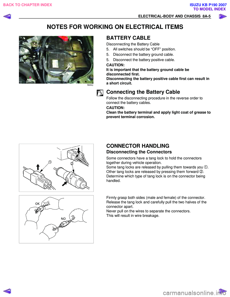
Battery
BATTERY CABLE
Disconnecting the Battery Cable
5. All switches should be “OFF” position.
5. Disconnect the battery ground cable.
5. Disconnect the battery positive cable.
CAUTION:
It is important that the battery ground cable be
disconnected first.
Disconnecting the battery positive cable first can result in
a short circuit.
Connecting the Battery Cable
Follow the disconnecting procedure in the reverse order to
connect the battery cables.
CAUTION:
Clean the battery terminal and apply light coat of grease to
prevent terminal corrosion.
CONNECTOR HANDLING
Disconnecting the Connectors
Some connectors have a tang lock to hold the connectors
together during vehicle operation.
Some tang locks are released by pulling them towards you
1.
Other tang locks are released by pressing them forward
2.
Determine which type of tang lock is on the connector being
handled.
Firmly grasp both sides (male and female) of the connector.
Release the tang lock and carefully pull the two halves of the
connector apart.
Never pull on the wires to separate the connectors.
This will result in wire breakage.
BACK TO CHAPTER INDEX TO MODEL INDEXISUZU KB P190 2007
Page 4944 of 6020
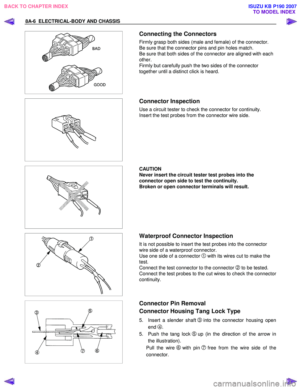
8A-6 ELECTRICAL-BODY AND CHASSIS
Connecting the Connectors
Firmly grasp both sides (male and female) of the connector.
Be sure that the connector pins and pin holes match.
Be sure that both sides of the connector are aligned with each
other.
Firmly but carefully push the two sides of the connector
together until a distinct click is heard.
Connector Inspection
Use a circuit tester to check the connector for continuity.
Insert the test probes from the connector wire side.
CAUTION
Never insert the circuit tester test probes into the
connector open side to test the continuity.
Broken or open connector terminals will result.
Waterproof Connector Inspection
It is not possible to insert the test probes into the connector
wire side of a waterproof connector.
Use one side of a connector
1 with its wires cut to make the
test.
Connect the test connector to the connector
2 to be tested.
Connect the test probes to the cut wires to check the connecto
r
continuity.
Connector Pin Removal
Connector Housing Tang Lock Type
5. Insert a slender shaft 3into the connector housing open
end
4.
5. Push the tang lock
5up (in the direction of the arrow in
the illustration).
Pull the wire
6 with pin 7free from the wire side of the
connector.
BACK TO CHAPTER INDEX TO MODEL INDEXISUZU KB P190 2007
Page 4945 of 6020
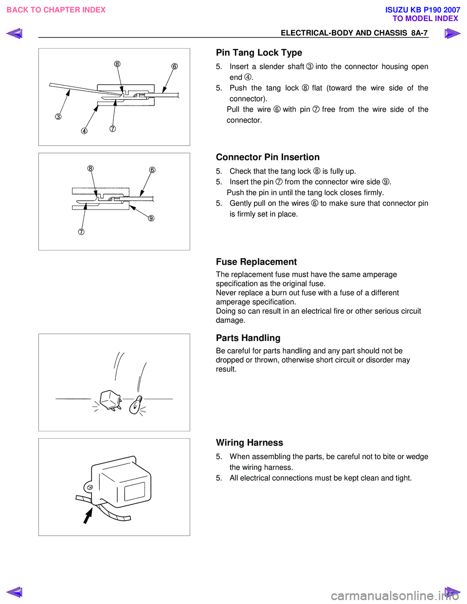
ELECTRICAL-BODY AND CHASSIS 8A-7
Pin Tang Lock Type
5. Insert a slender shaft 3into the connector housing open
end
4.
5. Push the tang lock
8flat (toward the wire side of the
connector).
Pull the wire
6 with pin 7free from the wire side of the
connector.
Connector Pin Insertion
5. Check that the tang lock 8 is fully up.
5. Insert the pin
7 from the connector wire side 9.
Push the pin in until the tang lock closes firmly.
5. Gently pull on the wires
6to make sure that connector pin
is firmly set in place.
Fuse Replacement
The replacement fuse must have the same amperage
specification as the original fuse.
Never replace a burn out fuse with a fuse of a different
amperage specification.
Doing so can result in an electrical fire or other serious circuit
damage.
Parts Handling
Be careful for parts handling and any part should not be
dropped or thrown, otherwise short circuit or disorder may
result.
Wiring Harness
5. W hen assembling the parts, be careful not to bite or wedge
the wiring harness.
5. All electrical connections must be kept clean and tight.
BACK TO CHAPTER INDEX TO MODEL INDEXISUZU KB P190 2007
Page 4950 of 6020
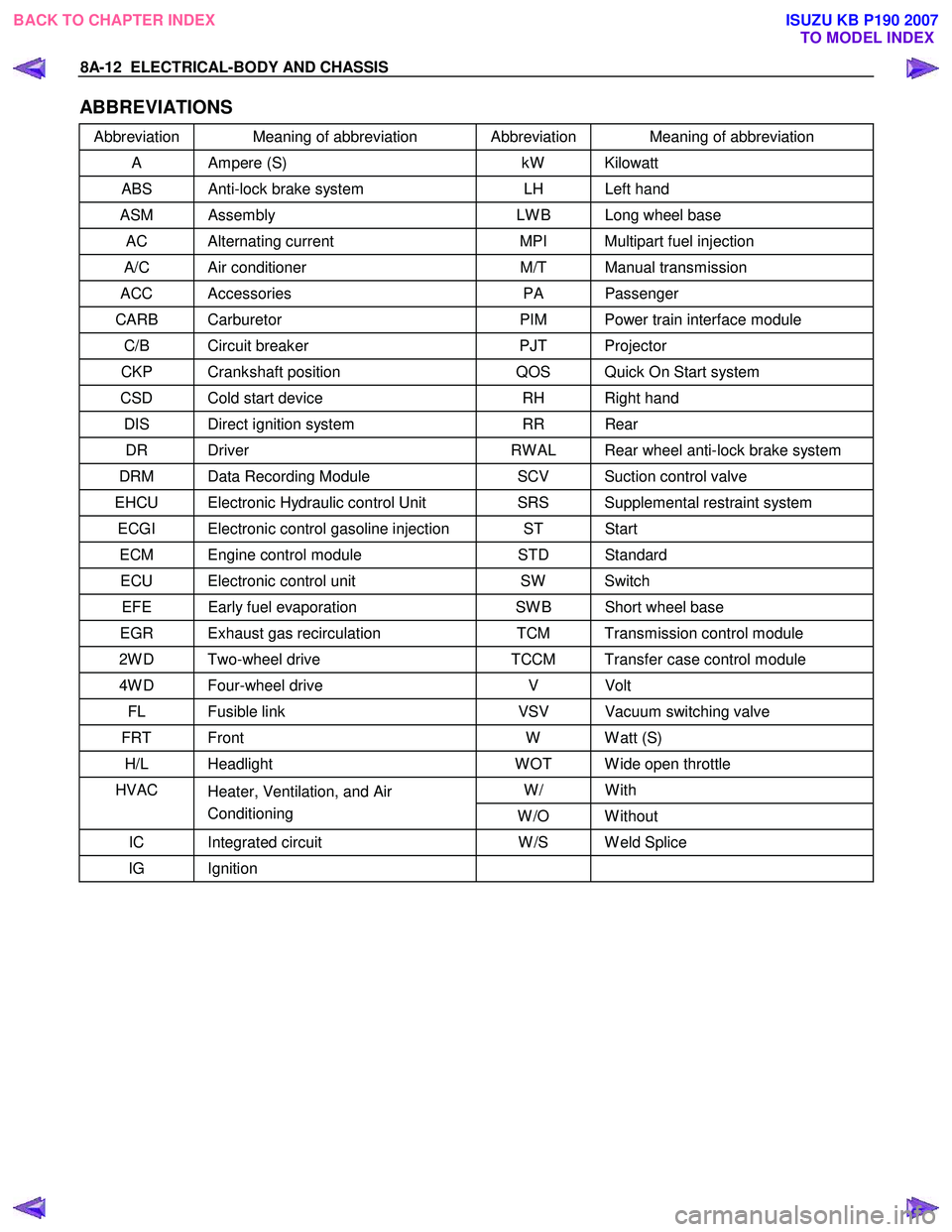
8A-12 ELECTRICAL-BODY AND CHASSIS
ABBREVIATIONS
Abbreviation Meaning of abbreviation Abbreviation Meaning of abbreviation
A Ampere (S) kW Kilowatt
ABS Anti-lock brake system LH Left hand
ASM Assembly LW B Long wheel base
AC Alternating current MPI Multipart fuel injection
A/C Air conditioner M/T Manual transmission
ACC Accessories PA Passenger
CARB Carburetor PIM Power train interface module
C/B Circuit breaker PJT Projector
CKP Crankshaft position QOS Quick On Start system
CSD Cold start device RH Right hand
DIS Direct ignition system RR Rear
DR Driver RW AL Rear wheel anti-lock brake system
DRM Data Recording Module SCV Suction control valve
EHCU Electronic Hydraulic control Unit SRS Supplemental restraint system
ECGI Electronic control gasoline injection ST Start
ECM Engine control module STD Standard
ECU Electronic control unit SW Switch
EFE Early fuel evaporation SW B Short wheel base
EGR Exhaust gas recirculation TCM Transmission control module
2W D Two-wheel drive TCCM Transfer case control module
4W D Four-wheel drive V Volt
FL Fusible link VSV Vacuum switching valve
FRT Front W W att (S)
H/L Headlight W OT W ide open throttle
W/ With HVAC
Heater, Ventilation, and Air
Conditioning W /O W ithout
IC Integrated circuit W /S W eld Splice
IG Ignition
BACK TO CHAPTER INDEX
TO MODEL INDEXISUZU KB P190 2007
Page 4951 of 6020
ELECTRICAL-BODY AND CHASSIS 8A-13
PARTS FOR ELECTRICAL CIRCUIT
WIRING
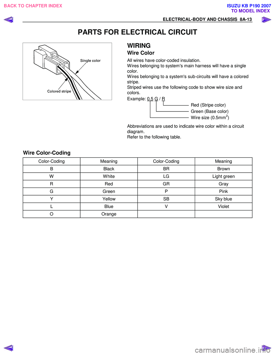
Wire Color
All wires have color-coded insulation.
W ires belonging to system's main harness will have a single
color.
W ires belonging to a system's sub-circuits will have a colored
stripe.
Striped wires use the following code to show wire size and
colors.
Example: 0.5 G
/ R
Red (Stripe color)
Green (Base color)
W ire size (0.5mm
2)
Abbreviations are used to indicate wire color within a circuit
diagram.
Refer to the following table.
Wire Color-Coding
Color-Coding Meaning Color-Coding Meaning
B Black BR Brown
W W hite LG Light green
R Red GR Gray
G Green P Pink
Y Yellow SB Sky blue
L Blue V Violet
O Orange
BACK TO CHAPTER INDEX
TO MODEL INDEXISUZU KB P190 2007