2007 ISUZU KB P190 ignition
[x] Cancel search: ignitionPage 3931 of 6020
Automatic Transmission – 4L60E – On-vehicle Servicing Page 7C4–18
Ensure the four wheels are off the ground
before performing the starting test.
4 W ith the ignition switched to the ON position, check if the engine can only be started in the Park and Neutral shift selector positions and ensure the back-up lamps illuminate when Reverse is selected. A further minor adjustment
may be required to achieve this state.
NOTE
To gain access to the rear attaching screw (11) it
will be necessary to remove the connector.
5 After the switch has been adjusted, tighten the rear attaching screw (11) to the correct torque specification. Neutral start and back-up lamp switch
attaching screw torque specification .................. 25.0 Nm
6 Reinstall the connector and the CPA securing pin.
7 Remove the switch front attaching screw (1).
8 Install the heat shield (3) and tighten the attaching screws (1 and 2) to the correct torque specification.
Heat shield front attaching screw
torque specification ............................................ 25.0 Nm
Heat shield rear attaching screw torque specification ..............................................9.0 Nm
9 Lower the vehicle to the ground and re-check the operation of the neutral start and back-up lamp switch. The vehicle must start only with the shift selector in the Park or Neutral positions and the back-up lamps should only
illuminate when Reverse is selected.
3.5 Vehicle Speed Sensor
NOTE
For the speed sensor fitted to four wheel drive
vehicles (4WD), refer to 7D Transfer Case and
Adaptor Housing.
Remove
1 Raise the vehicle and support in a safe manner, refer
to 0A General Information for the location of support
points.
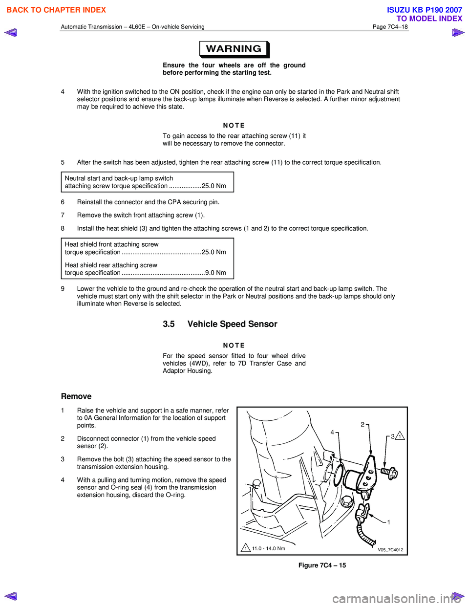
2 Disconnect connector (1) from the vehicle speed sensor (2).
3 Remove the bolt (3) attaching the speed sensor to the transmission extension housing.
4 With a pulling and turning motion, remove the speed sensor and O-ring seal (4) from the transmission
extension housing, discard the O-ring.
Figure 7C4 – 15
BACK TO CHAPTER INDEX
TO MODEL INDEX
ISUZU KB P190 2007
Page 3956 of 6020
Automatic Transmission – 4L60E – On-vehicle Servicing Page 7C4–43
If the verifier disc does not clip into place, the
quick-connect fitting is not engaged, rectify
as required.
10 As a security check, push and clip each verification disc into place over the quick-connect fittings. If difficulty is experienced, repeat the installation process until the verification disc can be clipped into place over the radiator
quick-connect fitting.
11 Snap the outlet cooler line (4) in the clip (5) of the radiator fan shroud.
12 Ensure the routeing of the cooler lines is correct and there is no fouling of the lines.
13 Tighten the screw attaching the cooler lines bracket to the correct torque specifications.
Transmission cooler lines bracket
attaching screw torque specification .................. 23.0 Nm
14 If required, top up the transmission fluid level (cold).
15 Start the engine and check for any fluid leak at the fittings. If a leak is found, stop the engine and rectify the leak.
16 Check and top up the transmission fluid to the correct level as required, refer to 2.1 Transmission Fluid.
3.18 Transmission Assembly
Remove
Disconnection of the battery affects certain
vehicle electronic systems. Refer to 6D1-3
Battery, before disconnecting the battery.
1 Disconnect the battery ground lead.
2 Raise the vehicle and support in a safe manner, refer to 0A General Information for the location of support points.
3 Remove the heat shield from the neutral start and back-up lamp switch, gently prise the selector cable from the transmission external manual shaft linkage and remove the selector cable from the bracket, refer to
3.3 Selector Cable Assembly.
4 Disconnect the harness connectors from the following:
a Vehicle speed sensor, refer to 3.5 Vehicle Speed Sensor.
b Neutral start and back-up switch, refer to 3.4 Neutral Start and Back-up Lamp Switch.
c For the following on four wheel drive vehicles (4W D), refer to 7D Transfer Case and Adaptor Housing:
• neutral switch,
• 2WD – 4WD shift actuator switch,
• speed sensor.
NOTE
If the battery is connected, avoid turning the
ignition switch to the ON position, as the transfer
case control module (TTCM) must first be
removed (memory to be cleared as Check 4W D
Indicator will light).
5 Remove the following components: a Front and centre exhaust assemblies, refer to 6F Exhaust System.
BACK TO CHAPTER INDEX
TO MODEL INDEX
ISUZU KB P190 2007
Page 3960 of 6020
Automatic Transmission – 4L60E – On-vehicle Servicing Page 7C4–47
14 Reconnect the fuel and EVAP pipes three brackets and clips, refer to 6C Fuel System – V6.
15 Reinstall the following components:
a Starter motor, refer to 6D1-2 Starting System.
b Transmission support, refer to 3.7 Transmission Support and Mount.
c Front and centre exhaust assemblies, refer to 6F Exhaust System.
d Rear propeller shaft and for 4WD front propeller shaft, refer to 4A Propeller Shaft.
16 Reconnect the harness connectors to the following: a Vehicle speed sensor, refer to 3.5 Vehicle Speed Sensor.
b Neutral start and back-up switch, refer to 3.4 Neutral Start and Back-up Lamp Switch.
c For the following on 4W D vehicles, refer to 7D Transfer Case and Adaptor Housing:
• neutral switch,
• 2WD – 4WD shift actuator switch,
• speed sensor.
17 Reinstall the selector cable to the transmission external manual shaft linkage, secure the selector cable to the bracket and attach the heat shield to the neutral start and back-up lamp switch, refer to 3.3 Selector Cable
Assembly.
18 Perform a reverse flush of the cooler lines and a flow rate test, refer to 2.2 Reverse Flush and Flow Rate, if either of the following applies:
• the transmission fluid is contaminated,
• the transmission has been replaced,
• the torque converter has been replaced, or
• the transmission oil pump has been replaced.
19 Lower the vehicle to the ground.
20 If required, top up the transmission fluid level (cold).
21 Reconnect the battery ground lead.
22 Start the engine and check for any fluid leaking at the fittings. If a leak is found, stop the engine and rectify the leak.
23 Road test until the transmission has reached operating temperature. Re-check the fluid level and for any fluid leaks, refer to 2.1 Transmission Fluid.
3.19 Transmission Control Module
Remove
1 Ensure the ignition switch is in the OFF position.
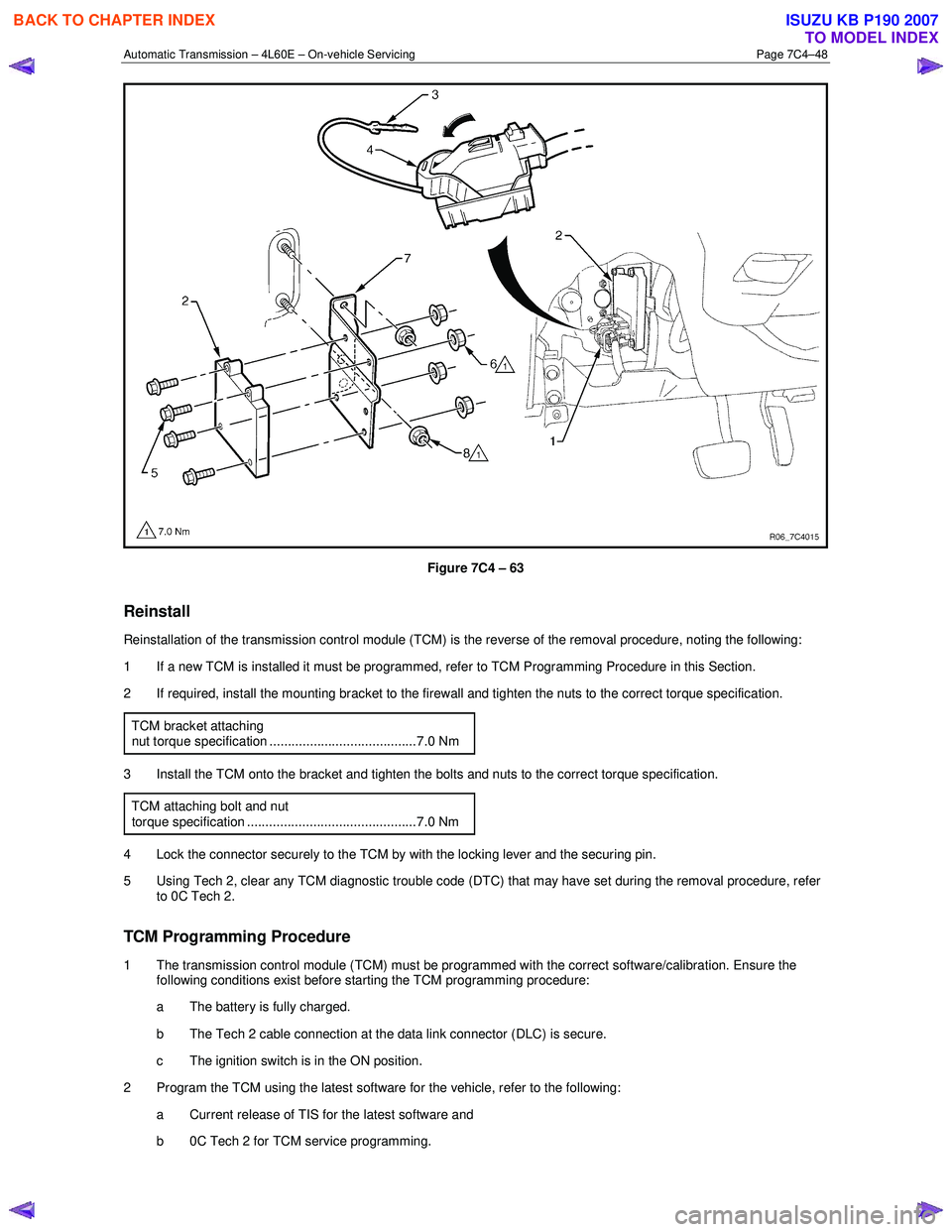
2 Disconnect the connector (1) from the transmission control module (TCM) (2) as follows, refer to Figure 7C4 – 63: a remove the securing pin (3),
b press the locking tab and swing the lever (4) to free the connector,
c remove the connector.
3 Remove the four bolts (5) and nuts (6), then the TCM from the mounting bracket (7).
4 If required, remove the two nuts (8) and the mounting bracket from the firewall.
BACK TO CHAPTER INDEX
TO MODEL INDEX
ISUZU KB P190 2007
Page 3961 of 6020
Automatic Transmission – 4L60E – On-vehicle Servicing Page 7C4–48
Figure 7C4 – 63
Reinstall
Reinstallation of the transmission control module (TCM) is the reverse of the removal procedure, noting the following:
1 If a new TCM is installed it must be programmed, refer to TCM Programming Procedure in this Section.
2 If required, install the mounting bracket to the firewall and tighten the nuts to the correct torque specification.
TCM bracket attaching
nut torque specification ........................................7.0 Nm
3 Install the TCM onto the bracket and tighten the bolts and nuts to the correct torque specification. TCM attaching bolt and nut
torque specification ..............................................7.0 Nm
4 Lock the connector securely to the TCM by with the locking lever and the securing pin.
5 Using Tech 2, clear any TCM diagnostic trouble code (DTC) that may have set during the removal procedure, refer to 0C Tech 2.
TCM Programming Procedure
1 The transmission control module (TCM) must be programmed with the correct software/calibration. Ensure the following conditions exist before starting the TCM programming procedure:
a The battery is fully charged.
b The Tech 2 cable connection at the data link connector (DLC) is secure.
c The ignition switch is in the ON position.
2 Program the TCM using the latest software for the vehicle, refer to the following: a Current release of TIS for the latest software and
b 0C Tech 2 for TCM service programming.
BACK TO CHAPTER INDEX
TO MODEL INDEX
ISUZU KB P190 2007
Page 3978 of 6020
7A2-12 TRANSMISSION CONTROL SYSTEM (AW30–40LE)
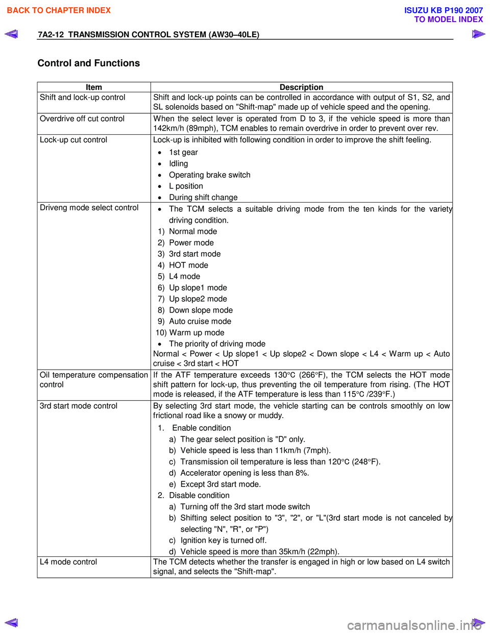
Control and Functions
Item Description
Shift and lock-up control Shift and lock-up points can be controlled in accordance with output of S1, S2, and SL solenoids based on "Shift-map" made up of vehicle speed and the opening.
Overdrive off cut control W hen the select lever is operated from D to 3, if the vehicle speed is more than 142km/h (89mph), TCM enables to remain overdrive in order to prevent over rev.
Lock-up cut control Lock-up is inhibited with following condition in order to improve the shift feeling.
• 1st gear
• Idling
• Operating brake switch
• L position
• During shift change
Driveng mode select control
• The TCM selects a suitable driving mode from the ten kinds for the variety
driving condition.
1) Normal mode
2) Power mode
3) 3rd start mode
4) HOT mode
5) L4 mode
6) Up slope1 mode
7) Up slope2 mode
8) Down slope mode
9) Auto cruise mode
10) W arm up mode • The priority of driving mode
Normal < Power < Up slope1 < Up slope2 < Down slope < L4 < W arm up < Auto
cruise < 3rd start < HOT
Oil temperature compensation
control If the ATF temperature exceeds 130
°C (266 °F), the TCM selects the HOT mode
shift pattern for lock-up, thus preventing the oil temperature from rising. (The HOT
mode is released, if the ATF temperature is less than 115 °C /239 °F.)
3rd start mode control By selecting 3rd start mode, the vehicle starting can be controls smoothly on low
frictional road like a snowy or muddy.
1. Enable condition a) The gear select position is "D" only.
b) Vehicle speed is less than 11km/h (7mph).
c) Transmission oil temperature is less than 120 °C (248 °F).
d) Accelerator opening is less than 8%.
e) Except 3rd start mode.
2. Disable condition a) Turning off the 3rd start mode switch
b) Shifting select position to "3", "2", or "L"(3rd start mode is not canceled b
y
selecting "N", "R", or "P")
c) Ignition key is turned off.
d) Vehicle speed is more than 35km/h (22mph).
L4 mode control The TCM detects whether the transfer is engaged in high or low based on L4 switch
signal, and selects the "Shift-map".
BACK TO CHAPTER INDEX
TO MODEL INDEX
ISUZU KB P190 2007
Page 3982 of 6020
7A2-16 TRANSMISSION CONTROL SYSTEM (AW30–40LE)
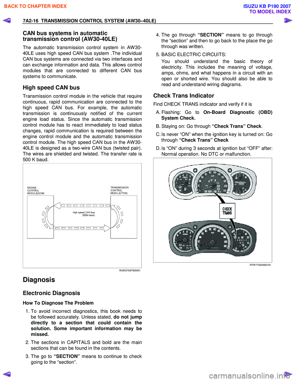
CAN bus systems in automatic
transmission control (AW30-40LE)
The automatic transmission control system in AW 30-
40LE uses high speed CAN bus system .The individual
CAN bus systems are connected via two interfaces and
can exchange information and data. This allows control
modules that are connected to different CAN bus
systems to communicate.
High speed CAN bus
Transmission control module in the vehicle that require
continuous, rapid communication are connected to the
high speed CAN bus. For example, the automatic
transmission is continuously notified of the current
engine load status. Since the automatic transmission
control module has to react immediately to load status
changes, rapid communication is required between the
engine control module and the automatic transmission
control module. The high speed CAN bus in the AW 30-
40LE is designed as a two-wire CAN bus (twisted pair).
The wires are shielded and twisted. The transfer rate is
500 K baud.
RUW 37ASF000401
Diagnosis
Electronic Diagnosis
How To Diagnose The Problem
1. To avoid incorrect diagnostics, this book needs to
be followed accurately. Unless stated, do not jump
directly to a section that could contain the
solution. Some important information may be
missed.
2. The sections in CAPITALS and bold are the main
sections that can be found in the contents.
3. The go to “SECTION” means to continue to check
going to the “section”.
4. The go through “SECTION” means to go through
the “section” and then to go back to the place the go
through was written.
5. BASIC ELECTRIC CIRCUITS:
You should understand the basic theory o
f
electricity. This includes the meaning of voltage,
amps, ohms, and what happens in a circuit with an
open or shorted wire. You should also be able to
read and understand wiring diagrams.
Check Trans Indicator
Find CHECK TRANS indicator and verify if it is
A. Flashing: Go to On-Board Diagnostic (OBD)
System Check.
B. Staying on: Go through “Check Trans” Check.
C. Is never “ON” when the ignition key is turned on: Go through “Check Trans” Check
D. Is “ON” during 3 seconds at ignition but “OFF” after: Normal operation. No DTC or malfunction.
RTW 77ASH000101
BACK TO CHAPTER INDEX
TO MODEL INDEX
ISUZU KB P190 2007
Page 3983 of 6020
TRANSMISSION CONTROL SYSTEM (AW30–40LE) 7A2-17
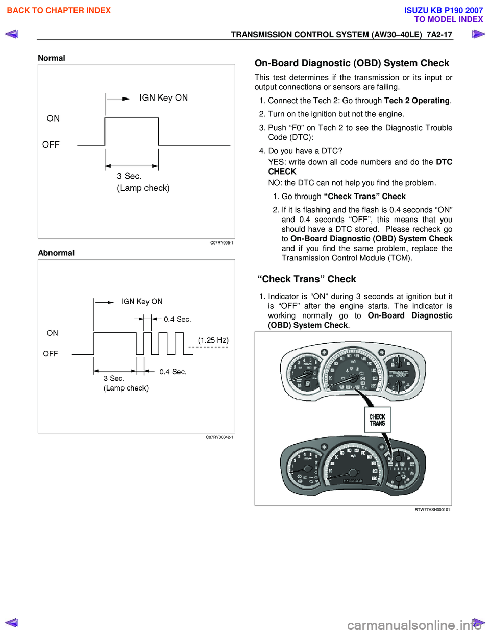
Normal
C07RY005-1
Abnormal
C07RY00042-1
On-Board Diagnostic (OBD) System Check
This test determines if the transmission or its input or
output connections or sensors are failing.
1. Connect the Tech 2: Go through Tech 2 Operating.
2. Turn on the ignition but not the engine.
3. Push “F0” on Tech 2 to see the Diagnostic Trouble Code (DTC):
4. Do you have a DTC? YES: write down all code numbers and do the DTC
CHECK
NO: the DTC can not help you find the problem.
1. Go through “Check Trans” Check
2. If it is flashing and the flash is 0.4 seconds “ON”
and 0.4 seconds “OFF”, this means that you
should have a DTC stored. Please recheck go
to On-Board Diagnostic (OBD) System Chec
k
and if you find the same problem, replace the
Transmission Control Module (TCM).
“Check Trans” Check
1. Indicator is “ON” during 3 seconds at ignition but it
is “OFF” after the engine starts. The indicator is
working normally go to On-Board Diagnostic
(OBD) System Check .
RTW 77ASH000101
BACK TO CHAPTER INDEX
TO MODEL INDEX
ISUZU KB P190 2007
Page 3984 of 6020
7A2-18 TRANSMISSION CONTROL SYSTEM (AW30–40LE)
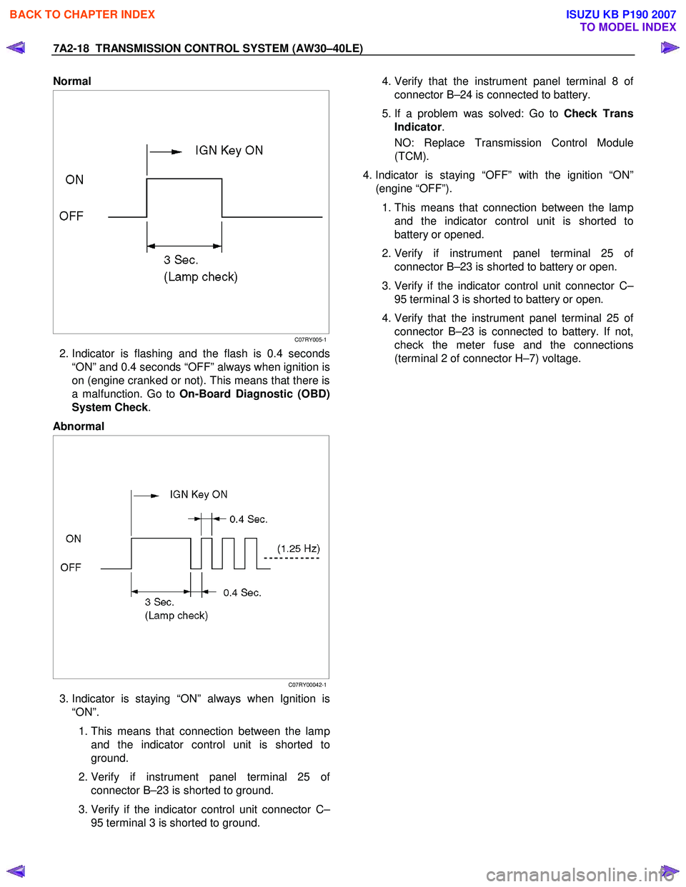
Normal
C07RY005-1
2. Indicator is flashing and the flash is 0.4 seconds
“ON” and 0.4 seconds “OFF” always when ignition is
on (engine cranked or not). This means that there is
a malfunction. Go to On-Board Diagnostic (OBD)
System Check .
Abnormal
C07RY00042-1
3. Indicator is staying “ON” always when Ignition is
“ON”.
1. This means that connection between the lamp
and the indicator control unit is shorted to
ground.
2. Verify if instrument panel terminal 25 o
f
connector B–23 is shorted to ground.
3. Verify if the indicator control unit connector C–
95 terminal 3 is shorted to ground.
4. Verify that the instrument panel terminal 8 o
f
connector B–24 is connected to battery.
5. If a problem was solved: Go to Check Trans
Indicator .
NO: Replace Transmission Control Module
(TCM).
4. Indicator is staying “OFF” with the ignition “ON”
(engine “OFF”).
1. This means that connection between the lamp
and the indicator control unit is shorted to
battery or opened.
2. Verify if instrument panel terminal 25 o
f
connector B–23 is shorted to battery or open.
3. Verify if the indicator control unit connector C–
95 terminal 3 is shorted to battery or open.
4. Verify that the instrument panel terminal 25 o
f
connector B–23 is connected to battery. If not,
check the meter fuse and the connections
(terminal 2 of connector H–7) voltage.
BACK TO CHAPTER INDEX
TO MODEL INDEX
ISUZU KB P190 2007