2007 ISUZU KB P190 ECU
[x] Cancel search: ECUPage 1582 of 6020
FUEL SYSTEM (4JK1/4JJ1) 6C-41
Removal
Note: W hen repairs to the fuel system have been
completed, start the engine and check the fuel system
for loose connections or leakage. For the fuel system
diagnosis, see Section "Drivability and Emission".
1. Disconnect the battery ground cable.
2. Slowly loosen the fuel filler cap.
Note: Be careful that fuel does not spout out because o
f
change of pressure in the fuel tank.
Note: Cover opening of the filler neck to prevent an
y
dust entering. 3. Jack up the vehicle.
4. Disconnect the quick connector (5) of the fuel tube at the fuel cooler way.
5. Remove fuel return hose (8) from the pipe.
6. Remove fixing bolt (7) of the bracket fuel coole
r
and remove bracket fuel cooler (6).
Note: Cover the opening of the pipe to prevent any dust
and fuel leakage.
Note: For remove fuel cooler, Remove bolts (10) of the
fuel cooler and remove fuel cooler.
7. Support underneath of the fuel tank with a lifter.
8. Remove the inner liner of the wheel house at rea
r
left side.
9. Remove fixing bolt of the filler neck from the body.
10. Disconnect the quick connector (5) of the fuel tube from the fuel pipe and the evapo tube from evapo
joint connector.
Note: Cover the quick connector to prevent any dust
entering and prevent fuel leakage.
Note: Refer to "Fuel Tube/Quick Connector Fittings" in
this section when performing any repairs.
11. Remove fixing bolt (1) of the tank band and remove the tank band (2).
12. Disconnect the pump and sender connector on the fuel pump and remove the harness from the weld
clip on the fuel tank.
13. Lower the fuel tank (3).
Note: W hen lowering the fuel tank from the vehicle, do
not scratch the hoses and tubes by contact with othe
r
parts.
Installation
1. Raise the fuel tank.
Note: W hen raising the fuel tank to the vehicle, do not
scratch the hoses and tubes by contact with other parts.
2. Connect the pump and sender connector to the fuel pump and install the harness to the weld clip
on the tank.
Note: The connector must be securely connected
against the stopper.
3. Install the tank band and fasten bolt.
Torque: 68 N ⋅
⋅⋅
⋅
m (6.9 kg ⋅
⋅⋅
⋅
m /50 lb ft)
Note: The anchor of the tank band must be securely
installed to the guide hole on the frame.
4. Connect the quick connector of the fuel tube to the fuel pipe and the evapo tube from evapo joint
connector.
Note: Pull off the left checker on the fuel pipe.
Note: Refer to "Fuel Tube/Quick Connector Fittings" in
this section when performing any repairs.
5. Install the filler neck to the body with bolt.
Note: For install the fuel cooler to the bracket with bolt.
Torque: 6.5 N ⋅
⋅⋅
⋅
m (0.7 kg ⋅
⋅⋅
⋅
m /61 lb in)
6. Install the bracket to Frame with bolt. Torque: 48 N ⋅
⋅⋅
⋅
m (4.9 kg ⋅
⋅⋅
⋅
m /35 lb ft)
7. Install the fuel return hose at the fuel cooler way.
8. Install the quick connector at the fuel cooler way.
9. Install the inner liner of the wheel house at rear left side.
10. Remove lifter from the fuel tank.
11. Lower the vehicle.
12. Tighten the filler cap until at least three clicks.
13. Connect the battery ground cable.
BACK TO CHAPTER INDEX
TO MODEL INDEX
ISUZU KB P190 2007
Page 1586 of 6020
FUEL SYSTEM (4JK1/4JJ1) 6C-45
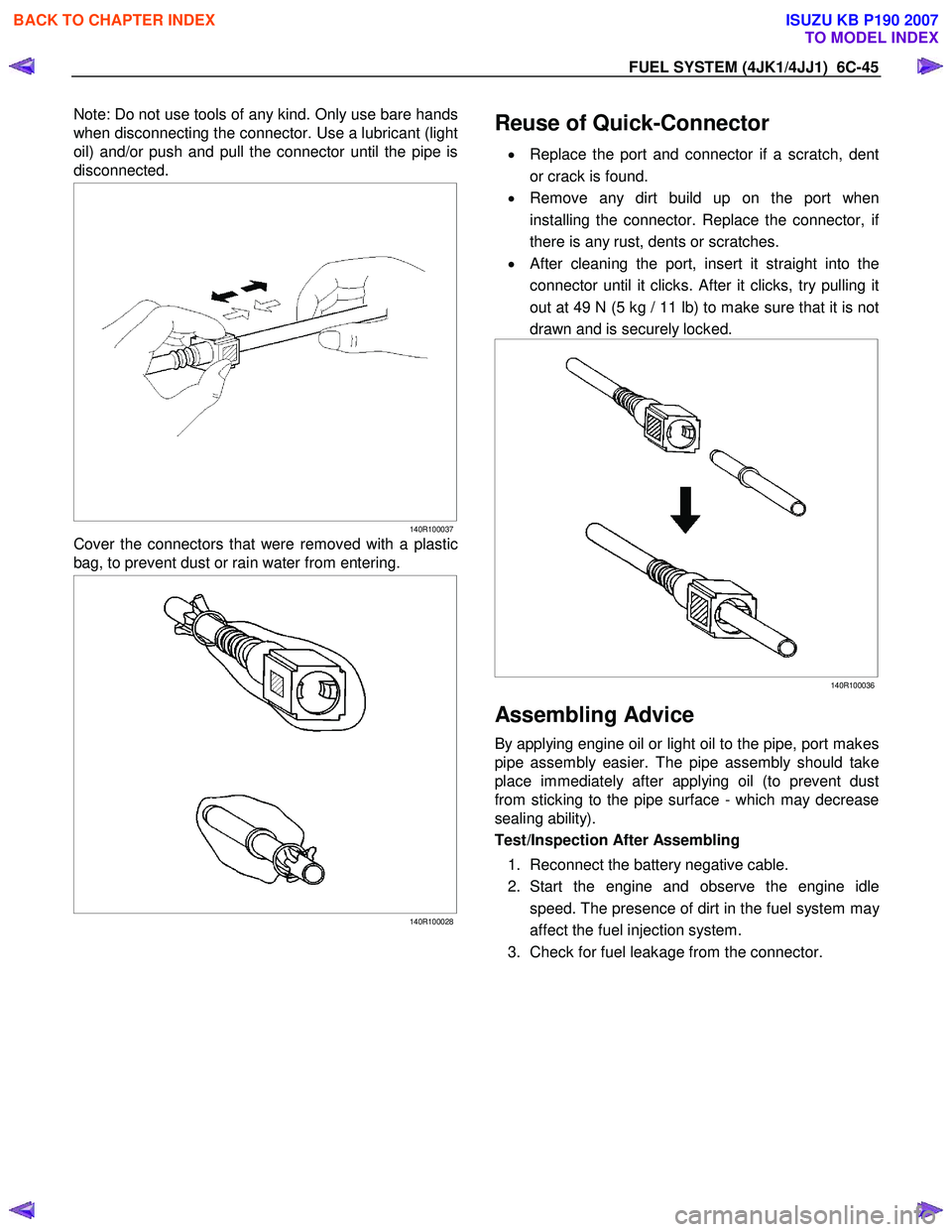
Note: Do not use tools of any kind. Only use bare hands
when disconnecting the connector. Use a lubricant (light
oil) and/or push and pull the connector until the pipe is
disconnected.
140R100037
Cover the connectors that were removed with a plastic
bag, to prevent dust or rain water from entering.
140R100028
Reuse of Quick-Connector
•
Replace the port and connector if a scratch, dent
or crack is found.
• Remove any dirt build up on the port when
installing the connector. Replace the connector, i
f
there is any rust, dents or scratches.
• After cleaning the port, insert it straight into the
connector until it clicks. After it clicks, try pulling it
out at 49 N (5 kg / 11 lb) to make sure that it is not
drawn and is securely locked.
140R100036
Assembling Advice
By applying engine oil or light oil to the pipe, port makes
pipe assembly easier. The pipe assembly should take
place immediately after applying oil (to prevent dust
from sticking to the pipe surface - which may decrease
sealing ability).
Test/Inspection After Assembling
1. Reconnect the battery negative cable.
2. Start the engine and observe the engine idle speed. The presence of dirt in the fuel system ma
y
affect the fuel injection system.
3. Check for fuel leakage from the connector.
BACK TO CHAPTER INDEX
TO MODEL INDEX
ISUZU KB P190 2007
Page 1598 of 6020
6D-10 ENGINE ELECTRICAL (4JK1/4JJ1)
Disassembly
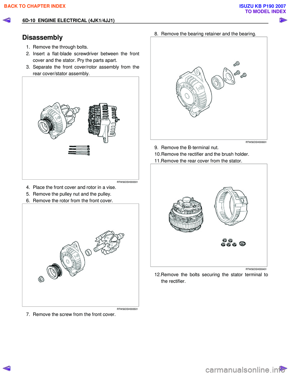
1. Remove the through bolts.
2. Insert a flat-blade screwdriver between the front cover and the stator. Pry the parts apart.
3. Separate the front cover/rotor assembly from the rear cover/stator assembly.
RTW 56DSH000301
4. Place the front cover and rotor in a vise.
5. Remove the pulley nut and the pulley.
6. Remove the rotor from the front cover.
RTW 56DSH000501
7. Remove the screw from the front cover.
8. Remove the bearing retainer and the bearing.
RTW 56DSH000601
9. Remove the B-terminal nut.
10. Remove the rectifier and the brush holder.
11.Remove the rear cover from the stator.
RTW 56DSH000401
12.Remove the bolts securing the stator terminal to
the rectifier.
BACK TO CHAPTER INDEX
TO MODEL INDEX
ISUZU KB P190 2007
Page 1599 of 6020
ENGINE ELECTRICAL (4JK1/4JJ1) 6D-11
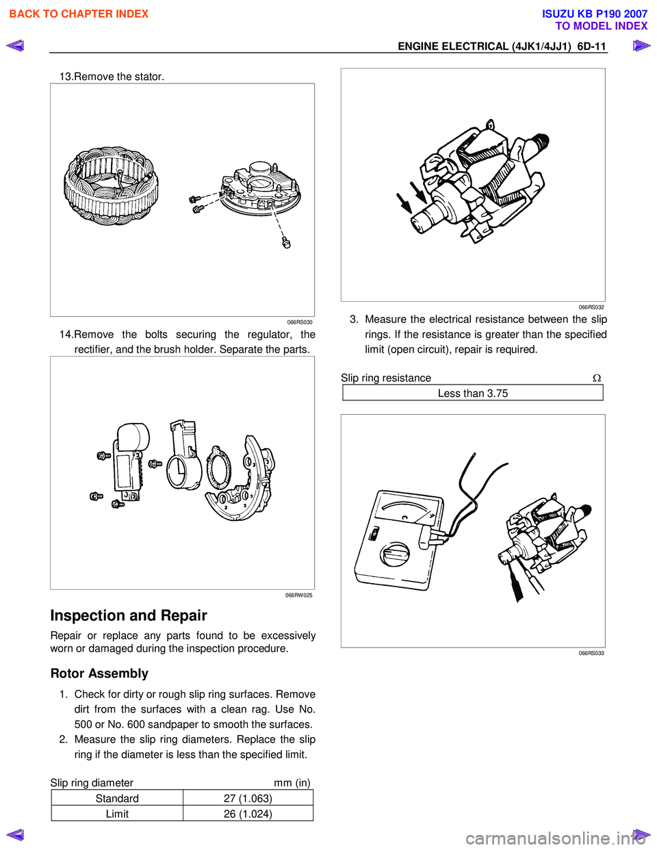
13.Remove the stator.
066RS030
14.Remove the bolts securing the regulator, the
rectifier, and the brush holder. Separate the parts.
066RW 025
Inspection and Repair
Repair or replace any parts found to be excessively
worn or damaged during the inspection procedure.
Rotor Assembly
1. Check for dirty or rough slip ring surfaces. Remove
dirt from the surfaces with a clean rag. Use No.
500 or No. 600 sandpaper to smooth the surfaces.
2. Measure the slip ring diameters. Replace the slip ring if the diameter is less than the specified limit.
Slip ring diameter mm (in)
Standard 27 (1.063)
Limit 26 (1.024)
066RS032
3. Measure the electrical resistance between the slip
rings. If the resistance is greater than the specified
limit (open circuit), repair is required.
Slip ring resistance Ω
Less than 3.75
066RS033
BACK TO CHAPTER INDEX
TO MODEL INDEX
ISUZU KB P190 2007
Page 1602 of 6020
6D-14 ENGINE ELECTRICAL (4JK1/4JJ1)
Reassembly
Follow the disassembly steps in reverse order to
reassemble the generator. Pay close attention to the
items below.
• Be very careful not to reverse battery polarity.
Reversed battery polarity will destroy the rectifie
r
diodes.
• Do not ground the generator B-terminal. Heat and
fire damage to the harness will result.
• If using a fast charge procedure, be sure to
disconnect the battery positive cable. If you do not,
the rectifier diodes will be exposed to high positive
voltage that will destroy them.
• Be very careful to reassemble the parts to thei
r
original positions. Particular care must be taken
with insulated parts.
• Carefully clean all insulated parts so that they are
completely free of oil and/or grease.
• Be sure that B-terminal twist-type stoppers (round
terminal) are securely inserted before tightening
the nuts.
Final Assembly
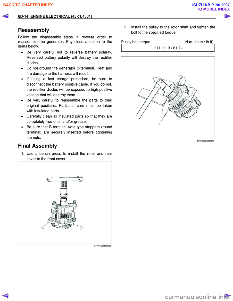
1. Use a bench press to install the rotor and rear
cover to the front cover.
RTW 56DSH000201
2. Install the pulley to the rotor shaft and tighten the
bolt to the specified torque.
Pulley bolt torque N
⋅m (kg⋅m / lb ft)
111 (11.3 / 81.7)
RTW 56DSH000101
BACK TO CHAPTER INDEX
TO MODEL INDEX
ISUZU KB P190 2007
Page 1621 of 6020
6E-4 ENGINE CONTROL SYSTEM (4JK1/4JJ1)
Diagnostic Trouble Code (DTC) Type
Definitions
Emission Related DTC
Action Taken When the DTC Sets - Type A • The ECM illuminates the malfunction indicator lamp (MIL) when the diagnostic runs and fails.
• The ECM records the operating conditions at the time the diagnostic fails. The ECM stores this
information in the Freeze Frame/ Failure Records.
Action Taken When the DTC Sets - Type B • The ECM illuminates the MIL on the second consecutive driving cycle when the diagnostic runs
and fails.
• The ECM records the operating conditions at the time the diagnostic fails. The first time the
diagnostic fails, the ECM stores this information in
the Failure Records. If the diagnostic reports a
failure on the second consecutive driving cycle, the
ECM records the operating conditions at the time
of failure and stores this information in the Freeze
Frame and updates the Failure Records.
Conditions for Clearing the MIL/ DTC - Type A or
Ty p e B
• The ECM turns OFF the MIL after 3 consecutive driving cycles when the diagnostic runs and does
not fail. (Euro 4 Specification)
• The ECM turns OFF the MIL after 1 driving cycle when the diagnostic runs and does not fail. (Except
Euro 4 Specification)
• A current DTC clears when the diagnostic runs and passes after 1 driving cycle.
• A history DTC clears after 40 consecutive warm-up cycles, if no failures are reported. • Use a scan tool to clear the MIL and the DTC.
Non-Emissions Related DTCs
Action Taken When the DTC Sets - Type C
• The ECM illuminates the Service Vehicle Soon (SVS) lamp when the diagnostic runs and fails.
• The ECM records the operating conditions at the time the diagnostic fails. The ECM stores this
information in the Failure Records.
Conditions for Clearing the SVS Lamp/ DTC - Type
C
• The ECM turns OFF the SVS lamp after 1 driving cycle when the diagnostic runs and does not fail.
• A current DTC clears when the diagnostic runs and passes after 1 driving cycle.
• A history DTC clears after 40 consecutive warm-up cycles, if no failures are reported.
• Use a scan tool to clear the SVS lamp and the DTC.
Action Taken When the DTC Sets - Type D • The ECM will not illuminate the MIL or SVS lamp.
• The ECM records the operating conditions at the time the diagnostic fails. The ECM stores this
information in the Failure Records.
Conditions for Clearing the DTC - Type D • A current DTC clears when the diagnostic runs and passes after 1 driving cycle.
• A history DTC clears after 40 consecutive warm-up cycles, if no failures are reported.
• Use a scan tool to clear the DTC.
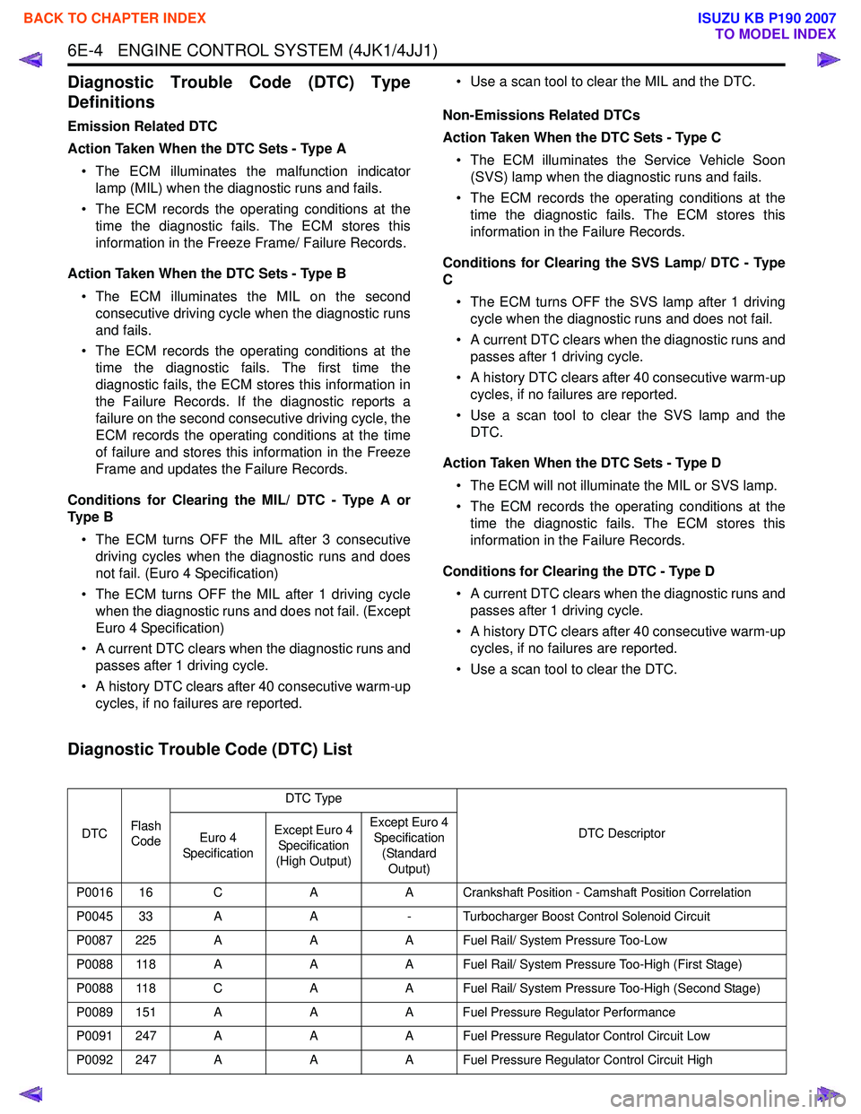
Diagnostic Trouble Code (DTC) List
DTC Flash
Code DTC Type
DTC Descriptor
Euro 4
Specification Except Euro 4
Specification
(High Output) Except Euro 4
Specification
(Standard Output)
P0016 16 C AA Crankshaft Position - Camshaft Position Correlation
P0045 33 A A- Turbocharger Boost Control Solenoid Circuit
P0087 225 A AA Fuel Rail/ System Pressure Too-Low
P0088 118 A AA Fuel Rail/ System Pressure Too-High (First Stage)
P0088 118 C AA Fuel Rail/ System Pressure Too-High (Second Stage)
P0089 151 A AA Fuel Pressure Regulator Performance
P0091 247 A AA Fuel Pressure Regulator Control Circuit Low
P0092 247 A AA Fuel Pressure Regulator Control Circuit High
BACK TO CHAPTER INDEX
TO MODEL INDEX
ISUZU KB P190 2007
Page 1662 of 6020
ENGINE CONTROL SYSTEM (4JK1/4JJ1) 6E-45
Diagnostic System Check - Engine Controls
Description
The Diagnostic System Check - Engine Controls is an
organized approach to identifying a condition that is
created by a malfunction in the electronic engine
control system. The Diagnostic System Check must be
the starting point for any driveability concern. The
Diagnostic System Check directs the service technician
to the next logical step in order to diagnose the
concern. Understanding and correctly using the
diagnostic table reduces diagnostic time, and prevents
the replacement of good parts.
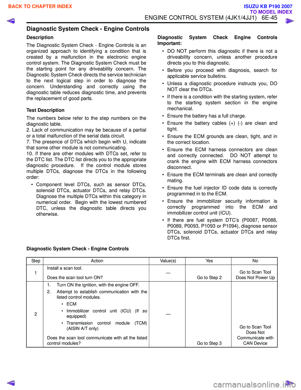
Test Description
The numbers below refer to the step numbers on the
diagnostic table.
2. Lack of communication may be because of a partial
or a total malfunction of the serial data circuit.
7. The presence of DTCs which begin with U, indicate
that some other module is not communicating.
10. If there are other modules with DTCs set, refer to
the DTC list. The DTC list directs you to the appropriate
diagnostic procedure. If the control module stores
multiple DTCs, diagnose the DTCs in the following
order:
• Component level DTCs, such as sensor DTCs, solenoid DTCs, actuator DTCs, and relay DTCs.
Diagnose the multiple DTCs within this category in
numerical order. Begin with the lowest numbered
DTC, unless the diagnostic table directs you
otherwise. Diagnostic System Check Engine Controls
Important:
• DO NOT perform this diagnostic if there is not a driveability concern, unless another procedure
directs you to this diagnostic.
• Before you proceed with diagnosis, search for applicable service bulletins.
• Unless a diagnostic procedure instructs you, DO NOT clear the DTCs.
• If there is a condition with the starting system, refer to the starting system section in the engine
mechanical.
• Ensure the battery has a full charge.
• Ensure the battery cables (+) (-) are clean and tight.
• Ensure the ECM grounds are clean, tight, and in the correct location.
• Ensure the ECM harness connectors are clean and correctly connected. DO NOT attempt to
crank the engine with ECM harness connectors
disconnect.
• Ensure the ECM terminals are clean and correctly mating.
• Ensure the fuel injector ID code data is correctly programmed in to the ECM.
• Ensure the immobilizer security information is correctly programmed into the ECM and
immobilizer control unit (ICU).
• If there are fuel system DTC’s (P0087, P0088, P0089, P0093, P1093 or P1094), diagnose sensor
DTCs, solenoid DTCs, actuator DTCs and relay
DTCs first.
Diagnostic System Check - Engine Controls
Step Action Value(s)Yes No
1 Install a scan tool.
Does the scan tool turn ON? —
Go to Step 2 Go to Scan Tool
Does Not Power Up
2 1. Turn ON the ignition, with the engine OFF.
2. Attempt to establish communication with the listed control modules.
•ECM
• Immobilizer control unit (ICU) (If so equipped)
• Transmission control module (TCM) (AISIN A/T only)
Does the scan tool communicate with all the listed
control modules? —
Go to Step 3 Go to Scan Tool
Does Not
Communicate with CAN Device
BACK TO CHAPTER INDEX
TO MODEL INDEX
ISUZU KB P190 2007
Page 1667 of 6020
6E-50 ENGINE CONTROL SYSTEM (4JK1/4JJ1)
Scan Tool Data Definitions
This information will assist in emission or driveability
problems. The displays can be viewed while the vehicle
is being driven. Always perform the Diagnostic System
Check - Engine Controls first. The Diagnostic System
Check will confirm proper system operation.
Engine Speed
This parameter displays the rotational speed of the
crankshaft as calculated by the ECM based on inputs
from the crankshaft position (CKP) sensor or camshaft
position (CMP) sensor.
Desired Idle Speed
This parameter displays the idle speed requested by
the ECM. The ECM will change desired idle speed
based on engine coolant temperature and other inputs.
Calculate Engine Load
This parameter displays the engine load in percent
based on inputs to the ECM from various engine
sensors. The scan tool will display a lower percentage
when the engine is at idle with little or no load. The
scan tool will display a higher percentage when the
engine is running at high engine speed under a heavy
load.
Coolant Temperature
This parameter displays the temperature of the engine
coolant as calculated by the ECM using the signal from
the engine coolant temperature (ECT) sensor. The
scan tool will display a low temperature when the ECT
sensor signal voltage is high, and a high temperature
when the ECT sensor signal voltage is low.
Engine Coolant Temperature Sensor
This parameter displays the voltage signal sent to the
ECM from the engine coolant temperature (ECT)
sensor. ECT sensor is a range of value indicating a low
voltage when the temperature is high, and a high
voltage when the temperature is low.
Intake Air Temperature
This parameter displays the temperature of the intake
air as calculated by the ECM using the signal from the
intake air temperature (IAT) sensor. The scan tool will
display a low temperature when the IAT sensor signal
voltage is high, and a high temperature when the IAT
sensor signal voltage is low. Intake Air Temperature Sensor
This parameter displays the voltage signal sent to the
ECM from the intake air temperature (IAT) sensor. IAT
sensor is a range of value indicating a low voltage
when the temperature is high, and a high voltage when
the temperature is low.
Fuel Temperature
This parameter displays the temperature of the fuel as
calculated by the ECM using the signal from the fuel
temperature (FT) sensor. The scan tool will display a
low temperature when the FT sensor signal voltage is
high, and a high temperature when the FT sensor
signal voltage is low.
Fuel Temperature Sensor
This parameter displays the voltage signal sent to the
ECM from the fuel temperature (FT) sensor. FT sensor
is a range of value indicating a low voltage when the
temperature is high, and a high voltage when the
temperature is low.
MAF (Mass Air Flow)
This parameter displays the air flow into the engine as
calculated by the ECM based on the mass air flow
(MAF) sensor input. The scan tool will display a high
value at higher engine speeds, and a low value at lower
engine speed.
MAF Sensor (Mass Air Flow)
This parameter displays the voltage signal sent to the
ECM from the mass air flow (MAF) sensor. MAF sensor
is a range of value indicating a low voltage at lower
engine speed, and a high voltage at a higher engine
speeds.
Barometric Pressure
This parameter displays the barometric pressure
(BARO) as calculated by the ECM using the signal from
the BARO sensor. The scan tool will display a low
barometric pressure in high altitude area.
Barometric Pressure Sensor
This parameter displays the voltage signal sent to the
ECM from the barometric pressure (BARO) sensor.
BARO sensor is a range of value indicating a low
voltage in high altitude area, and a middle voltage in
sea level.
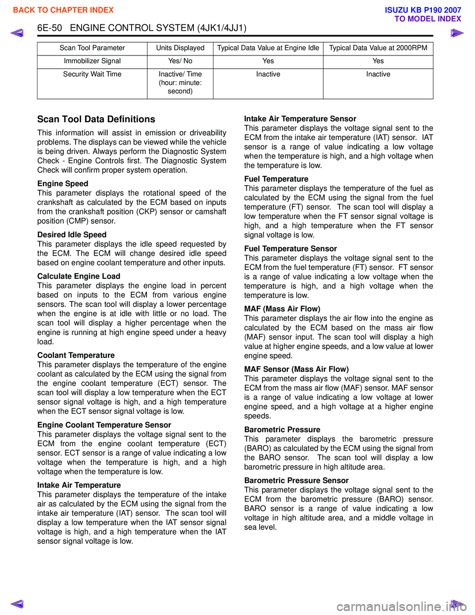
Immobilizer Signal Yes/ NoYes Yes
Security Wait Time Inactive/ Time
(hour: minute: second) Inactive
Inactive
Scan Tool Parameter Units Displayed Typical Data Value at Engine Idle Typical Data Value at 2000RPM
BACK TO CHAPTER INDEX
TO MODEL INDEX
ISUZU KB P190 2007