2007 ISUZU KB P190 ECU
[x] Cancel search: ECUPage 1273 of 6020
Engine Control System (4JH1) 6E-239
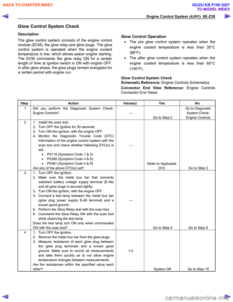
Glow Control System Check
Description
The glow control system consists of the engine control
module (ECM), the glow relay and glow plugs. The glo
w
control system is operated when the engine coolant
temperature is low, which allows easier engine starting.
The ECM commands the glow relay ON for a certain
length of time at ignition switch is ON with engine OFF.
In after glow phase, the glow plugs remain energized fo
r
a certain period with engine run.
Glow Control Operation
•
The pre glow control system operates when the
engine coolant temperature is less than 30 °C
(86 °F).
• The after glow control system operates when the
engine coolant temperature is less than 60 °C
(140 °F).
Glow Control System Check
Schematic Reference: Engine Controls Schematics
Connector End View Reference: Engine Controls
Connector End Views
Step Action Value(s) Yes No
1 Did you perform the Diagnostic System Check-
Engine Controls?
Go to Step 2 Go to Diagnostic
System Check-
Engine Controls
2 1. Install the scan tool. 2. Turn OFF the ignition for 30 seconds.
3. Turn ON the ignition, with the engine OFF.
4. Monitor the Diagnostic Trouble Code (DTC) Information of the engine control system with the
scan tool and check whether following DTC(s) is
set: • P0115 (Symptom Code 1 & 2)
• P0380 (Symptom Code 4 & 8)
• P0381 (Symptom Code 4 & 8)
Are any of the above DTC(s) set?
Refer to Applicable DTC Go to Step 3
3 1. Turn OFF the ignition.
2. Make sure the metal bus bar that connects switched battery voltage supply terminal (E-49)
and all glow plugs is secured tightly.
3. Turn ON the ignition, with the engine OFF
4. Connect a test lamp between the metal bus bar (glow plug power supply E-49 terminal) and a
known good ground.
5. Perform the Glow Relay test with the scan tool.
6. Command the Glow Relay ON with the scan tool while observing the test lamp.
Does the test lamp turn ON only when commanded
ON with the scan tool?
Go to Step 4 Go to Step 5
4 1. Turn OFF the ignition. 2. Remove the metal bus bar from the glow plugs.
3. Measure resistance of each glow plug between the glow plug terminals and a known good
ground. Make sure to record all measurements
and take them quickly as to not allow engine
temperature changes between measurements.
Are the resistances within the specified value each
other? 1
Ω
System OK Go to Step 15
BACK TO CHAPTER INDEX
TO MODEL INDEX
ISUZU KB P190 2007
Page 1310 of 6020
6E-276 Engine Control System (4JH1)
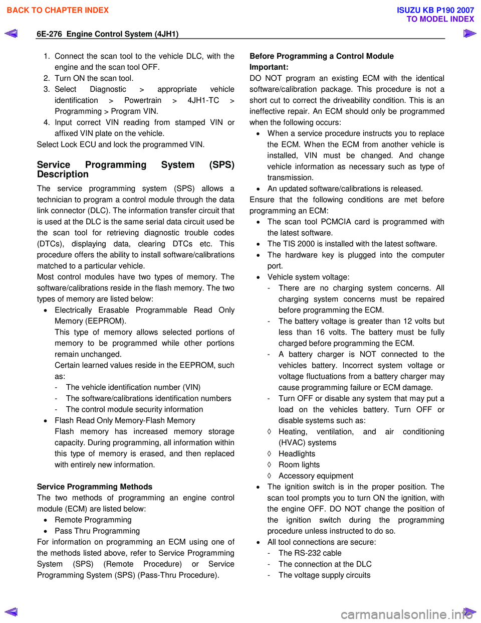
1. Connect the scan tool to the vehicle DLC, with theengine and the scan tool OFF.
2. Turn ON the scan tool.
3. Select Diagnostic > appropriate vehicle identification > Powertrain > 4JH1-TC >
Programming > Program VIN.
4. Input correct VIN reading from stamped VIN o
r
affixed VIN plate on the vehicle.
Select Lock ECU and lock the programmed VIN.
Service Programming System (SPS)
Description
The service programming system (SPS) allows a
technician to program a control module through the data
link connector (DLC). The information transfer circuit that
is used at the DLC is the same serial data circuit used be
the scan tool for retrieving diagnostic trouble codes
(DTCs), displaying data, clearing DTCs etc. This
procedure offers the ability to install software/calibrations
matched to a particular vehicle.
Most control modules have two types of memory. The
software/calibrations reside in the flash memory. The two
types of memory are listed below: • Electrically Erasable Programmable Read Onl
y
Memory (EEPROM).
This type of memory allows selected portions o
f
memory to be programmed while other portions
remain unchanged.
Certain learned values reside in the EEPROM, such as:
- The vehicle identification number (VIN)
- The software/calibrations identification numbers
- The control module security information
• Flash Read Only Memory-Flash Memory
Flash memory has increased memory storage capacity. During programming, all information within
this type of memory is erased, and then replaced
with entirely new information.
Service Programming Methods
The two methods of programming an engine control
module (ECM) are listed below: • Remote Programming
• Pass Thru Programming
For information on programming an ECM using one o
f
the methods listed above, refer to Service Programming
System (SPS) (Remote Procedure) or Service
Programming System (SPS) (Pass-Thru Procedure).
Before Programming a Control Module
Important:
DO NOT program an existing ECM with the identical
software/calibration package. This procedure is not a
short cut to correct the driveability condition. This is an
ineffective repair. An ECM should only be programmed
when the following occurs: • W hen a service procedure instructs you to replace
the ECM. W hen the ECM from another vehicle is
installed, VIN must be changed. And change
vehicle information as necessary such as type o
f
transmission.
• An updated software/calibrations is released.
Ensure that the following conditions are met before
programming an ECM: • The scan tool PCMCIA card is programmed with
the latest software.
• The TIS 2000 is installed with the latest software.
• The hardware key is plugged into the compute
r
port.
• Vehicle system voltage:
- There are no charging system concerns. All charging system concerns must be repaired
before programming the ECM.
- The battery voltage is greater than 12 volts bu
t
less than 16 volts. The battery must be fully
charged before programming the ECM.
-
A battery charger is NOT connected to the
vehicles battery. Incorrect system voltage o
r
voltage fluctuations from a battery charger may
cause programming failure or ECM damage.
- Turn OFF or disable any system that may put a load on the vehicles battery. Turn OFF o
r
disable systems such as:
◊ Heating, ventilation, and air conditioning
(HVAC) systems
◊ Headlights
◊ Room lights
◊ Accessory equipment
• The ignition switch is in the proper position. The
scan tool prompts you to turn ON the ignition, with
the engine OFF. DO NOT change the position o
f
the ignition switch during the programming
procedure unless instructed to do so.
• All tool connections are secure:
- The RS-232 cable
- The connection at the DLC
- The voltage supply circuits
BACK TO CHAPTER INDEX
TO MODEL INDEX
ISUZU KB P190 2007
Page 1311 of 6020
Engine Control System (4JH1) 6E-277
• DO NOT disturb the tool harnesses while
programming. If an interruption occurs during the
programming procedure, programming failure o
r
ECM damage may occur.
• If you are performing the Pass-Thru programming
procedure using a notebook computer without the
power cord, ensure that the internal battery is full
y
charged.
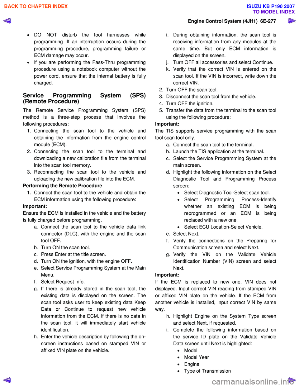
Service Programming System (SPS)
(Remote Procedure)
The Remote Service Programming System (SPS)
method is a three-step process that involves the
following procedures: 1. Connecting the scan tool to the vehicle and obtaining the information from the engine control
module (ECM).
2. Connecting the scan tool to the terminal and downloading a new calibration file from the terminal
into the scan tool memory.
3. Reconnecting the scan tool to the vehicle and uploading the new calibration file into the ECM.
Performing the Remote Procedure 1. Connect the scan tool to the vehicle and obtain the ECM information using the following procedure:
Important:
Ensure the ECM is installed in the vehicle and the batter
y
is fully charged before programming. a. Connect the scan tool to the vehicle data linkconnector (DLC), with the engine and the scan
tool OFF.
b. Turn ON the scan tool.
c. Press Enter at the title screen.
d. Turn ON the ignition, with the engine OFF.
e. Select Service Programming System at the Main Menu.
f. Select Request Info.
g. If there is already stored in the scan tool, the existing data is displayed on the screen. The
scan tool asks user to keep existing data Keep
Data or Continue to request new vehicle
information from the ECM. If there is no data in
the scan tool, it will immediately start vehicle
identification.
h. Enter the vehicle description by following the on- screen instructions based on stamped VIN o
r
affixed VIN plate on the vehicle.
i. During obtaining information, the scan tool is
receiving information from any modules at the
same time. But only ECM information is
displayed on the screen.
j. Turn OFF all accessories and select Continue.
k. Verify that the correct VIN is entered on the scan tool. If the VIN is incorrect, write down the
correct VIN.
2. Turn OFF the scan tool.
3. Disconnect the scan tool from the vehicle.
4. Turn OFF the ignition.
5. Transfer the data from the terminal to the scan tool using the following procedure:
Important:
The TIS supports service programming with the scan
tool scan tool only. a. Connect the scan tool to the terminal.
b. Launch the TIS application at the terminal.
c. Select the Service Programming System at the main screen.
d. Highlight the following information on the Selec
t
Diagnostic Tool and Programming Process
screen: • Select Diagnostic Tool-Select scan tool.
• Select Programming Process-Identif
y
whether an existing ECM is being
reprogrammed or an ECM is being
replaced with a new one.
• Select ECU Location-Select Vehicle.
e. Select Next.
f. Verify the connections on the Preparing fo
r
Communication screen and select Next.
g. Verify the VIN on the Validate Vehicle Identification Number (VIN) screen and selec
t
Next.
Important:
If the ECM is replaced to new one, VIN does no
t
displayed. Input correct VIN reading from stamped VIN
or affixed VIN plate on the vehicle. If the ECM from
another vehicle is installed, input correct VIN by same
way.
h. Highlight Engine on the System Type screen and select Next, if requested.
i. Complete the following information based on the service ID plate on the Validate Vehicle
Data screen until Next is highlighted: • Model
• Model Year
• Engine
• Type of Transmission
BACK TO CHAPTER INDEX
TO MODEL INDEX
ISUZU KB P190 2007
Page 1312 of 6020
6E-278 Engine Control System (4JH1)
• Destination Code
j. Select Next.
k. Verify your selection on the Summary screen.
Important:
Refer to Service Bulletins before service programming is
performed if the bulletins are listed along with the
calibration files.
Important:
Select Cancel if you receive a message stating that the
calibration selected is already the current calibration in
the ECM and reprogramming with the same download is
not allowed.
l. Select Reprog.
m. The Transfer Data screen will appear until the progress bar reaches 100%.
6. Close the application and return to the TIS application selection screen after the download is
complete.
7. Turn OFF the scan tool.
8. Disconnect the scan tool from the terminal.
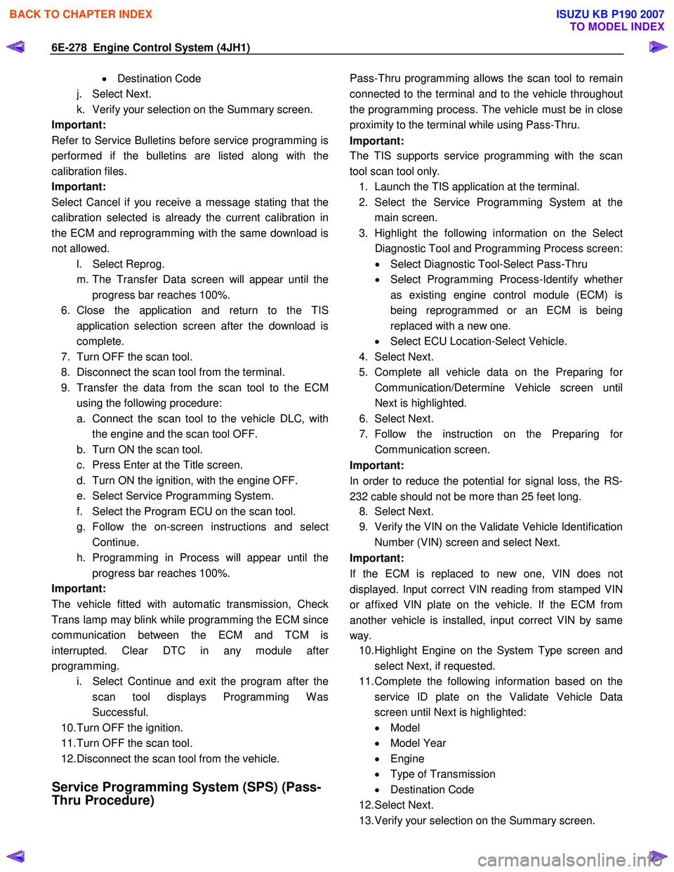
9. Transfer the data from the scan tool to the ECM using the following procedure:
a. Connect the scan tool to the vehicle DLC, with the engine and the scan tool OFF.
b. Turn ON the scan tool.
c. Press Enter at the Title screen.
d. Turn ON the ignition, with the engine OFF.
e. Select Service Programming System.
f. Select the Program ECU on the scan tool.
g. Follow the on-screen instructions and select Continue.
h. Programming in Process will appear until the progress bar reaches 100%.
Important:
The vehicle fitted with automatic transmission, Check
Trans lamp may blink while programming the ECM since
communication between the ECM and TCM is
interrupted. Clear DTC in any module afte
r
programming.
i. Select Continue and exit the program after the scan tool displays Programming W as
Successful.
10. Turn OFF the ignition.
11. Turn OFF the scan tool.
12. Disconnect the scan tool from the vehicle.
Service Programming System (SPS) (Pass-
Thru Procedure)
Pass-Thru programming allows the scan tool to remain
connected to the terminal and to the vehicle throughou
t
the programming process. The vehicle must be in close
proximity to the terminal while using Pass-Thru.
Important:
The TIS supports service programming with the scan
tool scan tool only.
1. Launch the TIS application at the terminal.
2. Select the Service Programming System at the main screen.
3. Highlight the following information on the Selec
t
Diagnostic Tool and Programming Process screen:
• Select Diagnostic Tool-Select Pass-Thru
• Select Programming Process-Identify whethe
r
as existing engine control module (ECM) is
being reprogrammed or an ECM is being
replaced with a new one.
• Select ECU Location-Select Vehicle.
4. Select Next.
5. Complete all vehicle data on the Preparing fo
r
Communication/Determine Vehicle screen until
Next is highlighted.
6. Select Next.
7. Follow the instruction on the Preparing fo
r
Communication screen.
Important:
In order to reduce the potential for signal loss, the RS-
232 cable should not be more than 25 feet long.
8. Select Next.
9. Verify the VIN on the Validate Vehicle Identification Number (VIN) screen and select Next.
Important:
If the ECM is replaced to new one, VIN does no
t
displayed. Input correct VIN reading from stamped VIN
or affixed VIN plate on the vehicle. If the ECM from
another vehicle is installed, input correct VIN by same
way. 10. Highlight Engine on the System Type screen and
select Next, if requested.
11. Complete the following information based on the service ID plate on the Validate Vehicle Data
screen until Next is highlighted:
• Model
• Model Year
• Engine
• Type of Transmission
• Destination Code
12. Select Next.
13. Verify your selection on the Summary screen.
BACK TO CHAPTER INDEX
TO MODEL INDEX
ISUZU KB P190 2007
Page 1332 of 6020
6E-298 Engine Control System (4JH1)
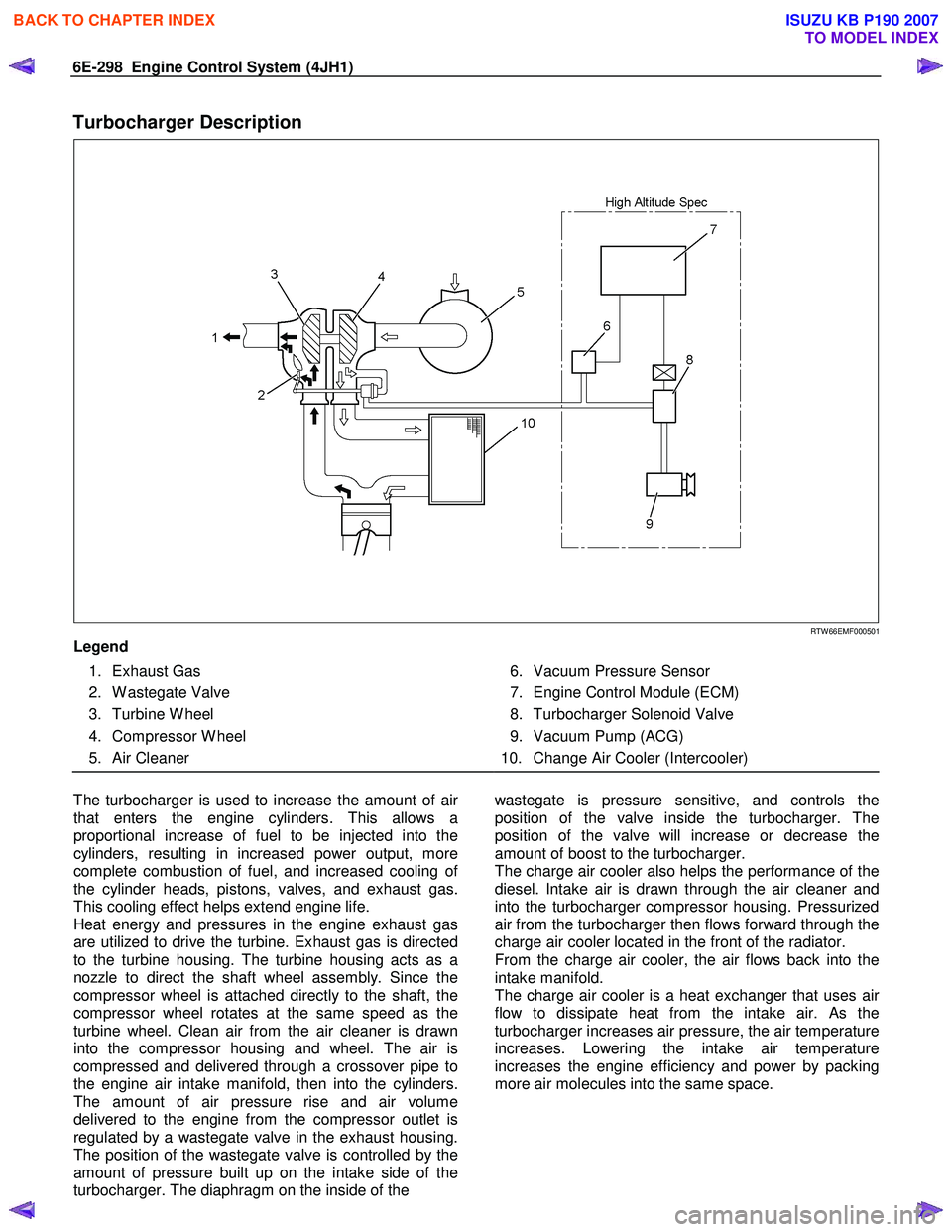
Turbocharger Description
RTW 66EMF000501
Legend
1. Exhaust Gas
2. W astegate Valve
3. Turbine W heel
4. Compressor W heel
5. Air Cleaner
6. Vacuum Pressure Sensor
7. Engine Control Module (ECM)
8. Turbocharger Solenoid Valve
9. Vacuum Pump (ACG)
10. Change Air Cooler (Intercooler)
The turbocharger is used to increase the amount of ai
r
that enters the engine cylinders. This allows a
proportional increase of fuel to be injected into the
cylinders, resulting in increased power output, more
complete combustion of fuel, and increased cooling o
f
the cylinder heads, pistons, valves, and exhaust gas.
This cooling effect helps extend engine life.
Heat energy and pressures in the engine exhaust gas
are utilized to drive the turbine. Exhaust gas is directed
to the turbine housing. The turbine housing acts as a
nozzle to direct the shaft wheel assembly. Since the
compressor wheel is attached directly to the shaft, the
compressor wheel rotates at the same speed as the
turbine wheel. Clean air from the air cleaner is drawn
into the compressor housing and wheel. The air is
compressed and delivered through a crossover pipe to
the engine air intake manifold, then into the cylinders.
The amount of air pressure rise and air volume
delivered to the engine from the compressor outlet is
regulated by a wastegate valve in the exhaust housing.
The position of the wastegate valve is controlled by the
amount of pressure built up on the intake side of the
turbocharger. The diaphragm on the inside of the
wastegate is pressure sensitive, and controls the
position of the valve inside the turbocharger. The
position of the valve will increase or decrease the
amount of boost to the turbocharger.
The charge air cooler also helps the performance of the
diesel. Intake air is drawn through the air cleaner and
into the turbocharger compressor housing. Pressurized
air from the turbocharger then flows forward through the
charge air cooler located in the front of the radiator.
From the charge air cooler, the air flows back into the
intake manifold.
The charge air cooler is a heat exchanger that uses ai
r
flow to dissipate heat from the intake air. As the
turbocharger increases air pressure, the air temperature
increases. Lowering the intake air temperature
increases the engine efficiency and power by packing
more air molecules into the same space.
BACK TO CHAPTER INDEX
TO MODEL INDEX
ISUZU KB P190 2007
Page 1539 of 6020
6B-16 ENGINE COOLING (4JK1/4JJ1)
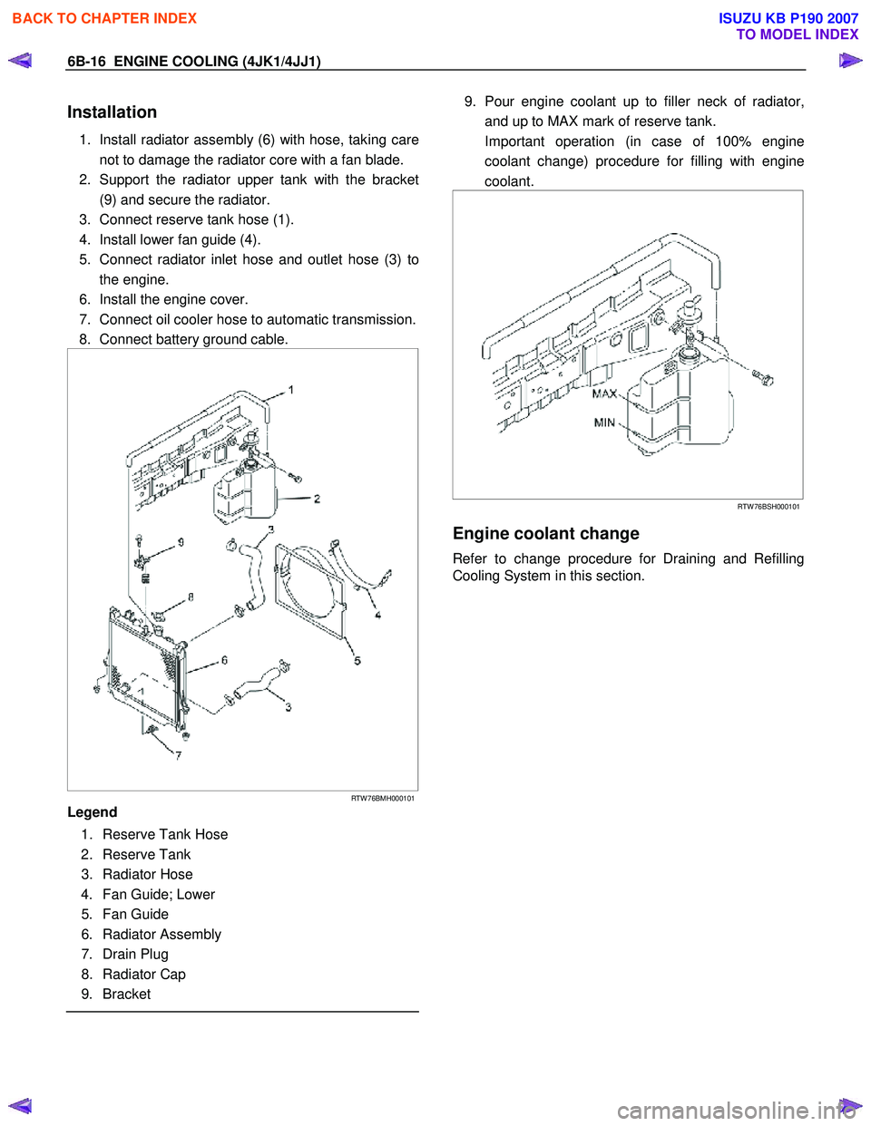
Installation
1. Install radiator assembly (6) with hose, taking care
not to damage the radiator core with a fan blade.
2. Support the radiator upper tank with the bracket (9) and secure the radiator.
3. Connect reserve tank hose (1).
4. Install lower fan guide (4).
5. Connect radiator inlet hose and outlet hose (3) to the engine.
6. Install the engine cover.
7. Connect oil cooler hose to automatic transmission.
8. Connect battery ground cable.
RTW 76BMH000101
Legend
1. Reserve Tank Hose
2. Reserve Tank
3. Radiator Hose
4. Fan Guide; Lower
5. Fan Guide
6. Radiator Assembly
7. Drain Plug
8. Radiator Cap
9. Bracket
9. Pour engine coolant up to filler neck of radiator,
and up to MAX mark of reserve tank.
Important operation (in case of 100% engine coolant change) procedure for filling with engine
coolant.
RTW 76BSH000101
Engine coolant change
Refer to change procedure for Draining and Refilling
Cooling System in this section.
BACK TO CHAPTER INDEX
TO MODEL INDEX
ISUZU KB P190 2007
Page 1551 of 6020
6C-10 FUEL SYSTEM (4JK1/4JJ1)
Fuel System Check
Description
Conforms to a fuel leak. Engine acceleration raises fuel
pressure and which increases the leak.
Leak could be in the following pipes and locations.
• Between injectors and fuel rail.
• Between fuel rail and fuel supply pump.
• Between fuel supply pump and fuel filter.
• Between fuel filter and fuel tank.
• Between pressure limiter and fuel cooler.
• Between fuel cooler and fuel tank.
• Between injector over flow and leak off pipe.
Diagnostic Aids
Check the following items.
• Air in the fuel line
• Clogged fuel filter
• Fuel pipe malfunction (Crushing, breakage,
clogging, disconnection, etc.)
• Fuel cooler malfunction (Crushing, breakage,
clogging, disconnection, etc.)
• Fuel tank malfunction
• Injector malfunction
• Fuel supply pump malfunction
• Pressure limiter malfunction
An intermittent may be caused by a poor connection,
rubbed-through wire insulation or a wire broken inside
the insulation. Check for poor connections or a
damaged harness.
Inspect the ECM harness and connector for imprope
r
mating, broken locks, improperly formed or damaged
terminals, poor terminal-to-wire connection, and
damaged harness.
ECU may set a DTC, if there is adequate air in fuel line.
Schematic Reference: Engine Controls Schematics
Step Action Value(s) Yes No
1 Check the fuel quantity. W as a problem found?
Go to Step 2 Add fuel and
Go to Step 2
2 Check the fuel quality.
1. Discharge the fuel from fuel tank
2. Replenish the tank with specified fuel
3. Bleed the air from the fuel system
4. Start the engine
Could the engine be started?
Go to Step 7 Go to Step 3
3 Bleed the air from fuel system. Refer to Fuel
System Air Bleeding in this section.
Is the action complete?
Go to Step 4
4 Check the main fuel filter for clogging.
Clean, repair, or replace as required.
Notice: Replacement of a fuel filter is checking
to a dealer.
Is the action complete?
Go to Step 5
5 Check the fuel line and fuel cooler for damage
and leakage.
Clean, repair, or replace as required.
• Crushed areas
• Breakage
• Cracks
• Loose connections
Is the action complete?
Go to Step 6
BACK TO CHAPTER INDEX
TO MODEL INDEX
ISUZU KB P190 2007
Page 1558 of 6020
FUEL SYSTEM (4JK1/4JJ1) 6C-17
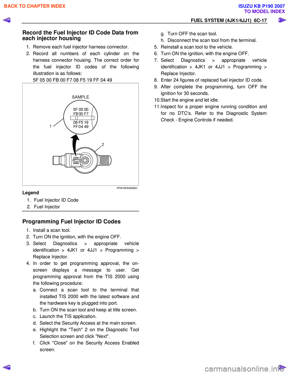
Record the Fuel Injector ID Code Data from
each injector housing
1. Remove each fuel injector harness connector.
2. Record all numbers of each cylinder on the harness connector housing. The correct order fo
r
the fuel injector ID codes of the following
illustration is as follows:
5F 05 00 FB 00 F7 08 F5 19 FF 04 49
RTW 76ESH002601
Legend
1. Fuel Injector ID Code
2. Fuel Injector
Programming Fuel Injector ID Codes
1. Install a scan tool.
2. Turn ON the ignition, with the engine OFF.
3. Select Diagnostics > appropriate vehicle identification > 4JK1 or 4JJ1 > Programming >
Replace Injector.
4. In order to get programming approval, the on- screen displays a message to user. Get
programming approval from the TIS 2000 using
the following procedure:
a. Connect a scan tool to the terminal that installed TIS 2000 with the latest software and
the hardware key is plugged into port.
b. Turn ON the scan tool and keep at title screen.
c. Launch the TIS application.
d. Select the Security Access at the main screen.
e. Highlight the "Tech" 2 on the Diagnostic Tool Selection screen and click "Next".
f. Click "Close" on the Security Access Enabled screen.
g. Turn OFF the scan tool.
h. Disconnect the scan tool from the terminal.
5. Reinstall a scan tool to the vehicle.
6. Turn ON the ignition, with the engine OFF.
7. Select Diagnostics > appropriate vehicle identification > 4JK1 or 4JJ1 > Programming >
Replace Injector.
8. Enter 24 figures of replaced fuel injector ID code.
9.
After complete the programming, turn OFF the
ignition for 30 seconds.
10.Start the engine and let idle.
11.Inspect for a proper engine running condition and for no DTC's. Refer to the Diagnostic System
Check - Engine Controls if needed.
BACK TO CHAPTER INDEX
TO MODEL INDEX
ISUZU KB P190 2007