Page 4554 of 6020
UNIT REPAIR (JR405E) 7A4-77
30ASSY067
•
Apply ATF to the O-ring at the outside of the oil pump.
• Install the oil pump assembly to the transmission case.
•
Apply sealing agent (TB1215) to the threaded surfaces
of the 8 fixing bolts and tighten to the specified torque.
Torque: 58 N ⋅
⋅⋅
⋅
m (5.9 kgf ⋅
⋅⋅
⋅
m/43 Ib ⋅
⋅⋅
⋅
ft)
31ASSY068
14.O-ring
Install a new O-ring to the input shaft.
32ASSY116
15.Converter housing
Install the converter housing and tighten the bolts to the
specified torque. Torque: 53 N ⋅
⋅⋅
⋅
m (5.4 kgf ⋅
⋅⋅
⋅
m/39 Ib ⋅
⋅⋅
⋅
ft)
33ASSY075
16.Actuator support
Install the actuator support.
34ASSY077
17.Parking pawl, shaft, spring, and spacer
Install the parking pawl, the shaft, the spring, and the
spacer.
BACK TO CHAPTER INDEX
TO MODEL INDEX
ISUZU KB P190 2007
Page 4556 of 6020
UNIT REPAIR (JR405E) 7A4-79
40ASSY091
•
Push the output shaft into place.
19.Rear extension (2WD) or adapter case (4WD)
• Use the oil seal installer to install the oil seal to the rea
r
extension (2W D) or adapter case (4W D).
Oil seal installer:
5-8840-2769-0 (2WD)
5-8840-2770-0 (4WD)
41ASSY096
•
Install the bearing (with bearing race) to the rear
extension (2W D) or adapter case (4W D).
NOTE:
•
••
•
The black side (bearing race) of the bearing must be
visible.
•
••
•
Apply Vaseline to the bearing.
249L300005
•
Apply sealing agent (TB1216B) to the rear extension
(2W D) or adapter case (4W D) contact surfaces.
249L300006
• Install the rear extension (2W D) or adapter case (4W D)
to the transmission case and tighten the 10 bolts to the
specified torque.
Torque: 53 N ⋅
⋅⋅
⋅
m (5.4 kgf ⋅
⋅⋅
⋅
m/39 Ib ⋅
⋅⋅
⋅
ft)
BACK TO CHAPTER INDEX
TO MODEL INDEX
ISUZU KB P190 2007
Page 4558 of 6020
UNIT REPAIR (JR405E) 7A4-81
244L300001
21.Oil pan
• Install a new gasket and the oil pan.
• Tighten the bolts to the specified torque.
Torque: 8 N ⋅
⋅⋅
⋅
m (0.8 kgf ⋅
⋅⋅
⋅
m/69 lb ⋅
⋅⋅
⋅
in)
47INH-SW 01
22.Inhibitor switch
• Secure the inhibitor switch (1) by hand-tightening the 2
bolts.
• Use the inhibitor switch set plate to align the neutral
holes (manual shaft and inhibitor switch).
Turn the inhibitor switch to adjust it.
Inhibitor switch set plate: 5-8840-2763-0
NOTE:
Inhibitor switch adjustment is very important.
If the inhibitor switch is not correctly adjusted, the
automatic transmission will not function normally.
• Tighten the 2 inhibitor switch bolts to the specified
torque.
BACK TO CHAPTER INDEX
TO MODEL INDEX
ISUZU KB P190 2007
Page 4560 of 6020

UNIT REPAIR (JR405E) 7A4-83
SERVICE STANDARD
Name BESCO ATF III ATF
Quantity L (US gal/Imp gal) 9.2 – 9.6 (2.43-2.54/2.02-2.11)
Seal ring clearance mm (in) 0.10 – 0.25 (0.0039 – 0.0098)
Housing and inner rotor side clearance mm (in) 0.02 – 0.04 (0.0008 – 0.0016)
Oil pump
Outer rotor and crescent clearance mm (in) 0.02 – 0.15 (0.0008 – 0.0059)
Number of drive plates / driven plates 7/7
Standard mm (in) 2.0 (0.079)Drive plate facing thickness
Limit mm (in) 1.8 (0.071)
Retaining plate and snap ring clearance mm (in) 0.9 – 1.3 (0.035 – 0.051)
3.8 (0.150)
4.0 (0.157)
4.2 (0.165)
4.4 (0.173)
4.6 (0.181)
Available low clutch retaining plate thickness mm (in)
4.8 (0.189)
Number of coils 9.9
Outside diameter mm (in) 9.7 (0.382)
Free length mm (in) 36.4 (1.433)
Low clutch
Return spring Linear diameter mm (in) 1.2 (0.047)
Number of drive plates / driven plates 5/5
Standard mm (in) 2.0 (0.079)Drive plate facing thickness
Limit mm (in) 1.8 (0.071)
Retaining plate and snap ring clearance mm (in) 1.2 – 1.6 (0.047 – 0.063)
4.6 (0.181)
4.8 (0.189)
5.0 (0.197)
5.2 (0.205)
Available high clutch retaining plate thickness mm (in)
5.4 (0.213)
Number of coils 10.2
Outside diameter mm (in) 8.0 (0.315)
Free length mm (in) 27.1 (1.067)
High clutch
Return spring Linear diameter mm (in) 1.1 (0.043)
Number of drive plates / driven plates 2/2
Standard mm (in) 2.0 (0.079)Drive plate facing thickness
Limit mm (in) 1.8 (0.071)
Retaining plate and snap ring clearance mm (in) 0.6 – 0.9 (0.024 – 0.035)
4.8 (0.189)
5.0 (0.197)
5.2 (0.205)
Reverse clutch
Available reverse clutch retaining plate thickness mm (in) 5.4 (0.213)
Low one-way
clutch Seal ring clearance mm (in) 0.10 – 0.25 (0.0039 – 0.0098)
Number of drive plates / driven plates
6/6
Standard mm (in) 2.0 (0.079)Drive plate facing thickness
Limit mm (in) 1.8 (0.071)
Retaining plate and snap ring clearance mm (in) 0.7 – 1.1 (0.028 – 0.043)
5.2 (0.205)
5.4 (0.213)
5.6 (0.220)
5.8 (0.228)
Low & reverse
brake
Available low & reverse brake retaining plate
thickness mm (in)
6.0 (0.236)
BACK TO CHAPTER INDEX
TO MODEL INDEX
ISUZU KB P190 2007
Page 4561 of 6020

7A4-84 UNIT REPAIR (JR405E)
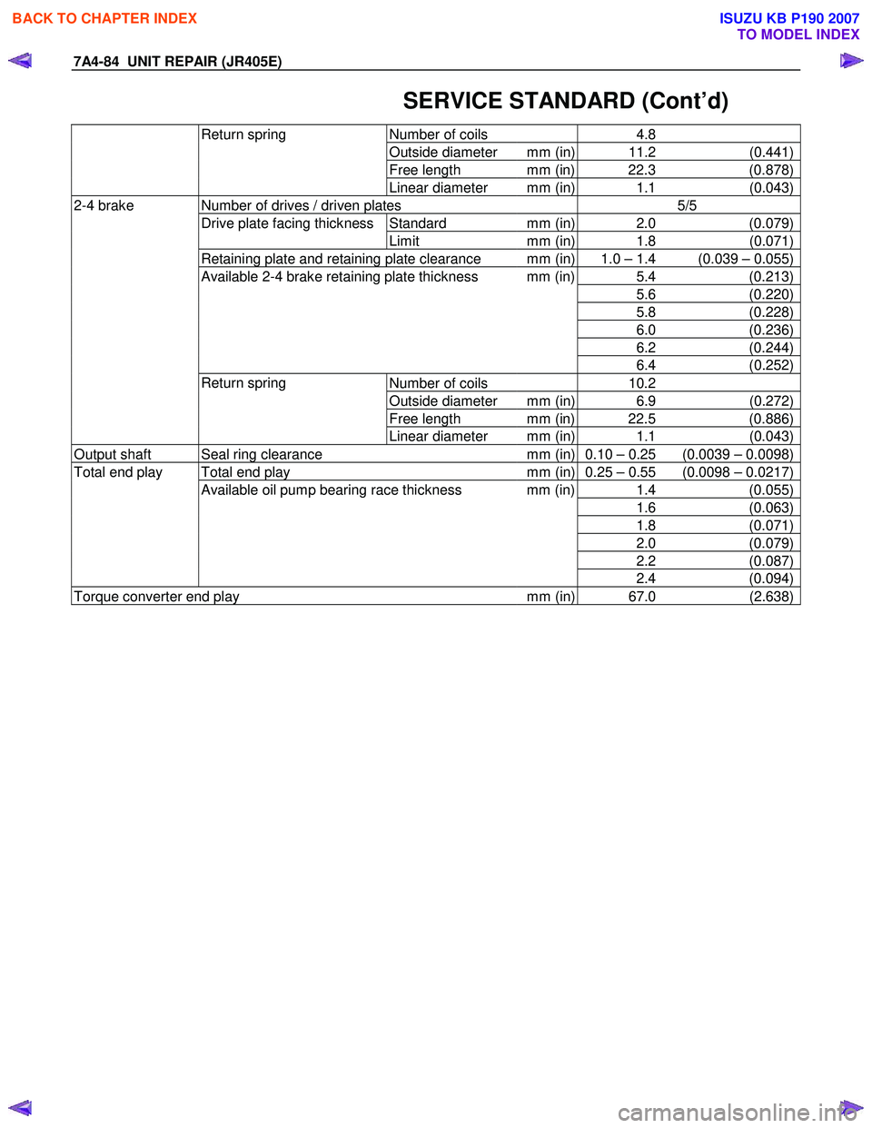
SERVICE STANDARD (Cont’d)
Number of coils 4.8
Outside diameter mm (in) 11.2 (0.441)
Free length mm (in) 22.3 (0.878)
Return spring
Linear diameter mm (in) 1.1 (0.043)
Number of drives / driven plates 5/5
Standard mm (in) 2.0 (0.079)Drive plate facing thickness
Limit mm (in) 1.8 (0.071)
Retaining plate and retaining plate clearance mm (in) 1.0 – 1.4 (0.039 – 0.055)
5.4 (0.213)
5.6 (0.220)
5.8 (0.228)
6.0 (0.236)
6.2 (0.244)
Available 2-4 brake retaining plate thickness mm (in)
6.4 (0.252)
Number of coils 10.2
Outside diameter mm (in) 6.9 (0.272)
Free length mm (in) 22.5 (0.886)
2-4 brake
Return spring Linear diameter mm (in) 1.1 (0.043)
Output shaft Seal ring clearance mm (in) 0.10 – 0.25 (0.0039 – 0.0098)
Total end play mm (in) 0.25 – 0.55 (0.0098 – 0.0217)
1.4 (0.055)
1.6 (0.063)
1.8 (0.071)
2.0 (0.079)
2.2 (0.087)
Total end play
Available oil pump bearing race thickness mm (in)
2.4 (0.094)
Torque converter end play mm (in) 67.0 (2.638)
BACK TO CHAPTER INDEX
TO MODEL INDEX
ISUZU KB P190 2007
Page 4562 of 6020
UNIT REPAIR (JR405E) 7A4-85
SPECIAL SERVICE TOOL
ILLUSTRATION PART NO. PART NAME
5-8841-0841-0
Holding Fixture
5-8840-0003-0
Holding Fixture Base
5-8840-2764-0
2-4 Brake Spring Compressor
5-8840-2767-0
High Clutch Spring Compressor
5-8840-2759-0
Low Clutch Spring Compressor
5-8840-2761-0
Oil Pump Oil Seal Installer
5-8840-2769-0
Rear Extension Oil Seal Installer
5-8840-2770-0
Rear Adapter Oil Seal Installer
5-8840-2758-0
Manual Shaft Oil Seal Installer
BACK TO CHAPTER INDEX
TO MODEL INDEX
ISUZU KB P190 2007
Page 4566 of 6020
7B-2 MSG MODEL
MAIN DATA AND SPECIFICATIONS
Transmission type Fully synchronized 5-forward gears with a constant
mesh type reverse gear.
Transmission Control Direct control with the gear shift lever on the floor.
Gear ratio MSG5K
1st : 4.122
2nd : 2.493
3rd : 1.504
4th : 1.000
5th : 0.855
Rev : 3.720
Oil capacity lit. (US gal.) 1.55(0.41)
W eight ; approx. kg(lbs) 33.3(73.8)
BACK TO CHAPTER INDEX
TO MODEL INDEX
ISUZU KB P190 2007
Page 4571 of 6020

MSG MODEL 7B-7
REMOVAL AND INSTALLATION
Read this Section carefully before performing any removal and installation procedure. This Section gives you
important points as well as the order of operation. Be sure that you understand everything in this Section before you
begin.
Important Operations - Removal
Battery Cable
Disconnect the negative (-) cable from the battery terminal.
Engine Hood
Apply setting marks to the engine hood and the engine hood
hinges before removing the engine hood.
Gear Shift Lever
1. Place the gear shift lever in the neutral position.
2. Remove the gear shift lever knob.
3. Remove the front console assembly.
4. Remove the gear shift lever grommet and dust cover.
5. Remove the gear shift lever cover bolts.
6. Remove the gear shift lever.
Note:
Cover the shift lever hole to prevent the entry of foreign
material into the transmission.
Lifting the Vehicle
1. Jack up the vehicle.
2. Place chassis stands at the front and the rear of the vehicle.
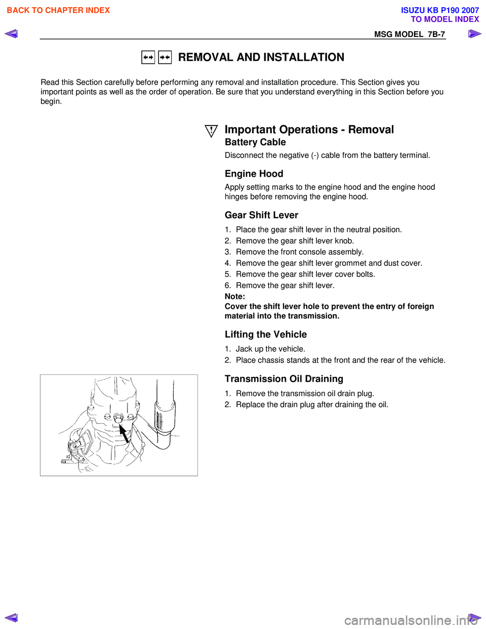
Transmission Oil Draining
1. Remove the transmission oil drain plug.
2. Replace the drain plug after draining the oil.
BACK TO CHAPTER INDEX
TO MODEL INDEX
ISUZU KB P190 2007