2007 ISUZU KB P190 check engine
[x] Cancel search: check enginePage 4245 of 6020
7A1-6 CONSTRUCTION AND FUNCTION
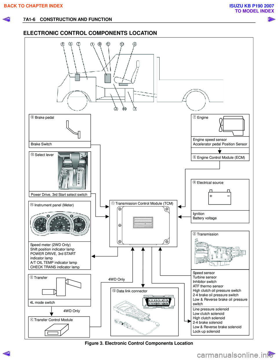
ELECTRONIC CONTROL COMPONENTS LOCATION
4WD Only 4W D Only
Instrument panel (Meter)
Speed meter (2WD Only)
Shift position indicator lamp
POWER DRIVE, 3rd START
indicator lamp
A/T OIL TEMP indicator lamp
CHECK TRANS indicator lam
p
Brake pedal
Brake Switch
Transmission Control Module (TCM)
Electrical source
Ignition
Battery voltage
Speed sensor
Turbine sensor
Inhibitor switch
ATF thermo sensor
High clutch oil pressure switch
2-4 brake oil pressure switch
Low & Reverse brake oil pressure
switch
Line pressure solenoid
Low clutch solenoid
High clutch solenoid
2-4 brake solenoid
Low & Reverse brake solenoid
Lock-up solenoid
Transmission
Transfer Control Module
Transfer
4L mode switch
Engine
Engine speed sensor
Accelerator pedal Position Sensor
Engine Control Module (ECM)
Data link connector
Select lever
Power Drive
, 3rd Start select switch
Figure 3. Electronic Control Components Location
BACK TO CHAPTER INDEX
TO MODEL INDEX
ISUZU KB P190 2007
Page 4264 of 6020
CONSTRUCTION AND FUNCTION 7A1-25
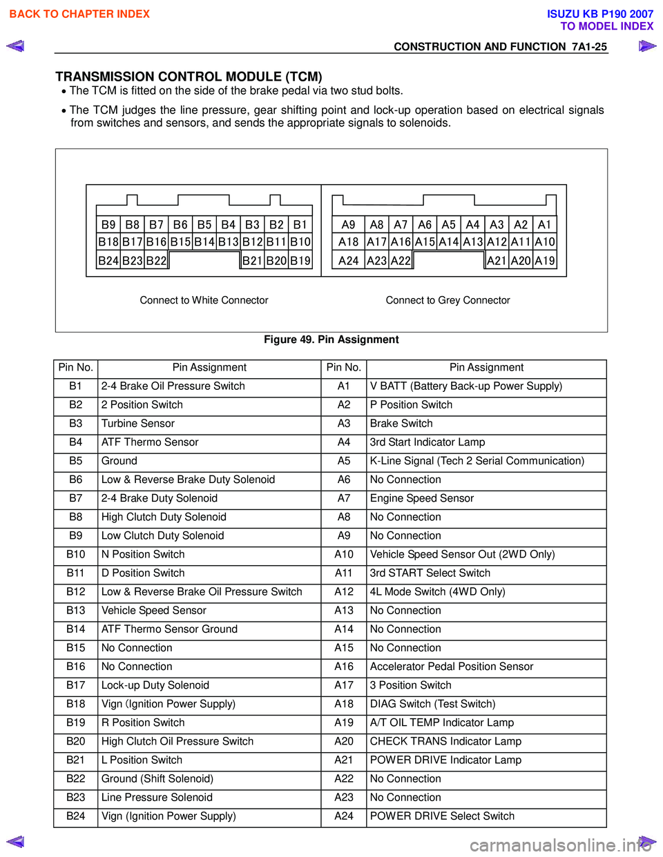
TRANSMISSION CONTROL MODULE (TCM)
• The TCM is fitted on the side of the brake pedal via two stud bolts.
• The TCM judges the line pressure, gear shifting point and lock-up operation based on electrical signals
from switches and sensors, and sends the appropriate signals to solenoids.
B9 B8 B7 B6 B5 B4 B3 B2 B1 A9 A8 A7 A6 A5 A4 A3 A2 A1
B18 B17 B16 B15 B14 B13 B12 B11 B10 A18 A17 A16 A15 A14 A13 A12 A11 A10
B24 B23 B22 B21 B20 B19 A24 A23 A22 A21 A20 A19
Connect to White Connector Connect to Grey Connector
Figure 49. Pin Assignment
Pin No. Pin Assignment Pin No.Pin Assignment
B1 2-4 Brake Oil Pressure Switch A1 V BATT (Battery Back-up Power Supply)
B2 2 Position Switch A2 P Position Switch
B3 Turbine Sensor A3 Brake Switch
B4 ATF Thermo Sensor A4 3rd Start Indicator Lamp
B5 Ground A5 K-Line Signal (Tech 2 Serial Communication)
B6 Low & Reverse Brake Duty Solenoid A6 No Connection
B7 2-4 Brake Duty Solenoid A7 Engine Speed Sensor
B8 High Clutch Duty Solenoid A8 No Connection
B9 Low Clutch Duty Solenoid A9 No Connection
B10 N Position Switch A10 Vehicle Speed Sensor Out (2W D Only)
B11 D Position Switch A11 3rd START Select Switch
B12 Low & Reverse Brake Oil Pressure Switch A12 4L Mode Switch (4W D Only)
B13 Vehicle Speed Sensor A13 No Connection
B14 ATF Thermo Sensor Ground A14 No Connection
B15 No Connection A15 No Connection
B16 No Connection A16 Accelerator Pedal Position Sensor
B17 Lock-up Duty Solenoid A17 3 Position Switch
B18 Vign (Ignition Power Supply) A18 DIAG Switch (Test Switch)
B19 R Position Switch A19 A/T OIL TEMP Indicator Lamp
B20 High Clutch Oil Pressure Switch A20 CHECK TRANS Indicator Lamp
B21 L Position Switch A21 POW ER DRIVE Indicator Lamp
B22 Ground (Shift Solenoid) A22 No Connection
B23 Line Pressure Solenoid A23 No Connection
B24 Vign (Ignition Power Supply) A24 POW ER DRIVE Select Switch
BACK TO CHAPTER INDEX
TO MODEL INDEX
ISUZU KB P190 2007
Page 4267 of 6020
7A1-28 CONSTRUCTION AND FUNCTION
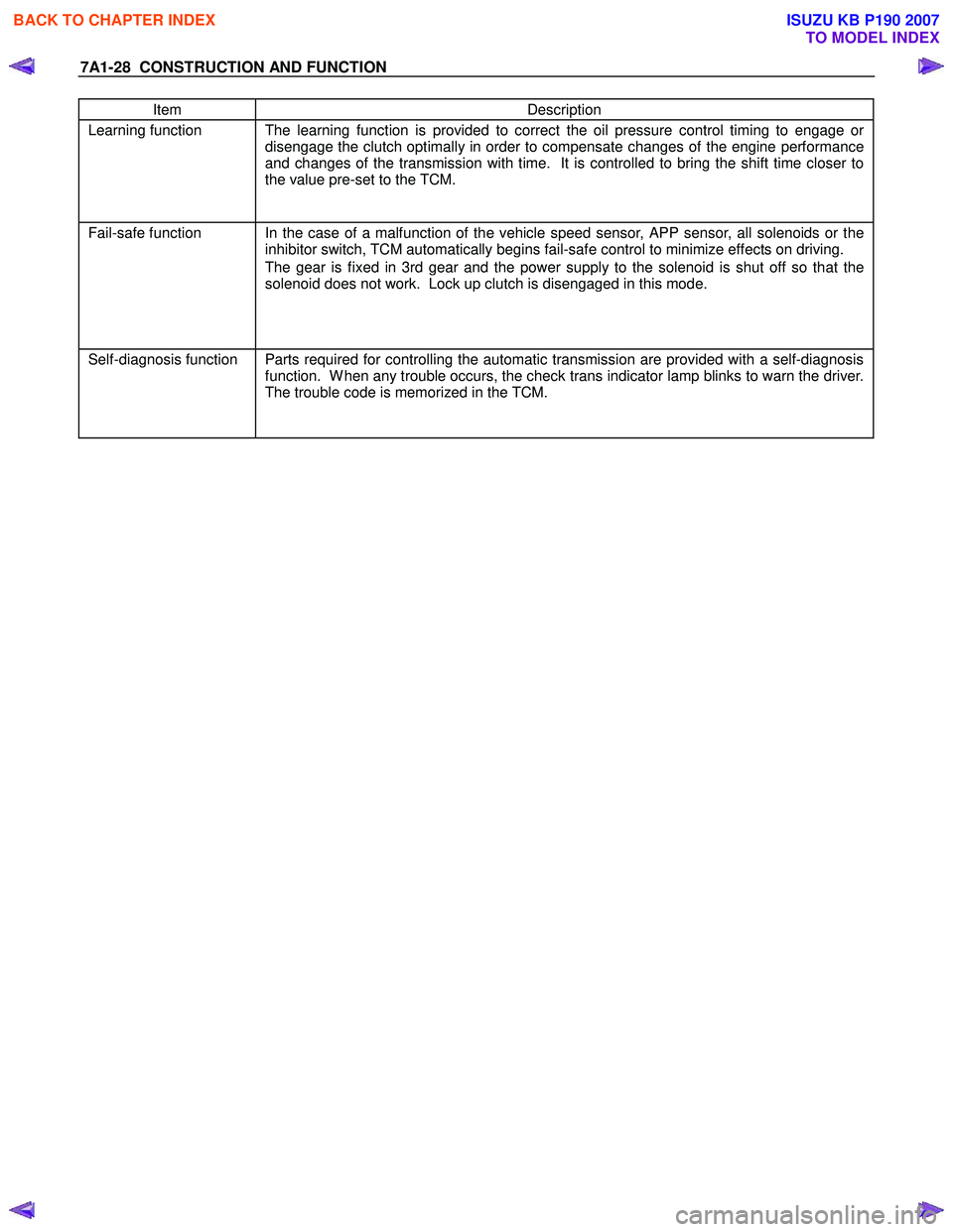
Item Description
Learning function The learning function is provided to correct the oil pressure control timing to engage or
disengage the clutch optimally in order to compensate changes of the engine performance
and changes of the transmission with time. It is controlled to bring the shift time closer to
the value pre-set to the TCM.
Fail-safe function In the case of a malfunction of the vehicle speed sensor, APP sensor, all solenoids or the
inhibitor switch, TCM automatically begins fail-safe control to minimize effects on driving.
The gear is fixed in 3rd gear and the power supply to the solenoid is shut off so that the
solenoid does not work. Lock up clutch is disengaged in this mode.
Self-diagnosis function Parts required for controlling the automatic transmission are provided with a self-diagnosis
function. W hen any trouble occurs, the check trans indicator lamp blinks to warn the driver.
The trouble code is memorized in the TCM.
BACK TO CHAPTER INDEX
TO MODEL INDEX
ISUZU KB P190 2007
Page 4268 of 6020

CONSTRUCTION AND FUNCTION 7A1-29
CONTROL ITEM, INPUT AND OUTPUT
Control item
Item
Line
pressure control
Gear shift
control
Shift
pattern
selection
Lock-up control Direct
electronic shift
control
(DECS)
Learning control
Fail-safe function
Self-
diagnosis function
Speed sensor
Turbine sensor
Engine speed sensor
Brake switch
Inhibitor switch
Mode select switch
4L switch (4W D Only)
ATF thermo sensor
High clutch oil pressure switch
2-4 brake oil pressure switch
Low & Reverse brake oil pressure
switch
Input
Accelerator Pedal position sensor
Line pressure solenoid
Low clutch solenoid
High clutch solenoid
2-4 brake solenoid
Low & Reverse brake solenoid
Lock-up solenoid
Shift pattern indicator lamp
ATF temperature indicator lamp
Output
Check trans indicator lamp
BACK TO CHAPTER INDEX
TO MODEL INDEX
ISUZU KB P190 2007
Page 4273 of 6020
7A1-34 CONSTRUCTION AND FUNCTION
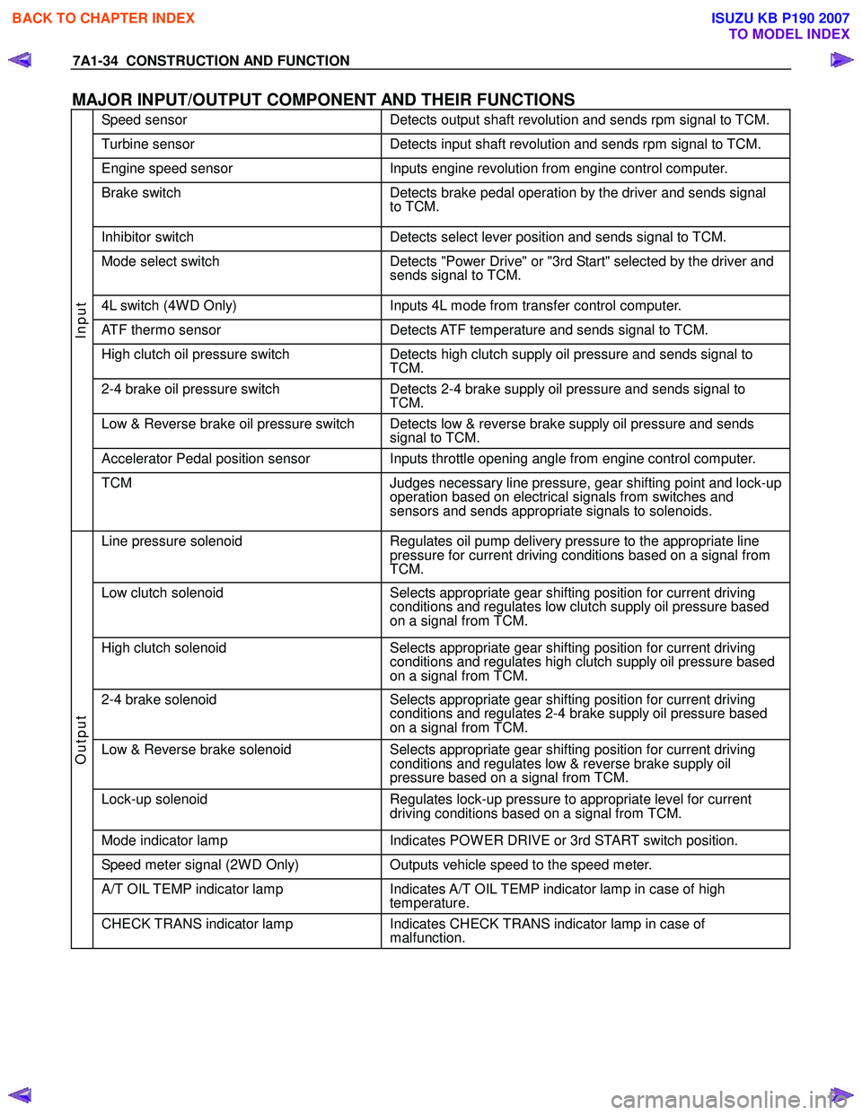
MAJOR INPUT/OUTPUT COMPONENT AND THEIR FUNCTIONS
Speed sensor Detects output shaft revolution and sends rpm signal to TCM.
Turbine sensor Detects input shaft revolution and sends rpm signal to TCM.
Engine speed sensor Inputs engine revolution from engine control computer.
Brake switch Detects brake pedal operation by the driver and sends signal
to TCM.
Inhibitor switch Detects select lever position and sends signal to TCM.
Mode select switch Detects "Power Drive" or "3rd Start" selected by the driver and
sends signal to TCM.
4L switch (4W D Only) Inputs 4L mode from transfer control computer.
ATF thermo sensor Detects ATF temperature and sends signal to TCM.
High clutch oil pressure switch Detects high clutch supply oil pressure and sends signal to
TCM.
2-4 brake oil pressure switch Detects 2-4 brake supply oil pressure and sends signal to
TCM.
Low & Reverse brake oil pressure switch Detects low & reverse brake supply oil pressure and sends signal to TCM.
Accelerator Pedal position sensor Inputs throttle opening angle from engine control computer.
Input
TCM Judges necessary line pressure, gear shifting point and lock-up
operation based on electrical signals from switches and
sensors and sends appropriate signals to solenoids.
Line pressure solenoid Regulates oil pump delivery pressure to the appropriate line
pressure for current driving conditions based on a signal from
TCM.
Low clutch solenoid Selects appropriate gear shifting position for current driving
conditions and regulates low clutch supply oil pressure based
on a signal from TCM.
High clutch solenoid Selects appropriate gear shifting position for current driving
conditions and regulates high clutch supply oil pressure based
on a signal from TCM.
2-4 brake solenoid Selects appropriate gear shifting position for current driving
conditions and regulates 2-4 brake supply oil pressure based
on a signal from TCM.
Low & Reverse brake solenoid Selects appropriate gear shifting position for current driving
conditions and regulates low & reverse brake supply oil
pressure based on a signal from TCM.
Lock-up solenoid Regulates lock-up pressure to appropriate level for current
driving conditions based on a signal from TCM.
Mode indicator lamp Indicates POW ER DRIVE or 3rd START switch position.
Speed meter signal (2W D Only) Outputs vehicle speed to the speed meter.
A/T OIL TEMP indicator lamp Indicates A/T OIL TEMP indicator lamp in case of high
temperature.
Output
CHECK TRANS indicator lamp Indicates CHECK TRANS indicator lamp in case of
malfunction.
BACK TO CHAPTER INDEX
TO MODEL INDEX
ISUZU KB P190 2007
Page 4274 of 6020
CONSTRUCTION AND FUNCTION 7A1-35
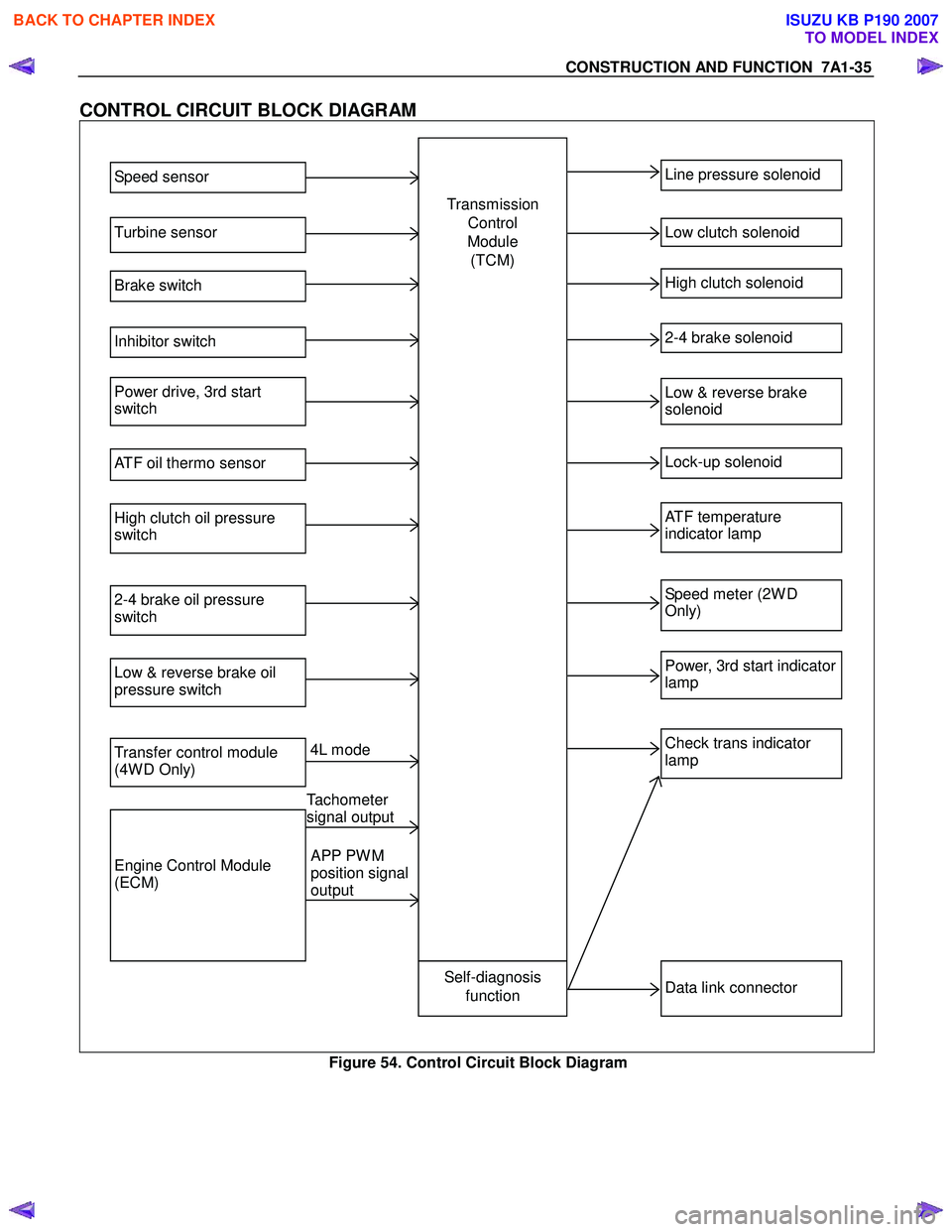
CONTROL CIRCUIT BLOCK DIAGRAM
Speed sensor
Turbine sensor
Brake switch
Inhibitor switch
Power drive, 3rd start
switch
ATF oil thermo sensor
High clutch oil pressure
switch
2-4 brake oil pressure
switch
Low & reverse brake oil
pressure switch
Transfer control module
(4W D Only)
Engine Control Module
(ECM)
Line pressure solenoid
Low clutch solenoid
High clutch solenoid
2-4 brake solenoid
Low & reverse brake
solenoid
Lock-up solenoid
ATF temperature
indicator lamp
Speed meter (2W D
Only)
Power, 3rd start indicator
lamp
Check trans indicator
lamp
Data link connector Self-diagnosis
function
Transmission
Control
Module (TCM)
4L mode
Tachometer
signal output
APP PW M
position signal
output
Figure 54. Control Circuit Block Diagram
BACK TO CHAPTER INDEX
TO MODEL INDEX
ISUZU KB P190 2007
Page 4301 of 6020
TRANSMISSION CONTROL SYSTEM (JR405E) 7A2-17
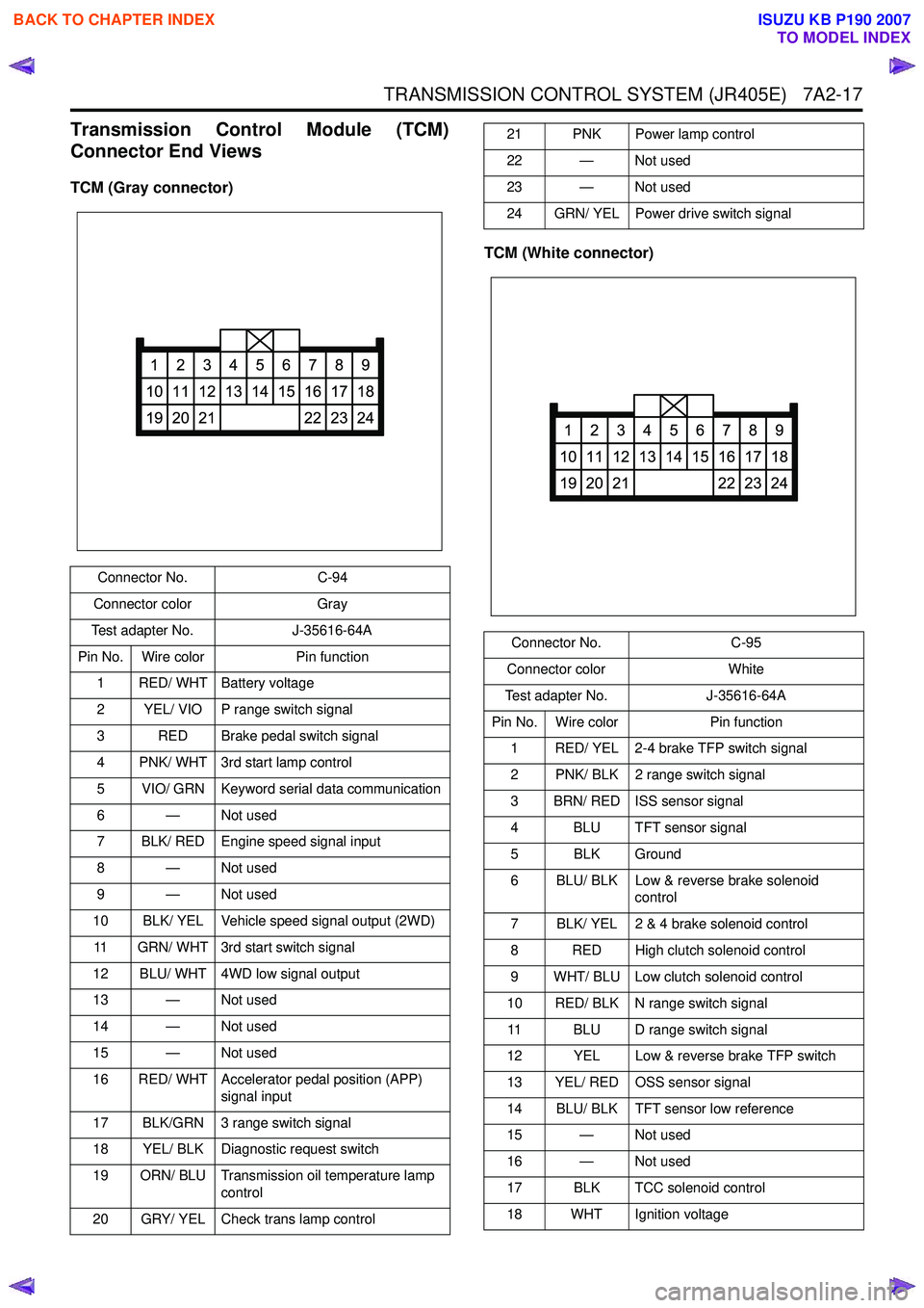
Transmission Control Module (TCM)
Connector End Views
TCM (Gray connector)
TCM (White connector)
Connector No.C-94
Connector color Gray
Test adapter No. J-35616-64A
Pin No. Wire color Pin function
1 RED/ WHT Battery voltage
2 YEL/ VIO P range switch signal
3 RED Brake pedal switch signal
4 PNK/ WHT 3rd start lamp control
5 VIO/ GRN Keyword serial data communication
6 — Not used
7 BLK/ RED Engine speed signal input
8 — Not used
9 — Not used
10 BLK/ YEL Vehicle speed signal output (2WD)
11 GRN/ WHT 3rd start switch signal
12 BLU/ WHT 4WD low signal output
13 — Not used
14 — Not used
15 — Not used
16 RED/ WHT Accelerator pedal position (APP) signal input
17 BLK/GRN 3 range switch signal
18 YEL/ BLK Diagnostic request switch
19 ORN/ BLU Transmission oil temperature lamp control
20 GRY/ YEL Check trans lamp control
1
10
19
2
11
20
3
12
21
4
13
5
14
6
15
7
16
22
8
17
23
9
18
24
21 PNK Power lamp control
22 — Not used
23 — Not used
24 GRN/ YEL Power drive switch signal
Connector No. C-95
Connector color White
Test adapter No. J-35616-64A
Pin No. Wire color Pin function
1 RED/ YEL 2-4 brake TFP switch signal
2 PNK/ BLK 2 range switch signal
3 BRN/ RED ISS sensor signal
4 BLU TFT sensor signal
5 BLK Ground
6 BLU/ BLK Low & reverse brake solenoid control
7 BLK/ YEL 2 & 4 brake solenoid control
8 RED High clutch solenoid control
9 WHT/ BLU Low clutch solenoid control
10 RED/ BLK N range switch signal 11 BLU D range switch signal
12 YEL Low & reverse brake TFP switch
13 YEL/ RED OSS sensor signal
14 BLU/ BLK TFT sensor low reference
15 — Not used
16 — Not used
17 BLK TCC solenoid control
18 WHT Ignition voltage
1
10
19
2
11
20
3
12
21
4
13
5
14
6
15
7
16
22
8
17
23
9
18
24
BACK TO CHAPTER INDEX
TO MODEL INDEX
ISUZU KB P190 2007
Page 4305 of 6020
TRANSMISSION CONTROL SYSTEM (JR405E) 7A2-21
Diagnostic Information and Procedures
Diagnostic Starting Point - Transmission Controls
Begin the system diagnosis with Diagnostic System
Check - Transmission Controls. The Diagnostic System
Check - Transmission Controls will provide the
following information:
• The identification of the control modules which command the system.
• The ability of the control modules to communicate through the serial data circuit.
• The identification of any stored diagnostic trouble codes (DTCs) and the their statuses.
The use of the Diagnostic System Check -
Transmission Controls will identify the correct
procedure for diagnosing the system and where the
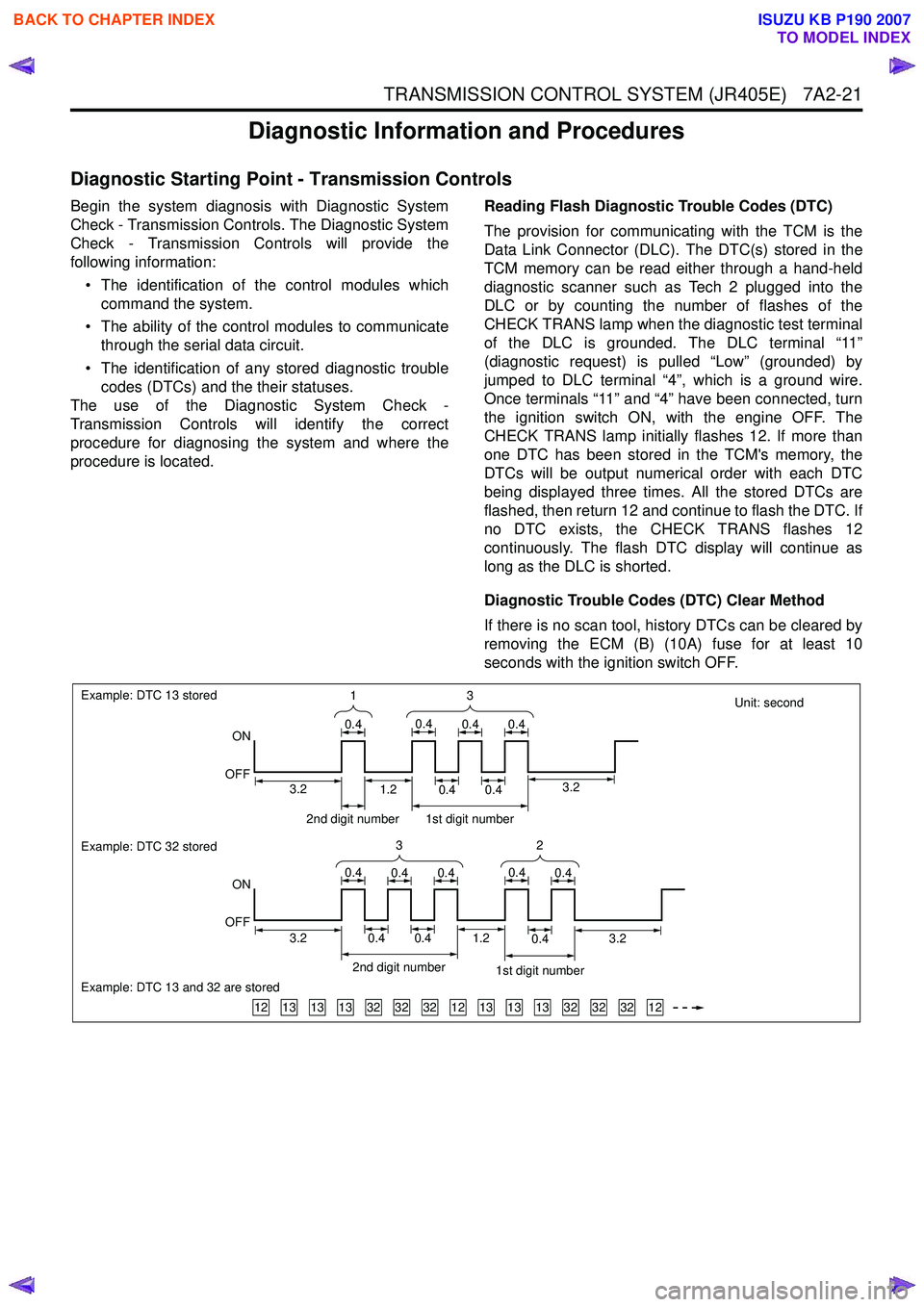
procedure is located. Reading Flash Diagnostic Trouble Codes (DTC)
The provision for communicating with the TCM is the
Data Link Connector (DLC). The DTC(s) stored in the
TCM memory can be read either through a hand-held
diagnostic scanner such as Tech 2 plugged into the
DLC or by counting the number of flashes of the
CHECK TRANS lamp when the diagnostic test terminal
of the DLC is grounded. The DLC terminal “11”
(diagnostic request) is pulled “Low” (grounded) by
jumped to DLC terminal “4”, which is a ground wire.
Once terminals “11” and “4” have been connected, turn
the ignition switch ON, with the engine OFF. The
CHECK TRANS lamp initially flashes 12. If more than
one DTC has been stored in the TCM's memory, the
DTCs will be output numerical order with each DTC
being displayed three times. All the stored DTCs are
flashed, then return 12 and continue to flash the DTC. If
no DTC exists, the CHECK TRANS flashes 12
continuously. The flash DTC display will continue as
long as the DLC is shorted.
Diagnostic Trouble Codes (DTC) Clear Method
If there is no scan tool, history DTCs can be cleared by
removing the ECM (B) (10A) fuse for at least 10
seconds with the ignition switch OFF.
Unit: second
131313323232121313133232321212
Example: DTC 13 stored
ON
OFF
Example: DTC 32 stored
Example: DTC 13 and 32 are stored
ON
OFF 3
1
0.40.40.40.4
32
0.40.40.40.40.4
2nd digit number1st digit number
3.23.20.40.40.41.2
2nd digit number 1st digit number
0.40.41.23.23.2
BACK TO CHAPTER INDEX
TO MODEL INDEX
ISUZU KB P190 2007